
Abstract
A coupled finite volume-element method is developed to simulate the transient thermal deformation of water-cooled mirror by considering fluid flow and convective heat transfer. The simulation process consists of two steps: the 3D finite volume models of fluid flow and heat transfer equation are solved to obtain the time-dependent temperature field by using CFD; then, the obtained temperature field used as final temperature field is unidirectionally coupled to the finite element model for solving the thermoplastic equation. It is concluded that fluid flow not only affects the magnitude of temperature rise and thermal deformation, but also affects the distribution of temperature and thermal deformation. The temperature gradient in the thickness direction (z direction) is found to be much larger than that in transverse direction. It is found that the temperature and the consequent deformation of water-cooled mirror increase significantly in the first seconds and gradually become steady state in the subsequent time. Experiments are conducted to estimate the precision of numerical models, and the experimental results agree well with the simulated results.
1. Introduction
The thermally induced deformation of mirror surface restricts the development of high-energy laser (HEL) systems, especially with the increase of laser power and working time. Water-cooled mirror, employing heat sinks with mini/microchannels or micropores for cooling, is an effective way to limit the thermal distortion of mirror surface [1, 2]. However, the thermal deformation characteristic of water-cooled mirror is closely related to the geometric dimension, channel shape, configuration, inlet/outlet arrangement, and material [3]. It is quite laborious and expensive to conduct the designing, production, and testing of such water-cooled mirrors, partially due to the extensive analysis required to predict their deformation performance for various beam loadings and coolant flow rates [4]. Therefore, numerical simulation plays an important role in the estimation of deformation performance of water-cooled mirror.
For pursuing accurate modeling of the water-cooled mirror, the problem should be divided into two major tasks [5]. The first task is to obtain accurate temperature field expression, which completely characterizes thermal diffusion and convective heat transfer behavior for arbitrary spatial and temporal loading of boundary, convective term, and initial conditions. The second task is to analyze the thermoelastic response of mirror surface to the temperature field. Therefore, in order to acquire accurate thermal deformation of the water-cooled mirror, the accurate temperature field needs to be computed first.
Initially, for acquiring the temperature field, the average heat transfer coefficient calculated from empirical formulas was employed to solve the heat conduction equation [6–8]. Later, to achieve a higher precision, the analytical solution for the temperature distribution of mirrors was obtained by using integral transform technique [9], Green's functions [10, 11], finite difference method [12], and finite element method [13]. In the previous studies, the fluid flow and conjugated heat transfer process on the interface were assumed to be homogeneous process for simplifying the calculation. Based on these assumptions, finite element method (FEM) is widely used to solve the thermoelastic equation for analyzing the thermal deformation of mirror surface. In these studies, the influence of channel dimension [14, 15], shape and configuration of the flow channels [16, 17], properties of materials, and the intensity of the laser radiation [18, 19] were investigated. However, the assumption may lead to great discrepancy between the predictions and the facts, since the heat transfer performance shows different properties along the flow directions, especially when the flow passage and the hydraulic diameter are short [20, 21]. Besides, the local heat input and heat transfer coefficient of each flow channel is not uniform for different arrangements of inlet/outlet and flow field configurations [22, 23]. Therefore, these modeling studies may not be able to accurately exhibit the influence of nonuniform cooling on the temperature distribution of mirror surface and the consequent thermal deformation.
In fact, the temperature prediction involving heat conduction and forced convection is extensively conducted to investigate the cooling performance of microchannel heat sink via computational fluid dynamics (CFD). Researchers have carried out lots of numerical simulations of forced single phase water flowing in heat sinks with different physical dimensions, concluding that the predicted results agree well with the experimental data [24–26]. In the mentioned numerical simulations, finite volume method (FVM) is widely used to solve the conjugate heat transfer problem for simultaneously predicting of the temperature fields in the solid and liquid regions. Consequently, it is reasonable to acquire precision temperature field of the mirror body by means of FVM. Hu et al. [27] numerically analyzed the deformation of water-cooled mirror by coupling the FVM-solved temperature to the finite element model. However, only the wall temperatures were coupled to the finite element model as a thermal boundary condition in the study. It means that the heat conduction equation needs to be solved again for obtaining the global structural temperature, which will induce extra calculation and consequent error.
Based on the above information, an alternate method of modeling a water-cooled mirror's thermal distortion is proposed, taking flow passage configurations and fluid flow heat transfer into account for pursuing higher precision, that is, using FVM to solve the three-dimensional (3D) CFD model of water-cooled mirror for obtaining the temperature field. Then, the obtained temperature field of mirror body is coupled unidirectionally to the finite element model of the thermoplastic equation as a final temperature field, without solving the heat conduction equation again. In this study, the transient heat transfer and thermal deformation characteristics of water-cooled laser mirror under high intensity laser irradiation are investigated by using the developed finite volume-finite element method. The numerical model is examined with different working conditions, including different laser power and with/without water cooling. Besides, experiments are conducted to verify the numerical results by examining peak-valley (Δd) and root mean square (RMS) value of thermal deformation of mirror surface.
2. Description of Numerical Simulation
2.1. Physical Model
Figure 1 shows the schematic of the water-cooled mirror chosen for the present study. It consists of three components: mirror layer, chamber layer, and sealed cap. The size of the mirror layer is fixed at L m = 80 mm, W m = 76 mm, and H m = 6 mm. There are twenty channels with width of a = 1.3 mm and depth of b = 3 mm in the mirror layer. The interval of channels is limited to c = 2 mm. The size of chamber layer is fixed at D c = 118 mm and H c = 8 mm. There are four through holes with the same dimensions in the chamber layer. The sealed cap has two pairs of inlets and outlets with the same diameter of 10 mm. The arrangement of inlets and outlets is indicated by the arrows, leading to two independent fluid regions with opposite flow direction. The faces of Fix-A1~Fix-A4 are fixed in the z-direction for mechanical constraint. The mirror is made of silicon and the coolant is water.

Consititution and assembling of the water-cooled laser mirror.
2.2. Numerical Simulation of Fluid Flow and Heat Transfer
The mirror was used as a reflector in an optical transmission system. In practical applications, an annular laser beam with inner diameter of Dr1 = 20 mm and outer diameter of Dr2 = 40 mm radiates on the mirror surface, as shown in Figure 2. The center of the laser beam overlaps with the center of mirror surface. The annular laser beam with a wavelength of 3.8 μm is produced by an unstable optical resonator of a continuous wave chemical laser. The laser intensity that distributes in annulus is defined by [6]

where the intensity spatial gradient γ gives the degree of nonuniformity of laser intensity across the beam along the x direction (x can be substituted by y in different actual situation). P is the incident laser power.
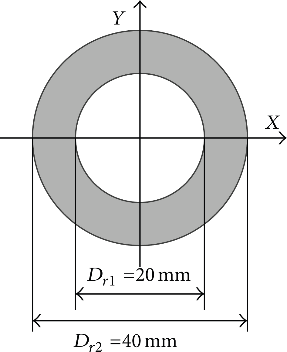
Diagram of laser beam section.
The thermal input caused by laser-induced heat is considered as absorbed heat flux q a , which is given by [28]
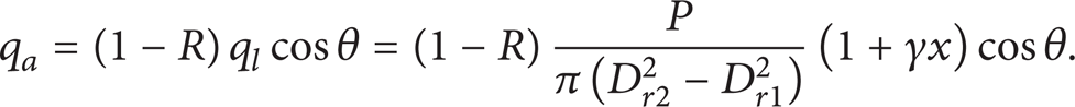
In which, R is reflectivity, fixing at 99%; θ is the laser incidence angle and is fixed at 15°. γ = 0 is used here, since the laser intensity distribution is assumed to be uniform in the annulus.
Considering flow velocity could be different in each channel, the overall averaged Reynolds number is considered as an indication of the flow through the channel layer. It is defined as [26]

where ρ f and μ are the density and kinematic viscosity of water, respectively. The value of hydraulic diameter, D h , is determined by [26]

The average velocity of the coolant in the channels, vavg, is defined by
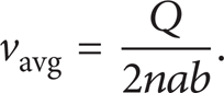
In which, Q is the total flow rate, and n = 10 is the number of channels between each pair of inlet and outlet. The value Reavg is calculated to be 2290 via substituting (2) and (3) into (1). Hence, the hypothesis of laminar is suitable for this simulation.
To focus on the fluid flow and heat transfer, several assumptions are made: The flow is laminar; fluid is in single phase and incompressible; the outer face of mirror is adiabatic; the properties of water are temperature independent. Besides, properties of silicon are assumed to be isotropic and linearly changed with temperature between 250 K and 400 K [29, 30]. All the properties of materials are listed in Table 1.
Physical properties of material.

Under the stated analysis and assumptions, the governing equations for the fluid and solid including continuity, momentum, and energy equations are expressed as follows:

where
The boundary conditions for these equations are related to the operating conditions and given as follows.
A uniform velocity is applied at the inlet
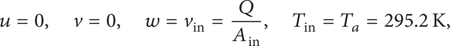
at outlet

No-slip boundary conditions are imposed on the interface

on the laser irradiation area

In (7a), (7b), (7c), and (7d), vin, Ain, T a , and pout are inlet velocity, cross-sectional area of entrance, ambient temperature, and pressure at the outlet, respectively. n is the direction normal to the inlet/outlet plane.
FLUENT is employed to solve the governing equations. The convective and conductive terms were discretized using second-order upwind and second-order central-difference schemes, respectively. The SIMPLE method was applied to handle the coupling of the pressure field and velocity field. Grids near the boundary wall and interface are set as denser to achieve accurate results. A mesh sensitivity check is conducted by analyzing the largest temperature rise of models with different mesh density. At last, a computational domain with 1 × 10⁷ grids of liquid part and 0.9 × 10⁷ grids of solid is employed throughout the computation in this study. The convergence absolute criteria of continuity, velocity, and energy are set to be 1 × 10⁻⁴, 1 × 10⁻⁶, and 1 × 10⁻⁸ respectively. The results of transient temperature distribution are saved every one-fifth of a second, which will be utilized for final temperature and coupled to mirror body for deformation analysis.
2.3. Numerical Simulations of the Thermal Deformation
The surface distortion caused by the pressure of fluid flow is ignored in the simulation. Besides, the total thermal deformation is less than 2 μm, which means structural deformation has little impact on fluid flow. Therefore, the transient temperatures obtained from the finite volume model are unidirectionally coupled to the mirror body of finite element model as a final temperature field, for analyzing transient thermal deformation of the mirror. The coupling process uses the node joint and the intermediate interpolation, which are accomplished on the software ANSYS WORKBENCH. The initial temperature of the mirror body is equal to the ambient temperature. Computational domains of mirror body with 1.57 × 10⁶, 2.14 × 10⁶, and 4.20 × 10⁶ grids are used to test the grid dependence of solution. At last, the computational part with 2.14 × 10⁶ grids is employed throughout the computation of the finite element model of the mirror body, since it is seen that almost identical results of thermal deformation are predicted when 2.14 × 10⁶ and 4.20 × 10⁶ grids are used.
In order to estimate the thermal stress distribution in each time interval, it is assumed that the mirror reaches thermal equilibrium at the end of each interval time. The governing thermal stress equations in three directions (x, y, and z) are shown as follows [31].
Equilibrium equations are


Geometry equations are

Physics equations are


where u, v, ω, ε x , ε y , ε z , σ x , σ y , and σ z are displacement, normal strain, and normal stress in x, y, and z direction, respectively. τ xy , τ yz , τ xz , γ xy , γ yz , and γ xz are shear strain and shear stress in xy, yz, and xz plane, respectively. ε, υ, E, and ΔT, respectively, present volume strain, Poisson's ratio, Young's modulus, and temperature rise. G is the shear modulus, expressed as G = E/2(1 + ν).
3. Analysis and Discuss
Three sets of model parameters utilized in this study are listed in Table 2. The flow rates of models 1 and 3 are fixed at 50 mL/s, for eliminating the ill effects of vibration and additional pressure.
Parameters utilized in the simulation and experiments.

3.1. Temperature Distribution
The temperature distributions of mirror surface versus laser irradiating time are presented in Figure 3. It can be observed that the surface temperature of model 2 increases dramatically from the beginning to the end (0–5 s), and the maximum temperature rise is up to 51 K (Figure 3(b)). The surface temperatures of models 1 and 3 also increase rapidly in the first seconds (0–1 s) but become steady in subsequent time (2–5 s), as shown in Figures 3(a)/3(c). Besides, the temperature rises of models 1 and 3 reach 32 K and 24 K, respectively, which are much lower than that of model 2. This is due to the heat dissipation induced by water flow in channels.
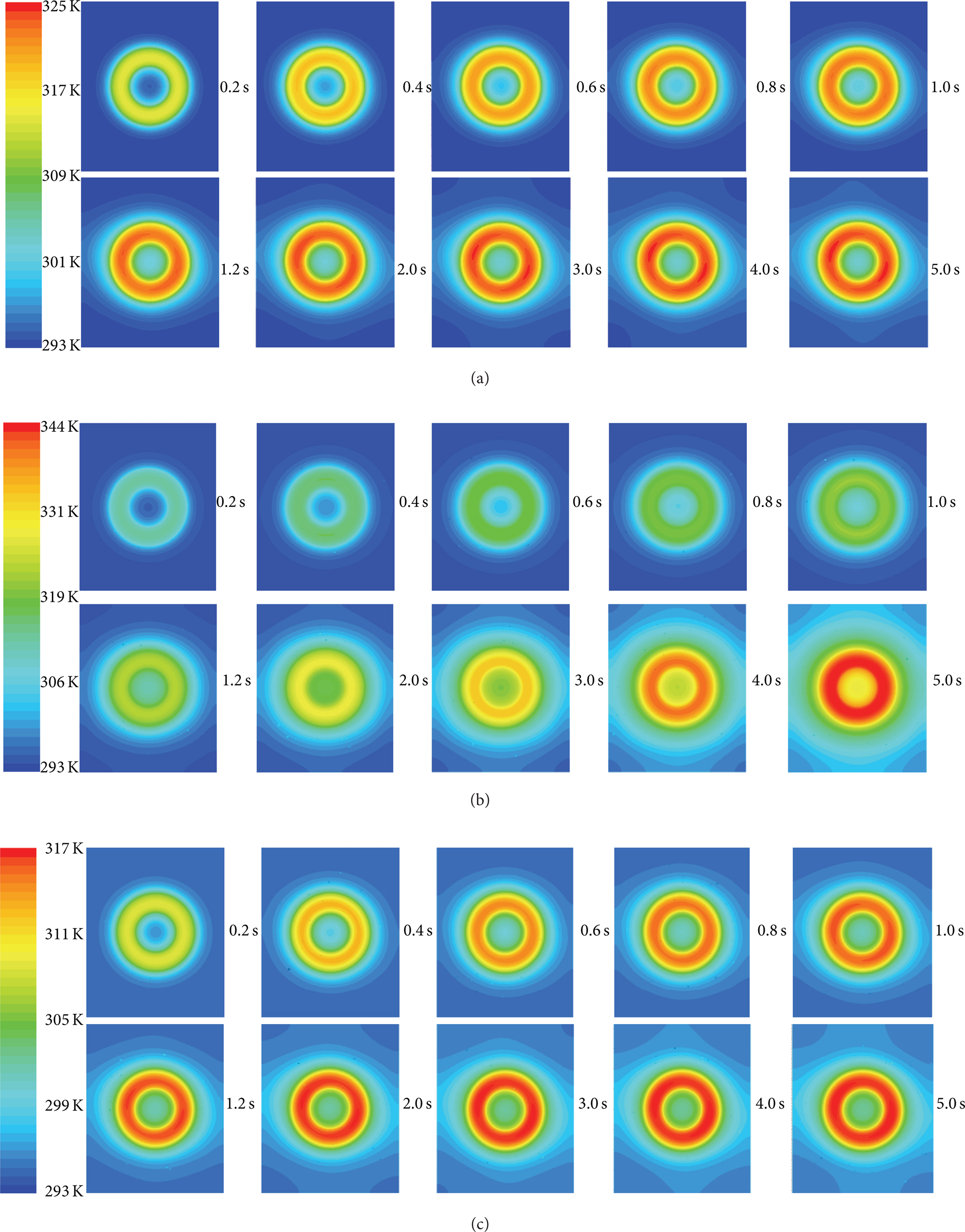
Transient temperature distribution of mirror surface: (a) model 1; (b) model 2; and (c) model 3.
In addition, a centrosymmetric pattern of temperature distribution can be found in model 2, while asymmetric patterns are presented in models 1 and 3. A more obvious difference can be seen in Figures 4(a) and 4(b), which present the surface temperature contours of model 1 and model 2 at 5 s, respectively. This phenomenon illustrates that fluid flow impacts both temperature rise and temperature distribution. Both of the two highest isotherms look like crescent moons, which are located at the downstream zone according to flow direction, as shown in Figure 4(a). First, this is because there are two independent cooling regions conducted by flowing fluid with opposite flow direction. Second, the heat transfer coefficient decreases along the flow directions [24, 25]. Hence, loading a constant heat transfer coefficient to simplify the process of convection heat transfer may induce inaccuracy of the temperature distribution.

Temperature contour of mirror surface of model 1 (a) and model 2 (b) at 5 s; (c) velocity magnitude contours in model 1.
Figure 4(c) exhibits the velocity contour of water in channels, in which the largest velocity locates in upstream region and the second highest value locates in downstream region. This is caused by swirling motion of the fluid as it flows from buffer zone to channels. The swirling motion leads to local high speed and thin boundary layer, which enhance the local heat transfer coefficient. Furthermore, stagnation regions can be found in the buffer zone. Since it is not situated in the direct thermal path, the stagnation regions have little influence on heat performance.
From the above, mirrors with water-cooling channels show a different thermal behavior, compared to the mirror without cooling. Besides, fluid flow and uneven distributed heat transfer coefficient also play an important role in the formation of the temperature field. For optimizing the channel configuration of water-cooled mirror, it is suggested that the swirling motion regions should be placed under the irradiated zone and near the center area, while stagnation regions should be located near radiation-free zone.
3.2. Thermal Induced Deformation of Mirror Surface and Cross-Section
The main cause for the mirror surface deformation and the consequent beam quality degradation is a bending of the whole mirror caused by local expansion near the surface regions. This leads to both a higher expansion at the place of the laser irradiation area and adjacent regions. The peak-valley value of thermal deformation (Δd) in this study is defined as

where dmax and d min are the maximum and minimum of thermal deformation of mirror surface in z-direction, respectively.
The Δd distribution contours of models 1 and 2 are presented in Figure 5, corresponding to temperature distribution of Figures 4(a) and 4(b), respectively. The maximum Δd of models 1 and 2 are 0.91 μm and 1.35 μm, respectively. It can be found that the maximum Δd of model 1 is much smaller than that of model 2. Besides, two crescent-shaped isotherms in Figure 5(a) can be found in respective downstream regions, which show similar patterns as temperature distribution in Figure 4(a).

Deformation contour of mirror surface of model 1 (a) and model 2 (b) at 5 s.
The temperature distributions of the cross-section (y = 0) and the corresponding Δd distributions are presented in Figure 6. It shows that higher local temperature results in higher local deformation, since the deformation distribution in z-direction exhibits the similar pattern as temperature distribution in z-direction, as shown in Figure 6(a). Besides, the temperature gradient in z-direction can be found to be higher than that in x-direction. The same phenomenon of deformation gradient can be found in Figure 6(b), indicating that the thickness of mirror layer impact directly on thermal deformation. Based on the analysis, it can be found that optimizing the temperature distribution in z-direction or the thickness distribution of mirror layer may be an effective way to reduce the thermal deformation of mirror surface. For instance, designing a concave in the rear surface of mirror layer, ensuring the high temperature locates in the thin region and the low temperature locates in the thick region, may help to limit the thermal deformation.

Temperature distribution of (a) and thermal deformation (Δd) (b) of the cross-section (y = 0) in model 1.
3.3. Transient Thermal Deformation and Experimental Verification
Wavefront error is commonly quantified by the peak-to-valley error (Δd) and the RMS error [32]. The predicted time-dependent Δd and RMS thermal deformation of mirror surface are plotted in Figure 7. For models 1 and 3 (water-cooled mirror), the initial Δd is sensitive to the irradiation time and laser power, as it increases dramatically in the first seconds and becomes in stable state in subsequent time. This phenomenon is in line with the above description of Figures 3 and 6. For model 2 (without cooling), growth rate of Δd has been maintained at a higher level all over the working time, which causes the Δd of model 2 to be much larger than that of models 1 and 3. The difference between models 1 and 2 is ascribed to efficient heat dissipation induced by water cooling. Besides, a higher absorbed heat flux (incidence laser power) results in a larger thermal deformation, which can be found from the curves of models 1 and 3. The similar tendency can be seen in RMS, compared to Figures 7(a) and 7(b).

Transient numerical and experimental results of mirror surface, (a) maximum Δd and (b) RMS of thermal deformation.
Figure 8(a) shows the experimental facility in the present investigation, including the fluidic path and the light path. The laser beam irradiates on the mirror surface in a small incident angle (θ = 15°), and the deformation of the mirror surface is real-time detected by the interferometer (PhaseCam 4010). By adjusting the flow rate to 50 mL/s, the deformation caused by vibration and the additional pressure of water flow can be ignored. The measured intensity distribution of annular laser beam used here is presented in Figure 8(b), which is assumed to be uniformly distributed.

(a) Schematic of experimental apparatus and (b) laser beam intensity distribution.
Corresponding to the conditions listed in Table 2, experiments are conducted to validate the computational procedures and numerical method for the current study. The mean average error (MAE) between experimental data and numerical predictions is defined as

where Φ exp and Φnum are experimental and numerical value at each test time, respectively. M = 14 is the number of test point in each model.
The experimental results of Δd and RMS are plotted in Figure 7. MAE (Δd) of models 1 and 3 are calculated to be 6.9% and 9.9%, respectively. MAE (RMS) of models 1 and 3 are calculated to be 10% and 7.1%, respectively. It is obvious that the numerical results agree well with the experimental results, in spite of the fact that the numerical results are found to be a little bit larger than the experimental data. This may be caused by the conservative hypothesis of laminar flow and neglecting of surface roughness of the channels in a laser mirror, which affects the thermal performance of convection a lot [33]. The good agreement confirms that the simulation method used in this study is valid to model the conduction, convection, and deformation of water-cooled laser mirror, which also can be used to estimate the heat and deformation performance of water-cooled mirror with different structure.
In addition, it is clear that water cooling is really helpful in limiting the thermal deformation, since Δd is reduced from 1.2 μm to 0.86 μm under the condition of q a = 74 × 104 W/m2, as shown in Figure 7(a). However, the deformation is still too large relative to the incident laser wavelength. Therefore, new structure of water-cooled mirror with more effective heat and deformation performance need to be designed and need to ensure that it satisfies the high power working condition.
4. Conclusions
In this paper, a coupled finite volume-finite element method is used to simulate the transient thermal deformation of water-cooled mirror by considering the fluid flow and convective heat transfer. The simulation process consists of two steps: the 3D finite volume models of fluid flow and heat transfer equation are solved to obtain the time-dependent temperature field by using FVM; then, the temperature field is used as final temperature field and unidirectionally coupled to the finite element model for solving the thermoplastic equation. Experiments are conducted to estimate the precision numerical models, and the experimental results agree well with the simulated results.
The numerical results show that temperature and the consequent deformation of water-cooled mirror increase significantly in the first seconds and gradually turn to steady state in the subsequent time. Under the irradiation region, the temperature gradient in the thickness direction (z-direction) is found to be much larger than that in transverse direction. It is suggested that configurations with higher heat dissipation performance should be close to the irradiation region, when people conduct new design of water-cooled mirrors. It is found that fluid flow not only affects the magnitude and uniformity of temperature, but also affects the magnitude and uniformity of thermal deformation, as the crescent-shaped contour lines of maximum temperature and deformation appear in the downstream.
In addition, under the condition of absorbed heat flux q a = 74 × 104 W/m2, although the thermal deformation decreases from 1.2 μm to 0.86 μm via water-cooling, it is still too large relative to wavelength. Therefore, the water-cooled mirror needs to be optimized by conducting new design of channel configuration, inlet/outlet arrangement, and thickness distribution of mirror layer, where the numerical method employed in this paper can be used to estimate the magnitude and uniformity of thermal deformation of mirror surface.
Footnotes
Nomenclature
Conflict of Interests
The authors declare that there is no conflict of interests regarding the publication of this paper.
Acknowledgments
This work is supported by the National Natural Science Foundation of China (60878022), the fund of Key Laboratory of Chemical Laser (KLCL-HT-200907), and the Scientific Research Foundation for the Returned Overseas Chinese Scholars, State Education Ministry.