
Abstract
A new solution of disc permanent magnet synchronous motor (PMSM) directly driven wheel is proposed as a design customized for low floor tramcar. And the motors are overhung on the bogie frame to make the weight as the sprung mass. Meanwhile, the universal coupling is installed between the driven wheel and motor shaft. A disc PMSM is designed according to the demand of traction power. The motors are not only traction and steering actuators but are also regarded as sensors to obtain the rotational speed of motor directly driven wheel. Through the obtained data, an active sensorless steering control method is applied using the relative rotational speed between wheel pair. Finally, models combined with motor control and steering control are set up to check the control strategies. The simulation results indicate that sliding mode observer has the functionality of estimating the rotating speed with high accuracy for active steering control. The tramcar exhibits self-steering and better negotiation under active steering control. The tramcar is under a better condition of running along the central line of track with small attack angle and low power consumption while passing the shape curve track.
1. Introduction
For the convenience of passengers getting aboard, independently rotating wheel (IRW) is introduced into low floor tramcar. However, the improvement is required to overcome the shortage of poor steering performance in IRW. Coupled wheelsets are one of the most widely used techniques. This technology can be separated as mechanical coupled and electrical coupled methods. Mechanical coupled methods in low floor tramcar are represented by the GTxN manufactured by ADtranz and the Citadis series from Alstom. To be specific, two wheels on the same axle are coupled by a lateral mechanical axle in these tramcars. Meanwhile, the Combino, Combino Plus, and Avenio of Siemens, the Sirio from Ansaldo Breda, the Jtram built by Kinki Sharyo, and 100% low floor tramcar from Changchun Railway Vehicles Co. Ltd (Changchun, China) [1] also use the mechanical coupled means as well, in which the front wheel and rear wheel on the same side of those tramcars would run in the same speed under longitudinal mechanical coupled technology.
Although it is easy to develop early production of low floor tramcar under mechanical coupled means, the fact that electrical coupled ones replace the mechanical ones is an inevitable fact, especially with the development of power electronic devices and modern control. The bogies with four-motor independently driving wheels have been successfully applied in the existing tramcars, such as Urbos3 manufactured by CAF, Eurotram, Incentro, and Variotram from ADtranz and the ForCity built by Skoda. Among in them, PMSM have been used in 100% low floor tramcar ForCity [2]. PMSM directly-driven wheel is the ideal traction solution for rail vehicles, because of its outstanding characters of low noise, high efficiency, and impact structure without gearbox.
Tramcars with the motor independently driving wheels are an integration with the steering, traction and braking functions. And the method of active steering control has been investigated for this type of rail vehicles. The stability and guiding control of rail vehicles with PM wheel motor are presented based on active yaw control [3]. The steering control simulation for rail vehicles with independently driving wheel-motors is carried out based on lateral wheel/rail deflections, which is estimated by Kalman filter [4]. Integrating steering and traction control scheme for rail vehicles with separated motors driving IRW and checking the validation through co-simulation between Simulink and SIMPACK are proposed [5]. The stability control simulation and experiment by adopting 1/5 scale independently-driving wheel pair test rig are implemented based on yaw feedback control [6]. The differential speed feedback control is simple and effective for the active steering. But rotating speed sensors are necessary to get the differential speed signal. Once the sensors failed, active steering control system would be out of order.
At first, a novel directly driven IRW solution by disc PMSM (also named as axial flux PMSM) is proposed for low floor tramcar. A disc PMSM is designed by lumped parameter method to meet the demands of traction power and size limits for tramcar. Afterward, sensorless vector control of PMSM based on sliding mode observer (SMO) is presented to implement traction control and get the data of rotor speed. The multimotor coordination control strategy, then, is investigated to achieve the active steering without rotating speed sensor. In the end, tramcar model with the motor integrated traction and steering function is set up to verify the feasibility of control scheme.
2. Directly Driven Wheel
The disc PMSM integrates the advantages of disc motor and permanent magnetic motor, such as short axial size, high efficiency over a wide speed and torque ranges, fast response, and high power density. The traction motor, it would be suitable for directly driven wheel in rail vehicles without gear. This scheme of disc PMSM directly driven wheel leads to the characteristics as follows:
no gear energy loss and higher transmission efficiency;
no gear noise and low noise of traction motor;
lighter and compact structure.
Today, PMSM directly driven wheels have been achieved in low floor tramcars. Typical representative, frame-hung 46.6 kW PMSM are presented in ForCity built by Skoda (Plzen, Czech Republic) [2]. A 60 kW permanent magnetic wheel-motor is developed by SET (Derby, UK) [3]. Axle hung 150 kW PMSM are produced for the power bogie Syntegra of Siemens [7]. However, wheel-motor and axle-hung motor, as unsprung mass, would be of more dynamic impact on the rail. Rubber blocks are interposed to form a resilient wheel to reduce the vibration and shock in these solutions. But few resilient wheels are used in rail vehicles, because of low reliability more complexity in mechanical structure.
Therefore, a frame-hung disc PMSM for low floor tramcars is adopted in this work. The whole motor is suspended on the outside of inside-frame on the bogie (Figure 1). In the structure, two stators with winding coil are separately attached to half shell of motor. And two-single row-tapered roller bearings are used to isolate the relative rotating between stators and output axle. Meanwhile the axle is connected with the stub axle of wheel by universal coupling. The rotor disk with permanent magnetic material is fixed on the output axle. Thus the rotor would be driven under rotating magnetic field, while the three-phase AC system gets access to stator coil. Hence, the wheels are directly driven by the motor without gear. Besides, two brake discs are collocated in the side of wheel, which make the whole system more compact in axial size.

Plan of disc PMSM directly driven wheel.
3. Disc PMSM Design
3.1. Motor Power Estimation
As we all know, the total traction power depends on basic parameters of train, such as starting acceleration, train formation, train weight, and rail gradient. For this reason, the characteristics of 100% low floor tramcar made by Changchun Railway Vehicles Co. Ltd. are used to estimate the single motor power. Above-mentioned parameters are listed in Table 1. The rotating speed of motor is equal to the one of wheel in this directly driven case. Hence, maximum and rated rotating speed of motor is given by the relation between train speed and wheel diameter. Therefore, maximum rotating speed 700 r·min−1 and rated value 400 r·min−1 of motor would be suitable in directly driven case. And 60 kW motor would be powerful enough for tramcar with maximum 11 tones axle load.
Parameters to estimate the power and speed of motor.

3.2. Design of Motor Prototype
High power density and compact size are demanded characteristics of traction motor, especially in directly driven solution with the restriction of location and diameter. The axial flux PMSM are much better than radial flux machine for rail vehicles under axial space limitation. Owning the balanceable axial electromagnetic, motors with three disks are common in industry machine. The motor with outer stators would be better in cooling condition under inducing airflow of train, while stators as the main heat source are attached to the shell of motor. Hence an axial-flux inner rotor machine is designed in this disc PMSM. And rare earth material neodymium-iron-boron (NdFeB) is arranged on the surfaces of rotor disk.
The overall dimensions of the disc PMSM are proportional to electromagnetic torques and inversely proportional to the air gap flux density, total electrical load, and motor efficiency [8]. External size of motor would be firstly estimated while related parameters are assumed to be known. These basic data of motor size and electromagnetic characteristics are used to start the calculation of permanent magnetic circuit and winding field. While the parameters of armature winding and permanent magnet are not reasonable, modify and recalculate them until they work. A 60 kW surface-mounted disc PMSM is proposed after the completion of the design and calculation as follows: stator resistances R s = 0.142 Ω, d, q axes components stator inductances L d = L q = 5.35 mH, motor rotating inertia J m = 0.988 kg·m2, flux linkage of permanent magnetic ψ f = 0.98 Wb, and pole pairs of motor p = 8.
4. Combined Traction and Steering Control
4.1. Tramcar Equations
The tramcar consists of one vehicle body, two bogie frames, and four wheelsets. Four PMSM directly driven wheels are connected to the bogie frame via springs and dampers in the longitudinal and lateral directions. Since dynamic stability and steering of the tramcar are the prime interest, the vertical modes of vehicle are not considered. The eighteen degrees of freedom are included in tramcar dynamic models, that is, lateral, yaw, and relative rotating modes for each wheelset (shown in (1)–(3)), lateral and yaw modes for the bogie frame, and vehicle body.
Tramcar with directly driven IRW on a curve track is expressed as in the following equations [9].
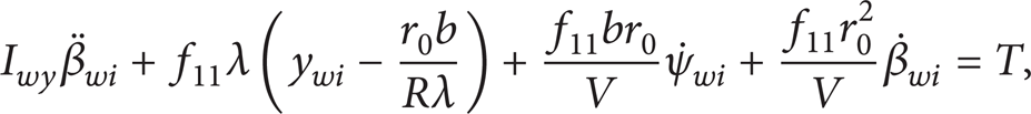
Wheelset lateral mode: while i = 1 or 2, j = 1; while i = 3 or 4, j = 2. Consider

Wheelset yaw mode: while i = 1 or 2, j = 1; while i = 3 or 4, j = 2. Consider

Right and left wheels relative rotating mode: i = 1, 2, 3 or 4. Consider
where
The equations of rail vehicle body and bogie frames can refer to the related literature. The parameters for the dynamic equations to represent a tramcar are given in Table 2.
Symbols and parameters of tramcar.

4.2. Motor Vector Control
Vector control and direct torque control are mature with position sensor for PMSM. But position sensors with high accuracy are necessary for PMSM control system to measure the correct angular position of rotor. And the control system would be out of work while encoders are broken. Vector control without position sensor based on the SMO is introduced in the traction control of PMSM.
The current SMO equations [10] (formula (4)) are used to estimate the angular position and angular speed of rotor in this work as follows:
where

i
s
, iα, and iβ: stator current, α, and β axes component of stator currents; L
s
: stator inductances; e
s
, eα, eβ: back (electric motive force) EMF, α and β axes components of back EMF; U
s
, Uα, Uβ, U
d
, U
q
: stator voltage, α, β, d, q axes components of stator voltage; k: negative constant; a: positive constant; θ, ω: angular position and angular speed of rotor; “
According to the formula (4), back EMF e s are estimated by stator voltage U s and stator current i s while the parameters of PMSM are given. After getting the back EMF e s , the angular position and angular speed of rotor would be obtained according to the following:

Back EMF is little to detect SMO, while the motor is of low speed or stand still. The rotor micromovement method is proposed in initial rotor position estimation [11]. A rotating voltage vector is imposed on the stator to produce the pulsating torque. Under the appropriate pulsating torque, rotor micro-movement would emerge and affect the current response. Hence, the rotor position information would be gotten from the voltage and current response of motor stator. Meanwhile, it should be notable that voltage and current are monitored all the time to evaluate the state of motor in practical traction converters.
According to the principle of sensorless vector control of PMSM based on SMO, the model of designed 60 kW disc PMSM is set up in MATLAB/SIMULINK to implement the traction control simulation. The angular speed and angular position of rotor are illustrated in Figure 2. During the simulation, the motor is under step load torque (from 500 to 1000 Nm in 0.3 s). In Figure 2(a), the real rotor speed follows the reference one well. And the error between the estimated and real speed is acceptable in practical application (maximum±0.2 r·min−1). In Figure 2(b), the estimated angular position is close to the real one. The simulation result shows that sensorless vector control of PMSM is accurate and stable based on SMO.

Speed and angular position of PSMS rotor.
4.3. Steering Control
As a simple and effective method, differential speed feedback control is applied in steering control of tramcar in this work. The wheel rotating speed is indispensable information in this system. Thus, speed sensors, like photoelectric encoder or hall speed sensor, are common in the control system of PMSM. But the wheel rotating speed information can be gathered without sensor, as the angular speed of motor rotor has been accurately estimated by SMO in the traction control. The wheel rotating speed is equal to the one of motor rotor in directly driven wheel solution of this work.
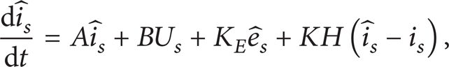
The traction and steering control strategies of bogie are shown in Figure 3 based on differential speed feedback. And four motors, M1, M2, M3, and M4 are supplied with power by separated traction inverter. Deviation coupling control is adopted between two motors in the same side. The longitudinal coupling synchronization would emerge under electrical control, which is similar to Combino bogie with the longitudinal mechanical coupling. To restore the centering on the straight track, motors of a wheel pair would synchronize under differential speed feedback control. While passing the curve line, the suitable rotating speed difference between a wheel pair would make the tramcar be with low attack angle and wheel/rail wear. The relative rotating speed

where Gω is a control function, simple proportional-integral control is used in this work; Δω* as control targets of speed difference would provide a compensation to make wheel run along the center line while passing the sharp curves [12]. Consider
The curvature data in formula (8) can be collected through a track database in the train and locating technology.
Scheme of steering control of power bogie.
The active steering control strategy makes the electrical coupler exist among motor directly driven IRWs. Therefore, this new coupled wheelset with an invisible coupler is named electrical coupled wheelset (ECW) in this work.
Higher acceleration and deceleration performance is needful in urban tramcar for frequent start and brake. Those characteristics of tramcar would require the traction motorto be fast dynamic response.
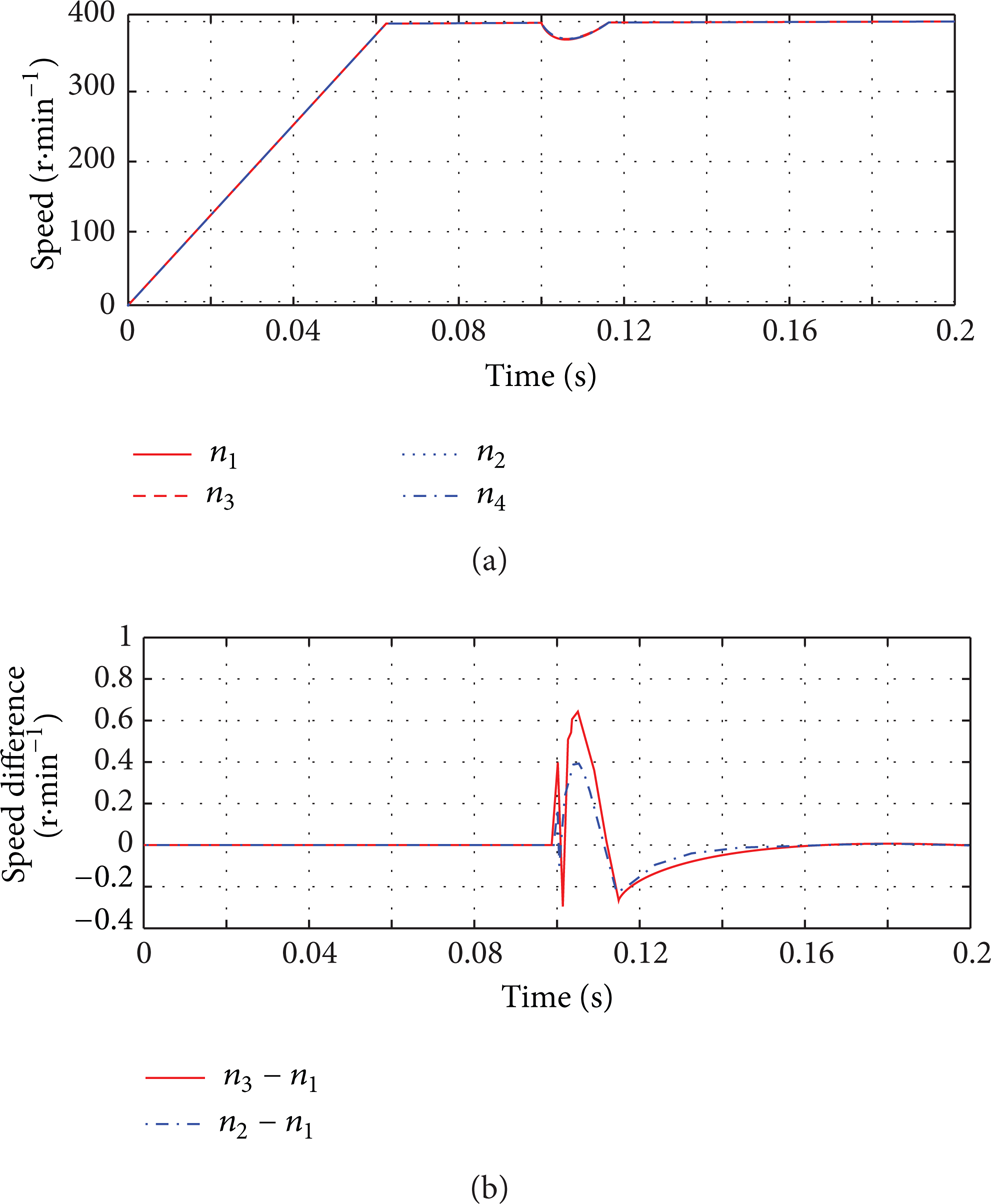
The dynamic speed responses (n1, n2, n3, and n4) of four motors in the bogie are shown in Figures 4 and 5 under the traction control and steering control, respectively. Motor 1 is under a step load (from 1000 to 1400 N·m in the 10 s), while the others are under a constant load (1000 N·m) in Figure 4. The simulation results indicate that four traction motors in the bogie are fast and stable to track the reference speed ω*. The output rotating speed of all motors would drop off at first and then track the speed command ω* to synchronize while one of the motors is under the step load. The given speed difference of two motors of a wheel pair is a step signal (from 0 to 5 r·min−1 in the 10 s) in Figure 5. The speed difference of both side motors follow up the designed differential speed signal Δω* = 5 r·min−1. Meanwhile, the same side motors still synchronous. Hence, IRW would turn into ECW under steering control system in order to improve the steering performance of tramcar. And the steering behavior of tramcar with ECW would be checked by simulation in the next section.
Synchronism of multi-motors under step load.

Speed difference of both sides motors under step speed command.
5. Simulation of Tramcar
The models of tramcar and traction motors are constructed in MATLAB/SIMULINK according to motion equation and control strategy. And as the classic mechanical coupled wheelsets, elastodamper coupled wheelsets (EDCW) [13] have been clearly confirmed in rail vehicles with better steering performance. So, a linear model of tramcar with EDCW (coupled stiffness K c = 1 MN/rad, coupled damping C c = 5 kN·m/rad) is set up as reference one to check the steering performance of tramcar with ECW.
The stability simulation results of tramcar in 70 km/h, with ECW or EDCW, are shown in Figure 6 after a 2 mm lateral pulse disturbance. It can be seen that the lateral displacement and yaw movement of the two type wheelsets decline with time and quickly disappear after the disturbance. Hence, the ECW or EDCW would run like solid wheelsets with self-steering ability.

Stability of tramcar with EDCW or ECW.
Curving performances of tramcar with EDCW or ECW are displayed in Figures 7 and 8 while passing a curve track (radius 200 m) in 70 km/h. The simulation results indicate that the lateral displacement of EDCW on the cure track is an approach to the pure rolling line like solid wheelsets. The yaw angle and lateral displacement of ECW are far less than EDCW as the control target is y w = 0. And the speed difference of ECW is close to desirable value Δω* = 0.243 rad·s−1 in formula (8). Besides, the wheel/rail lateral force of ECW is lower than the one of EDCW. And the power costs of motors in ECW are shown in Figure 9 to produce the steering ability. The maximum power consumption is less than 400 W in the active steering system.

Curving performance of tramcar with EDCW or ECW.

Wheel/rail lateral force of with EDCW or ECW.

Power consumption of ECW as electrical coupler.
6. Conclusion
In this paper, the disc PMSM directly driven IRW have been designed for low floor tramcar. The traction control and steering control of tramcar with disc PMSM directly driven wheels have been modeled and validated by simulation results. The findings can be summarized as follows:
Disc PMSM hung in bogie frame is suitable for directly driven wheel at outer side. Disc brakes attached to wheel would make the driven solution be more compact in axial size. These compact structures are important for the low floor tramcar, since driven solution must be placed under the floor of seats.
The motors are not only actuators of traction and steering control but are regarded as sensors to obtain the rotational speed of motor. Sensorless vector control of PMSM based on SMO is applied in traction control with robustness and stability. And the estimated angular speed of motor rotor in traction control without position sensors can use to the steering control of tramcar using differential speed feedback. Therefore, the active steering control can work without sensor or sensor with fault.
The tramcar with ECW is similar to the one with EDCW in the straight-line stability. However, the ECW are superior to EDCW in negotiation with low attack angel and lateral displacement near to zero under the active steering control. And low powers are the cost to produce the steering ability while passing the shape curve track.
Conflict of Interests
The authors declare that there is no conflict of interests regarding the publication of this paper.
Footnotes
Acknowledgments
The authors wish to acknowledge the support by the National Key Technology R&D Program of the Ministry of Science and Technology of China (2009BAG11B02), which make the work possible.