
Abstract
In order to realize a high speed and high accuracy prosthesis shaping equipment (PSE) control system, this paper proposes a new software-hardware architecture of a five-axis high performance NC system. The software part of the proposed architecture follows the rules of the hierarchy and modularity. The inheritance, scalability, and stability are ensured on the whole system and local parts. According to the idea of modular design, the framework uses the client-server mode in the communication and scheduling level. With this way, the reliability of the module management is ensured. The hardware part of the proposed architecture consists of two main parts: the controller and I/O module. The controller is based on FPGA and uses PCI bus and IPC interface. The I/O module is based on ARM + CPLD and uses CAN bus to communicate with the controller. This paper also studies some key problems such as the driving signal producing mechanism. The results of prosthesis shaping equipment prototype show that the system which uses the proposed architecture can reach the positioning accuracy up to 0.02 mm and 3D typical surface cutting accuracy up to 0.02 mm, and this accuracy level already leads similar products in market.
1. Introduction
Prosthesis shaping equipment plays a more and more important role in the modern life. Since the surface of denture is complex and individual, the traditional denture manufacturing method has a long cycle and poor accuracy. With the CAD/CAM technology developing rapidly, precision CNC milling machines began to be used for denture processing [1]. At present, a dozen of dental CAD-CAM systems are developed all over the world such as German CEREC, KaVo, French Sopha, and Dutch Cicero. Figure 1 shows the integrated flowchart of digital denture design and manufacturing process.

Denture design and manufacturing process.
Figure 2 shows the typical denture design and manufacturing process.

Denture design and manufacturing process.
In order to realize a high speed and high accuracy prosthesis shaping equipment control system, this paper proposes new software-hardware architecture of a five-axis high performance NC system.
The software part of the proposed architecture follows the rules of the hierarchy and modularity. The inheritance, scalability, and stability are ensured on the whole system and local parts. According to the idea of modular design, the framework uses the client-server mode in the communication and scheduling level. With this way, the reliability of the module management is ensured.
The hardware part of the proposed architecture consists of two main parts: the controller and I/O module. The controller is based on FPGA and uses PCI bus and IPC interface. The I/O module is based on ARM + CPLD and uses CAN bus to communicate with the controller.
This paper focuses on the design of the CNC system software-hardware architecture of the prosthesis shaping equipment and also studies some key problems of the system. Precision and efficiency are two main issues which are considered in this paper. Precision is related to residual error and scallop height. Processing efficiency depends on the complexity of the product, CNC software algorithm design, and hardware execution efficiency [2]. Since five-axis machining system movement is more complex, high performance NC systems design must coordinate planning software and hardware. In this paper, in order to improve the control precision and efficiency of denture processing, we introduce a new method to construct a whole architecture of a software-hardware platform.
The rest of the paper is organized as follows. In Section 2, we propose our software architecture of PSE. The hardware architecture of PSE is proposed in Section 3. The conclusion is given in Section 4.
2. Software Architecture of PSE
2.1. Software Architecture Design on System Level
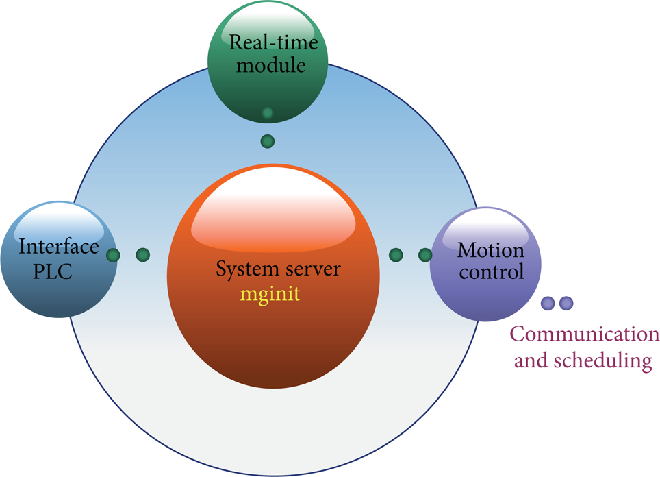
Our architecture of software design follows the rules of hierarchy and modularity. By these rules, the inheritance, scalability, and stability are ensured on the whole system and local parts. For the software platform, the PSE software system is constructed on the Linux + RTlinux + MiniGUI architecture. And it is divided into two parts under the system level: one is the user layer application module; the other is the real-time layer module. According to the idea of modular design, the framework provided by the MiniGUI client-server architecture is used in the communication and scheduling level. With this way, the reliability of the module management is ensured. According to the real-time control demand of the CNC system and the moving control processing unit requirements, the system is divided into five functional levels, which are the server process, interface process, motion control process, PLC process, and real-time module process.
The system of client-server architecture is shown in Figure 3. The function modules of the system communicate with the server, and the server is responsible for scheduling of each function module.
Client-server architecture of PSE.
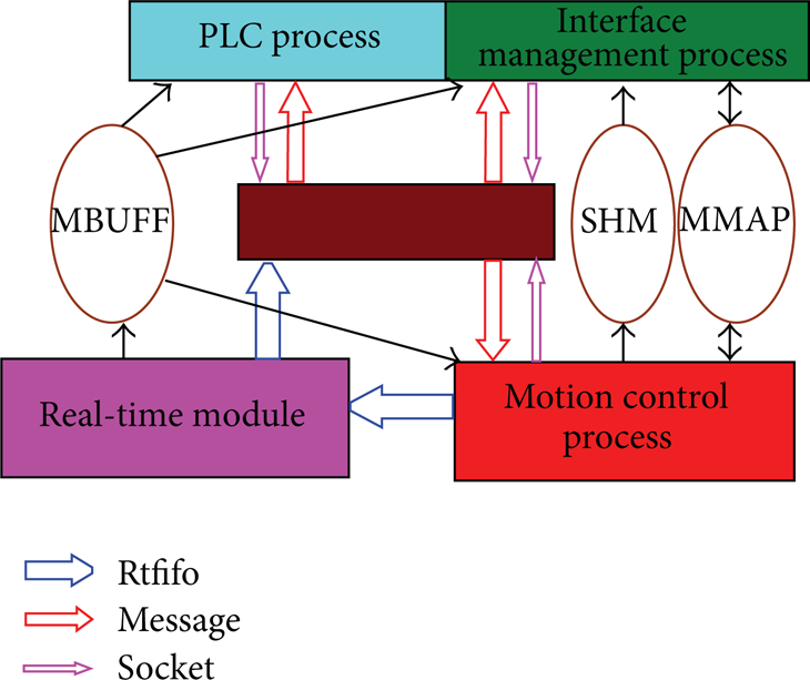
The communication mechanisms used in the system are mainly as follows: the message mechanism, shared memory, pipeline, and socket communication. In the application of message mechanism, the CNC system uses the Minigui Process message mechanism. It can provide the communication between different processes and the server to the client process. For the application of shared memory, the system uses three kinds of shared memory communication mechanisms: MBUFF, MMAP, and SHM.
MBUFF is a shared memory mechanism provided by RTlinux, and it is used for the real-time module and user level process information sharing;
MMAP is a file mapping shared memory mechanism; it is used for information sharing of system parameters;
SHM is the standard shared memory mechanism; it is used for information sharing between user level processes.
Pipeline communication mechanism is provided by the RTlinux. It is used for sharing real-time module and user level interprocess queue information. Socket communication adopts socket communication mechanism of Minigui Processes. It can achieve the communication between clients with the server conveniently.
Scheduling mechanism of our system mainly uses the protection mechanism. Each client process uses timing socket communication way for sending the survival report to the server. The server periodically checks the existence state of progress. Then the process scheduling is done in the right way according to the specific client state.
2.2. Client-Server Process Module
The client-server architecture consists of four main process modules, which are server process module, interface process module, motion control process module, and real-time process module.
2.2.1. Server Process (Mginit) Module
This process is the entrance process of Minigui Processes. After this process is started, the interface process (including PLC), motion control process, and real-time process are started one by one. Then, this process will become a daemon process, monitoring the changing states of PLC status of real-time module and survival state of each process. The process will always survive in the CNC system life cycle. It is not only in charge of providing communication server for each subprocess, but also in charge of the guard treatment for each subprocess.
2.2.2. Interface Process Module
Interface process is mainly in charge of all the keyboard operations, interface display, and maintenance. This process uses API and message processing mechanism provided by Minigui and also uses other subprocess communications and resource sharing to realize the real-time data display, program editing, file management, system parameters management, and other functions. PLC exists in the interface process in the system as a thread.
2.2.3. Motion Control Process Module
This process consists of compiling thread, velocity planning thread, and interpolation thread. It generates the machine motion control instructions by the corresponding asynchronous event thread scheduling mechanism.
2.2.4. Real-Time Process Module
It is a real-time module. It mainly uses the API function for various real-time modules provided by RTlinux to realize the machine logic control output and monitoring and realize the real-time output of motion control commands. This progress includes the routine instruction outputs, the thread processing real-time controlling, the PLC condition monitoring, and the control module.
2.3. System Communication Mechanism
Each module in system is interrelated. So the communication mechanism and data flow between modules must be designed comprehensively (Figure 5). In each module of the system, in order to illustrate the communication process between each module and the process through the message, pipeline and share memory more easily, here the various parts were divided according to Table 1.
Module Division.

The server sets up a communication mechanism of socket. It is used to monitor the messages from clients and is responsible for sending the global control messages to each module. The clients who send messages to server include the interface module, the PLC module, and the motion control module.
The server establishes the listening socket through the function mginit. At the same time, it registers the monitoring file descriptors, plcfifo_fd and errfifo_fd. With these two descriptors, the server can monitor the messages from the PLC pipe and the global error pipe. All the above work is done in time created by function mginit (mginit.c).
PLC pipe is created by promoter function mypci_init of the real-time module (pci_card.c) and is responsible for transferring data by the PLC layer (pci_card.c). Error channel is created by the OpenErrFifoForRead function (fifo.c).
When the client sends a request, the server will be the first to receive the MSG_FDEVENT message. At the same time, the server will differentiate the treatments based on the type of clients and the kind of messages.
3. Hardware Architecture of PSE
3.1. Hardware Architecture Design on System Level
Because the denture has small volume and complex surface, it may lead to overcutting in high speed machining due to high feedrate. To ensure the workpiece machining accuracy, the look-ahead speed control must be used on tiny path segments to realize smooth transition between the procedure sections as far as possible. After the toolpath file generated by CAD software is transferred to the CNC system it should pass five subsystems, respectively: NC codes compiling subprocesses, cutter compensation subprocesses, speed and acceleration or deceleration handle subprocesses, interpolation subprocesses, and control information output subprocesses.
The subprocesses coordinate through the signal variables, parallel operation, and forming data processing line (see Figure 6). After equivalent conversion, the control information output subprocesses output position control command to the NC National Key Technology R&D Program of China (2009BAI81B00) system underlying hardware equipment in strict accordance with the interpolation cycle interval. The machine moving axis is controlled by underlying hardware equipment. Due to the need for flexible machining process planning, it is not convenient to use speed control and interpolation module in control card that makes some control card like MCX314 control card and PMAC card cannot be used.
So far, various NC systems have been developed and researched. Wang et al. [3] have proposed a reconfigurable NC system based on the MPC5200 processor with embedded Linux operating system. As all tasks such as interpolation, interpretation, and HMI are arranged on a single CPU, the system application tends to be complicated and difficult to extend. Wang and Ni [4] have designed a reconfigurable embedded NC system based on ARM and MCX314, but the speed control and interpolation are unchangeable. Huang et al. [5] have developed the NC system based on DSP and FPGA; Liu et al. [6] have developed the NC system based on Nios II and FPGA, but they are not using bus technology, and their NC system lacks extensibility.
When analyzing the various five-axis machine control signals, we will find that control signals of five-axis servo driver are the most demanding real-time signals; at the same time the signals in the form and quantity are basically fixed. But other signals are not real-time requirements, such as handwheel, cooling, inverter, and other control signals, and the number of signals for different systems is not fixed. Therefore we adopted the hardware design that different types of signals are controlled by different boards; the NC system consists of two main parts: the master board and I/O board. The master board is the core component of the system, it is connected to the IPC through PCI bus, five-axis drive signals are generated by FPGA, and the master board also has pulse counting for encoder, timer interrupt, and communications’ functions. The I/O board finishes I/O expansion and analogue control functions; it uses the ARM + CPLD structure, and through a CAN bus to communicate with master board efficiently (see Figure 7).
3.2. Hardware Composition of PSE
Since the interpolation operation expenses can be easily met by ordinary IPC, we choose IPC software here for interpolation operation. By this method, it is easily to optimize the algorithm upgrade and simplify the hardware design (Figure 8). The FPGA of the master board uses Altera's Cyclone III FPGA family EP3C16Q240C8N, and the IPC interface uses PCI bus interface chip PCI9030 that is with high reliability and compatibility. PCI9030 supports the PCI v2.2 specification with 32-bit/33 MHz PCI interface enabling PCI burst transfers up to 132 MB/s, and the highest local bus operating clock is 60 MHz that breaks the bottleneck of data transfer, using PCI9030 erected efficient data transmission channel from FPGA to IPC. For the master board composition diagram see Figure 4. PCI9030 is responsible for converting PCI bus to local bus through the local bus to connect CAN bus controller SJA1000 and FPGA. There are four units in FPGA: pulse unit, serial unit, encoder unit, and timer unit. CAN bus and the direct input signal are used to expand connections inside the system. RS485/RS422 is used to communicate with servo driver, frequency inverter, or PLC. Five-axis drive control signals are composed of pulse signals and direction signals; the signal output form is differential signal. Five-axis encoder signal adopting the differential input form supports A, B, and Z three-phase detection. The following focus on the design of the key pulse unit within the FPGA, the development environment is the Quartus II 9.1, and the design language is Verilog HDL.
System process and communication. Rtfifo: Receive and transmit FIFO.

Module relation of whole architecture.

System information process scheme.

Hardware architecture.

Hardware composition of PSE.
Pulse unit is used to generate pulses in which frequency and number are specified. In order to satisfy the needs of variable speed continuous control, we use FIFO to achieve the ability of continuous output pulse with different frequency and quantity. The FIFO and PLL used in the pulse unit are designed by Quartus’ megaWizard tools. The working principle of pulse unit is shown in Figure 9.

Simulation of pulse waveforms. Clock enale: a enable signal to gate the main clock.
The control of pulse frequency is provided by the control of half cycle width. TCnt is pulse half cycle width counter whose initial value is TCnt_Cur. TCnt is automatically minus one at each cycle of 100 MHz clock. The initial value of TCnt is reloaded when TCnt reduced to 1, if the end is a positive half cycle that just needs to have a negative half cycle or just has finished the negative half cycle (i.e., a whole pulse transmission is complete) while NumCnt_Cur is not 0. NumCnt_Cur is the pulse number counter which is minus 1 at the falling edge of the output pulse. When width and number values of specified pulse are written to their FIFO, the first positive half cycle pulse is generated after five clocks of 100 MHz and then generates the negative half cycle pulse. The minimum of the half cycle width specified is five, namely, five reference clocks’ cycle. So the highest frequency is 100/5/2 = 10 MHz. Pulse simulation waveforms are shown in Figure 10.

The working principle of pulse unit.
3.3. Communication with CAN
CAN is the ISO international standard serial communication protocols, using short frame structure, arbitration, and error detection technology to ensure real-time data transmission and high reliability. CAN is suitable for CNC machine tools with high interference environments [7]. CAN communication circuit is shown in Figure 11; the master board uses a separate CAN controller SJA1000 and I/O board uses ARM processor built-in CAN bus controller. Host uses user defined communication protocol communications with the I/O board.

CAN communication mechanism.
We communicate by the extended data frame. The message ID is 29 bits and data packets are 8 bytes. A total of 12 commands are defined, the command code: 00H–0BH; each command has a number of features to distinguish through the function code. The function description of each bit in the message ID is shown in Figure 11. For example, there are five servo drive control signals: Servo-on (0:SON), Gain changing selection (1:CDP), Emergency stop (2:EMG), Reset (3:RES), and Speed selection (4:FAST). The servo control command code is 4, the highest bit of 8-bit function code is signal vale (0 or 1), and the remaining 7-bit binary values indicate which signals to control. For instance, 1000011 means that the reset signal (RST) is set to 1.
In order to rapidly respond to host commands, we use interruption program handling CAN communication in ARM software. To speed up command parsing speed, command codes and function codes are coded from 0 in a row. In CAN communication program module, the function pointer array is used to achieve parsing of the command rapidly and call function quickly. This uses a command function pointer array cmd_call []; element of the array is a pointer to the command function. Each command has multiple functions; for each command to establish a functional array of function pointers, cmd0_call [], cmd1_call []…, the array element is a pointer to point to the performance function. The processes call the performance function through array of function pointers shown in Figure 12.

CAN command analysis and function calling.
4. Conclusion
This paper proposes a five-axis software-hardware platform for prosthesis shaping equipment, adopting an open system structure and a modular design method. The prototype of our prosthesis shaping equipment based on the software-hardware platform is showed in Figure 13.
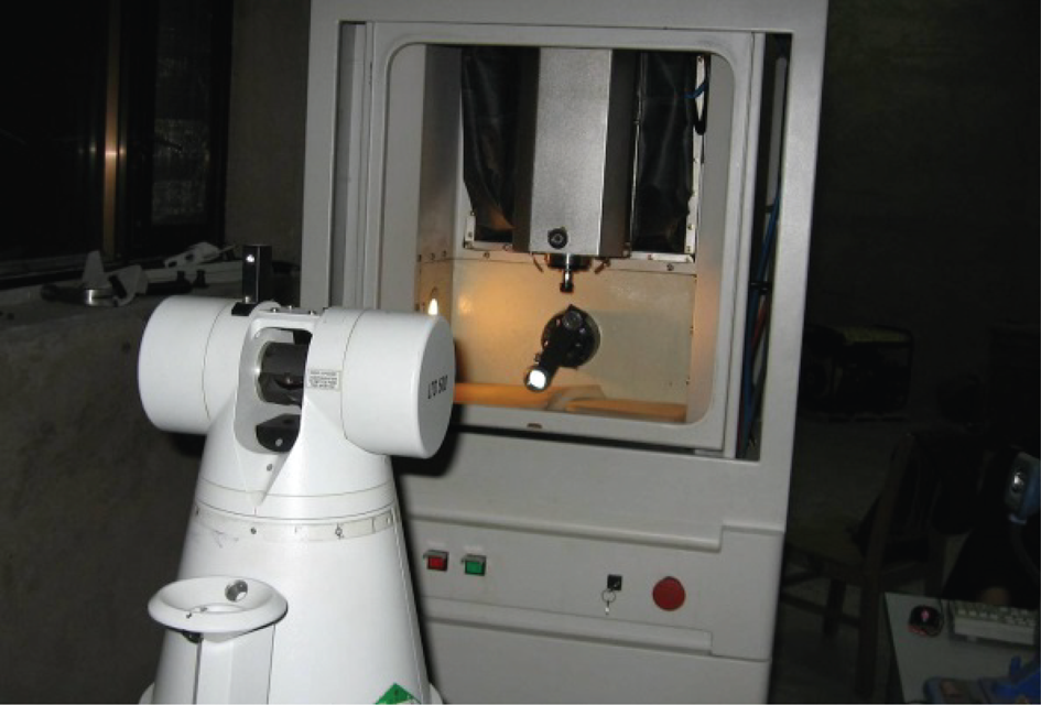
Prototype of our prosthesis shaping equipment.
It has rich resources, is highly customizable, and has high control precision. Using this software-hardware platform, the PSE system can reach the positioning accuracy up to 0.02 mm, 3D typical surface cutting accuracy up to 0.02 mm, quickest cutting speed up to 6000 mm/min, and zirconia material single tooth processing time less than 20 minutes. The system performance already leads similar products in market.
Conflict of Interests
The authors declare that there is no conflict of interests regarding the publication of this paper.
Footnotes
Acknowledgments
This work is funded by National Natural Science Foundation of China (no. 51375016) and the Great Wall Scholars Program of Beijing (no. CIT&TCD20140302).