
Abstract
Flow assurance issue in subsea pipelines arises mainly due to hydrate plugs. We present a new line-heater for prevention of hydrate plug formation in subsea pipelines. The line heater has modular compact design where an electrical heater and a swirl generator are embedded inside the housing pipe so that the stream can be heated efficiently and homogeneously. In this paper, flow and heat transfer characteristics of the line heater are investigated numerically, with a particular emphasis on the mixing effect due to the swirl generator.
1. Introduction
In offshore plant systems for oil and gas production, flow assurance has arisen as the most crucial issue regarding safety and productivity of the system [1]. Generally the flow in subsea pipeline of the offshore subsea plant system consists of water, oil, natural gas, and sand (or mud), and the term flow assurance refers to ensuring successful flow of the mixture stream through the pipeline. Flow assurance issue in subsea pipelines arises mainly due to gas hydrate plugs which block the pipeline. Hydrate plug can cause serious damage to the system, which is directly related to safety issue, and the production process might be held due to hydrate plugs. Therefore, huge amount of ecomonic cost is involved in removing or preventing hydrate plugs.
Hydrate plug formation is a complex process which depends on hydrodynamic and thermodynamic conditions of the flow, and details of the plug formation mechanism are yet to be investigated. Figure 1 shows a schematic diagram of offshore plant and possible points of hydrate plug formation [1]. In general, the temperature of seabed is around 4 degree Celsius, and thus the flow in subsea pipelines cools rapidly. In this low temperature condition along with high pressure in the pipeline, gas hydrate begins to form on the surface of emulsified water droplet. The hydrate film thickens slowly, converting water droplet into hydrate particle. Wet hydrate particles which have water remaining inside are adhesive with each other and thus they can agglomerate, resulting in hydrate plug. Due to complicate nature of the hydrodynamics and thermodynamics of the mixture with the hydrates, understanding the flow characteristics still remains one of the most challenging issues [2].

Offshore plant system and possible points of hydrate plug formation in subsea pipeline.
There are several approaches to prevent hydrate plug formation [1, 3–8]. By injecting chemical inhibitors such as methanol and glycol at the well head, hydrate formation can be basically prevented. In this approach, however, the inhibitor should be separated from the stream on the platform, and running costs are relatively high as substantial amount of chemicals are involved. Thermal insulation of the pipeline reduces heat loss of the stream and thus can prevent hydrate formation. Pipe-in-pipe (PiP) and buried pipe are representative examples of this approach and heat transfer characteristics of the buried pipe has been investigated analytically and numerically [7]. In addition, recent experimental investigation has shown that the heat transfer characteristics of the subsea pipeline is significantly affected by the buried depth [8]. Running cost of this approach is considerably lower than that of inhibitor approach. However, this passive approach may not be sufficient for very long pipelines since thermal insulation cannot be complete in practice. For long step-outs of offshore field development, therefore, heat should be supplied to the pipeline by some active manner.
Recently, electrical heating systems for subsea pipeline have been developed by several oil companies [3, 5]. By applying alternating electric current through pipeline, the pipeline can be directly heated due to resistive heating, which is commonly termed as direct electric heating (DEH) method. The pipeline is covered with thermal and electrical insulater, and electric power is supplied via piggyback cable which is mounted on the pipeline (see Figure 2). There is another method called electrically trace heated pipe-in-pipe (ETH-PiP). Basically, ETH-PiP is PiP having electric heater cable coiled around inner pipeline in a helical manner (see Figure 2). This system was recently installed in offshore field for tests and the performance was found to be successfull for industrilization of the system.

Schematics of direct electric heating method (a) and electrical trace heating pipe-in-pipe method (b).
In this paper, we present a new line-heater for flow assurance in subsea pipelines. Main feature of the line heater is that an electrical heater and a swirl generator are located inside the pipe so that the stream can be heated efficiently and homogeneously. In addition, the line heater has modular compact design and thus it can be installed locally at particular points of possible hydrate plug formation, which would be efficient in terms of the energy consumption and maintenance. We investigate flow and heat transfer characteristics of the line heater numerically in this study. In Section 2, details of the line heater are introduced. Governing equations and numerical method are explained in Section 3 and results are presented in Section 4.
2. Line Heater
In subsea pipelines, there are several points where hydrate plug might be formed as shown in Figure 1. By introducing line heaters locally near these points, hydrate plug formation can be prevented. Figure 3 shows a schematic diagram of the line heater which is installed in between two pipelines via flanges. The line heater consists of a cylindrical cartridge heater, a swirl generator (namely, a swirler), and a housing pipe. The cylindrical cartridge heater is located inside of the swirler, and the lead wires are connected through the L-shape connection.

A schematic of line heater installed in pipeline.
The swirler induces three-dimensional complex flow field which enhances heat transfer from the cartridge heater, and thermal mixing of the stream can be significantly improved as well [9, 10]. In addition, hydrate agglomerates already formed upstream can be dispersed and removed by viscous force and applied heat along the line heater.
Details of the line heater are shown in Figure 4. The swirl generator consists of a cylindrical shell and four tapes which are attached on the cylindrical shell with a twisting angle of θ. The cartridge heater is inserted in a cylindrical cavity inside the swirler. The pipe has inner diameter of D (the pipe thickness is neglected in Figure 4). The inner and outer diameter of the cylindrical shell of the swirl generator are c and d, respectively, and the tapes have a thickness of t. The cartridge heater has diameter of c.

Schematics of a line heater with a swirl number of 0.14.
The geometrical parameters used in this study are L/D = 10, d/D = 0.6, c/d = 0.7, and t/D = 0.02. The inlet and outlet are located at z = 0 and z = L, respectively. A swirl number S which characterizes the degree of swirl is defined as [11]
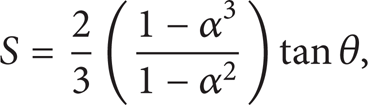
where α = d/D. We study three cases of swirl numbers of 0.14, 0.43, and 0.74 (see Figures 4 and 5). As swirl number increases, the flow will become more complicated and thermal mixing will be enhanced, while the pressure loss increases.

Line heaters with swirl numbers of 0.43 (a) and 0.74 (b).
3. Numerical Analysis
Flow and heat transfer characteristics of the line heater are investigated numerically. The cartridge heater is assumed to maintain constant temperature and the housing pipe is assumed to be insulated. The flow is assumed to have uniform constant temperature at inlet (z/D = 0). As shown in Figure 6, one quater of the swirler and a channel therein are selected as a computational domain. The computational domain consists of two subdomains Ω = Ω s ∪ Ω f where Ω s represents the solid region and Ω f represents the fluid region. There is an interface Γ f = Ω s ∩Ω f , and five different boundaries of pipe wall Γ w , mid-plane of tapes Γ s , cartridge heater surface Γ c , outlet Γ o , and inlet Γ i (which is not shown in Figure 6 and is located at the other side of the computational domain). We will solve flow and heat transfer problems in the fluid region Ω f and heat transfer problem in the solid region Ω s . The computational domain is discretized by 1575000 hexahedron elements and 1621711 nodes and Figure 6 shows a close-up view of the mesh system. This mesh system is selected after mesh convergence tests which will be discussed later.

Close-up view of a computational domain (a) and mesh system (b).
We solve the flow and temperature fields at steady state. Governing equations of Navier-Stokes equations and energy conservation equation are written as follows:

where
Boundary conditions are as follows:
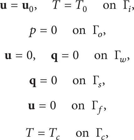
where
List of boundaries and corresponding boundary conditions.

The Reynolds number is defined as
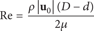
which represents the ratio between inertia and viscous forces of the flow. The Péclet number is defined as

which represents the ratio between advection and diffusion of the heat energy. In this study, the inlet velocity (
Of particular interest of this study is the mixing characteristics in the fluid region Ω f . In this regard, species transport problem is solved in the fluid region for mixing visualization purpose [12]. The species concentration c is an artificial quantity for mixing visualization and it does not alter the physical property of the fluid. We solve a simple advection equation of the species concentration c as follows:

where c varies from zero (black fluid) to unity (white fluid). We introduce a dyed species on the half of the inlet as shown in Figure 7.
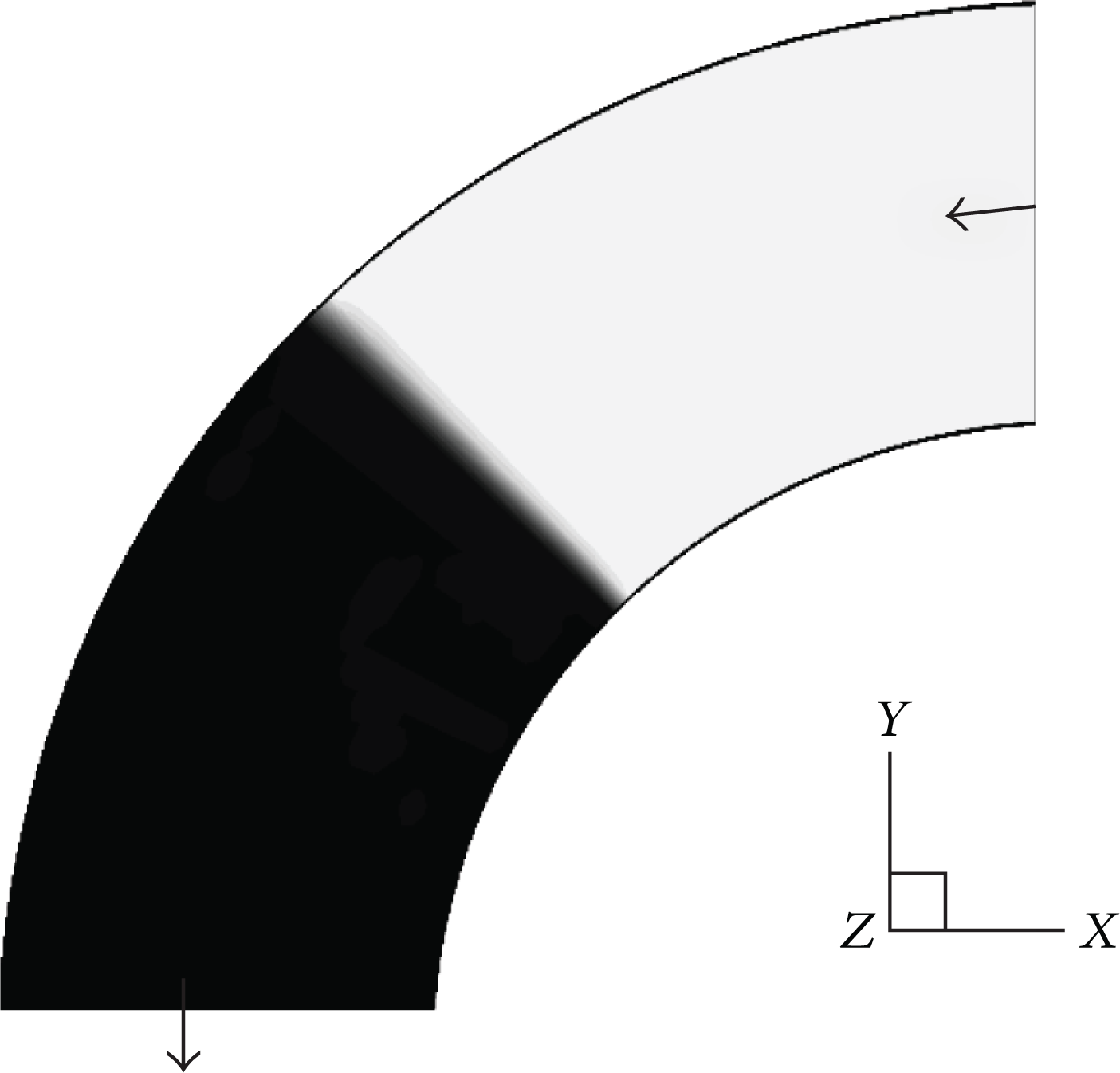
Cross-sectional species distribution at the inlet for mixing characterization. Arrows indicate the twisting direction of the tapes observed from the reference frame.
The degree of mixing is quantified based on a standard deviation σ of the species distribution as follows:
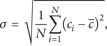
where N is the total number of data points, c
i
is the concentration at point i, and

where T
i
is the temperature at point i and
All governing equations with the initial and boundary conditions mentioned above are solved by a commercial CFD software ANSYS Fluent which is based on a finite volume method. As mentioned before, the computational domain is discretized by hexahedron elements which are aligned with the boundaries as shown in Figure 6. Mesh convergence test is carried out using four different mesh systems and the results are presented in terms of the standard deviation at the outlet in Table 2. According to the mesh convergence test, mesh system M3 results in an almost converged solution with an appropriate amount of the computational cost. Therefore, mesh system M3 is used for all results in the following.
Mesh convergence results in terms of the standard deviation at the outlet. Swirl number = 0.74 and Reynolds number = 1011.

4. Results and Discussion
The mixing characteristics are discussed first. Figures 8–10 show cross-sectional species distributions for various Reynolds numbers and swirl numbers along the downstream of the line heater. For the Reynolds number of 10 (see Figure 8), the cross-sectional flow is characterized by a simple rotational flow. One can observe that the cross-sectional configuration is rotating in a clock-wise direction as z/D increases (i.e., along the downstream). This rotational flow becomes more significant as the swirl number increases.

Cross-sectional species distributions for the Reynolds number of 10.

Cross-sectional species distributions for the Reynolds number of 101.

Cross-sectional species distributions for the Reynolds number of 1011.
As the Reynolds number is increased to 101 (see Figure 9), centrifugal force due to rotation of the frame becomes significant particularly for high swirl number case. As shown in the case of swirl number of 0.74, the centrifugal force induces a radial flow, which results in two counter-rotating flows. For a low swirl number of 0.14, this effect is not so significant. Further increase of the Reynolds number to 1011 (see Figure 10) results in a very complicated flow field, especially for swirl number of 0.43 and 0.74 case. The mixing enhancement is notable for the high swirl number of 0.74.
Shown in Figure 11 are mixing quantification results based on (7). In Figure 11(a) which is the case for swirl number of 0.74, the standard deviation decreases almost linearly for z/D ≥ 2, and the decreasing slope becomes larger as the Reynolds number increases. It should be mentioned that the standard deviation remains almost unchanged in the region of z/D ≤ 2 where the entrance effect is dominant. The standard deviation at the outlet for different swirl numbers is shown in Figure 11(b). For the swirl number of 0.14, the mixing enhancement as the Reynolds number increases is almost negligible.

Standard deviation of species distribution (a) along the downstream for swirl number of 0.74 and (b) at the outlet.
Figure 12 shows cross-sectional distribution of the temperature at the outlet of the line heater. At low Re of 10, conduction dominates the heat transfer and thus overall cross-section is heated more uniformly than the other cases of higher Re. The effect of rotational flow as S increases can be also observed. At Re of 101, the flow is heated only around the swirler when S = 0.14. As S is increased, however, one can observe the radial advection enhancing the thermal mixing. At high Re of 1011, axial flow dominates the heat transfer thus most region of the cross-section could not be heated uniformly, though the radial advection effect can be observed as S increases.

Cross-sectional temperature distributions at the heater outlet.
Thermal mixing of each case is compared quantitatively in terms of the standard deviation (see (8)) in Figure 13. In general, the standard deviation σ T decreases as the swirl number S increases, which indicates that the swirler enhances the thermal mixing as expected from the mixing analysis results of Figure 11. Relatively low σ T at low Re reflects diffusional mixing by conductive heat transfer, while axial advection at high Re results in decrease of σ T .

Standard deviation of temperature distribution at the outlet.
Figure 14 shows overall heat transfer coefficient (U) and friction coefficient (f) of the line heater. The overall heat transfer coefficient is defined as
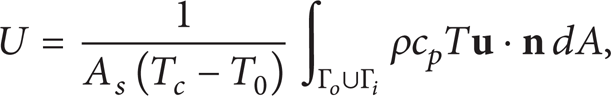
where A
s
is wetted surface area of the swirler and

where ΔP is the pressure difference between the inlet and the outlet and D h is the hydraulic diameter of the channel.

(a) Overall heat transfer coefficient and (b) friction coefficient.
Since the flow is developing flow with the entrance effect involved in, the overall heat transfer coefficient increases with Re in this laminar flow regime. As the swirl number increases, heat transfer is enhanced due to thermal mixing effect especially at Re > 20. The friction coefficient is almost inversely proportional to Re for small swirl number of 0.14 since the axial flow is dominant than the swirl effect. As the swirl number increases, the friction coefficient increases, which is especially pronounced at high Re.
5. Conclusion
In this paper, we have introduced a new line-heater which can be installed locally at subsea pipelines for prevention of hydrate plug formation. Unlike the previous heating methods, a cartridge heater and a swirl generator are embedded inside the pipe so that the flow can be heated efficiently and homogeneously. To understand the basic flow and heat transfer characteristics of the line heater, we have carried out numerical analysis with a particular emphasis on the thermal mixing effect.
In general, mixing is enhanced as the swirl number and the Reynolds number increase. At low Re ≤ 10, the swirler induces simple rotational flow in the channel cross-section, and the rotational flow becomes more apparent as the swirl number increases. This rotational flow is not effective for mixing, but thermal diffusion results in relatively uniform temperature distribution. At Re ~ 100, centrifugal force begins to affect the flow, which induces radial flow and thus enhances the mixing. Further increase of Re to around 1000 results in a very complicated flow field and efficient mixing. As a result, the overall heat transfer coefficient increases with the swirl number and the Reynolds number.
The line heater is expected to be one essential component in subsea pipelines for long step-outs of offshore field development. Although this study is limited to fundamental understanding of the flow and heat transfer characteristics, experimental study in laboratory scale is in progress, which will be presented in a separate publication.
Conflict of Interests
The authors declare that there is no conflict of interests regarding the publication of this paper.
Footnotes
Acknowledgment
This work was supported by the Industrial Infrastructure Program of the Korea Institute for Advancement of Technology (KIAT) Grant funded by the Korea government Ministry of Trade, Industry and Energy (N009700001).