
Abstract
This study presents electromagnetic-controlled thermal storage (ECTS) that can be directly implemented in strategies of low-temperature waste heat recovery for energy-consuming equipment. A magnetic nanofluid (MNF) prepared from fine iron ferrite ferromagnetic particles is recommended as a latent heat medium (LHM). During electromagnetic induction, local flow fluctuations are generated and thermal convection in the MNF can be enhanced. The achieved results demonstrated that ECTS has a wide operational range and an optimum storage efficiency of 84.46%. Thus, a self-perturbation mode used to enhance thermal energy transportation can be designed for numerous waste heat management applications.
1. Introduction
The need to curtail global warming has created a demand for green technology innovation and implementation, especially for heat conservation [1–3]. It resulted that thermal storages have been widely used in several engineering fields. Because of the discrepancy between thermal energy supply and energy demand, developing adequate thermal energy storing methods is required. Thermal storage has received a considerable amount of attention recently because of the vital role it plays in thermal energy applications such as solar thermal power plants [4] and energy efficient buildings [5, 6]. Similar problems arise when waste heat availability and utilization periods are different. Generally, thermal storage techniques can be classified into two categories: sensible heat and latent heat [7, 8]. Sensible heat is defined as the quantity of thermal energy that is stored in a storage medium without changing the phase of the medium. This causes thermal stratification and reduces storage efficiency. However, because it provides a high energy storage density, latent heat thermal storage is a particularly attractive technique in contrast to conventional sensible thermal energy storage systems. Latent thermal storage systems require a small medium weight and volume for a given amount of energy [9]. It has drawn a considerable amount of interest in recent times because of its operational advantages. Typically, the performance of latent heat thermal storage is superior to that of sensible heat thermal storage.
Low-temperature latent heat mediums (LHMs) are mainly used in waste heat recovery systems and buildings, whereas high-temperature LHMs are used in solar power plants and other high-temperature applications [10–12]. Low thermal conductivity, which prolongs the charging period, is considered the main disadvantage of LHMs. Therefore, extensive investigations are required to improve the thermal response of LHMs by using advanced materials with excellent thermophysical properties. Because liquid-vapor transitions transform at a higher heat than solid-liquid transitions, liquid-vapor LHMs can be introduced in thermal storage applications. To limit the operational conditions under low saturated pressures, a suitable liquid-vapor LHM filled into a vacuum storage chamber is believed to have high thermal conductivity and latent heat of vaporization, which can enable conducting latent heat and sensible heat absorptions simultaneously.
Magnetic nanofluid (MNF) was chosen as a LHM for its superior electromagnetic and thermal properties, which has been widely validated for electronic, optical, and catalytic applications. Recently, MNF studies have incorporated nonpotential bulk forces in magnetically nonuniform fluids and yielded new promising application designs [13–15]. MNF magnetization greatly depends on temperature when heated in a nonuniform magnetic field that influences magnetic convection, as well as natural convection caused by an inhomogeneous distribution of fluid density in a temperature gradient. Thermomagnetic energy conversion using MNF proposed during the early stage of magnetic fluid research can only be realized by synthesizing fluids that have a large pyromagnetic coefficient. However, the permanent magnetism of nanoparticles in MNF changes to induced magnetism and the aggregation of fine particles in MNF has a predetermined Curie temperature. Below this temperature, electromagnetic effects can typically enhance thermal convection in MNF. Many researchers have studied the latent heat transfer of MNF and shown that the presence of nanoparticles in liquid enhances critical heat flux [16–18]. Therefore, by applying the appropriate design, MNF can be used to manage low-temperature waste heat sources more effectively. The proposed thermal storage is manipulated using an electromagnetohydrodynamic (EMHD) method, can be easily integrated into modular architecture, and is flexible in practical applications.
2. Preparation of MNF
The magnetic nanofluid (MNF) is a type of smart material that includes suspended monodispersed superparamagnetic nanoparticles and can be inducted by electromagnetic fields. With a high specific heat capacity and liquid-vapor latent heat, MNF meets the requirements for a LHM. Using a chemical coprecipitation technique in which iron ferrite fine ferromagnetic particles are synthesized, MNF was prepared. The first step required selecting the materials to be dissolved in deionized water, which were FeCl2·4H2O and FeCl3·6H2O. At a mixed ratio of 1: 3, the Fe2+ and Fe3+ solutions were stirred at a rotational speed of 500 rpm. Then, the NaOH solution was added into the Fe2+/Fe3+ solution at the same stirring rate. The chemical reaction of the preparation is expressed as

Following the precipitation reaction, the final pH value of the mixed solution must be controlled until it reaches 8.0. After washing and centrifuging the solution with deionized water, the Fe3O4 can be reserved. Consequently, the MNF can be fabricated using nanometer-sized Fe3O4 particles (Curie temperature ~860 K), ammonium oleate as a surfactant, and deionized water as a solvent. The surfactant agent coated with magnetic particles was used to prevent aggregation in production. The average size of the MNF nanoparticle, which was determined using a high-resolution transmission electron microscope (H7000, Hitachi, Ltd., Japan), is 26±2.5 nm. The hysteresis loops for 4.5 M MNF used, measured using a vibrating sample magnetometer (7300, Lakeshore Cryotronics Inc., USA), exhibit a satisfactory superparamagnetic behavior of 14.5 emu/g at 300 K and ±15000 Oe (Figure 1).

MNF magnetic hysteresis loops measured under an external magnetic field at room temperature by VSM. The insert TEM image indicates the average size of the MNF nanoparticle is 26±2.5 nm. H represents the applied magnetic field strength and M represents magnetization.
To estimate the stored thermal energy in ECTS, the thermophysical properties of MNF, such as thermal conductivity, viscosity, density, and specific heat capacity, must be determined. Measured using a hot wire technique, the thermal conductivity of the MNF was 2.7 W/m·K. Moreover, the viscosity of the MNF, measured by a viscometer, was 6.63 × 10⁻³kg/m·s. Both the density and specific heat capacity of the MNF were linearized relative to the nanoparticle volumetric concentration [19], which is represented as

where the subscripts nf, bf, and np represent nanofluids, base fluid, and solid particles. In this study, the base fluid was deionized water (ρ bf = 1000 kg/m3, C P,bf = 4.2), the nanoparticle was made of magnetite (Fe3O4), and the volumetric concentration of the nanoparticle, φ, was 0.032±0.001. The density (ρ np ) and specific heat capacity (C P,np ) of the magnetite were 5180 kg/m3 and 0.67 kJ/kg·K, respectively. Therefore, ρ nf and C P,nf can be obtained as mean values of 1133.26 kg/m3 and 4.085 kJ/kg·K.
In fact, all the thermophysical properties of MNF were varied during the ECTS operation, causing the uncertainties in evaluation of stored thermal energy. However, the majority of MNF maintained liquid state and only few of them turn into vapor phase in our studies. Thus, an acceptable way to evaluate the thermal capacity was generally used by constant properties.
3. Description of the ECTS
The majority of thermal storages utilize an active control method to transfer thermal energy. A pump design, which uses a flowing work fluid to transfer thermal energy from a high-temperature heat load to the storage chamber, is usually included. An electromagnetic valve is also used to change flow path of the working fluid to ensure that stored energy can be released to and used by a heat sink. Therefore, the charge and utilization ability of these thermal storages rely on the system piping design. The heat supply side and the heat utilization side of the thermal storage cannot operate simultaneously during the energy utilization.
The proposed ECTS featuring the thermosyphon characteristics of two-phase heat storage comprises a loop heat pipe and a chamber design. The loop heat pipe consists of a disk-shaped evaporator, a sinuous condenser, and liquid and vapor transport lines, which form a closed loop. The sinuous condenser loop embedded in the storage chamber with a large heat exchange surface was designed to efficiently transfer the thermal energy to the MNF. The entire loop was composed of copper tubing with an inner diameter of 3 mm. Moreover, a nickel-sintered porous wick self-driving design was located within the evaporator. A thermoelectric module with a maximum conversion rate of 7% can be mounted on the bottom of ECTS for utilizing the stored thermal energy. When the ECTS undergoes a simultaneous heat charge and utilization mode, two electromagnetic valves open. One of the valves is used to enable MNF to flow into the bottom layer and release thermal energy to the thermoelectric module. The other valve, which is on the opposite side, is used to pump the MNF returns to the storage chamber, resulting in flow circulation. To ensure ECTS performance, the storage chamber structure should meet flexibility, strength, corrosion resistance, and thermal stability requirements and provide a sufficient surface for heat transfer. A sealed hexahedral glass container with main dimensions of 85 mm × 610 mm × 760 mm has a vacuum compartment enveloping a storage chamber and an electromagnetic design. This electromagnetic design deployed at both sides of the storage chamber consists of five 5000-gauss external strength rated electromagnets and each of them carries a current of 0.4 A. Moreover, a flexible insulation layer with a low thermal conductivity (0.037 W/m·K) is attached on the inner wall of the storage chamber. To avoid thermal stratification, four porous ceramic plates (pore diameter: 28±1 μm) are used to separate the storage chamber into five compartments. The configuration of the ECTS is shown in Figure 2(a).

(a) ECTS schematic design. (b) Configuration of experimental setup and measuring points. Ts1 and Ts2 are temperatures at both ends of condenser loop. T1 to T5 are temperatures at turns along condenser loop. Ta to Tf are temperatures within storage compartments.
To prevent the nanoparticles from aggregating, the storage chamber must initially be vacuumed to reduce the saturated MNF temperature. Thus, the MNF can efficiently absorb, store, and release heat under a low transition temperature. In this study, an 85±1% volume ratio of the storage chamber was filled with MNF from a vacuum state, and the rest was left as a gap for pressure adjustment. Through the staggered deployment of electromagnets, some local fluctuations can be controlled in the compartments. From the perspective of hydrodynamics, this induction exciting thermal convection was governed by the Navier-Stokes equations, Maxwell equations, and Ohm's law.
4. Experimental Setup
Seven measuring points along the condenser loop (five at turns and two at both ends) and six at the thermal storage compartments were chosen. Moreover, all the temperature responses were measured using carefully calibrated K-type thermocouples. The heat load was constantly applied on the evaporator using a DC power supply unit (PW-3033, PINTEK Inc., Taiwan) at a power ranging from 100 W to 1000 W. The loop heat pipe was embedded under the vacuum before being filled and was able to hold a vacuum level of 10−3 Torr. Deionized water was the working fluid, and the fill ratio of the loop heat pipe ranged from 30% to 80%. The fill ratio determines the amount of space the fluid can occupy relative to the amount of space available in the loop. It is defined as the ratio of fluid volume to entire loop volume. A high-speed data acquisition system (DL 750, YOKOGOWA Inc., Japan) with a 5 Hz sampling rate was used to measure the temperature responses. The experimental setup is shown in Figure 2(b). All the experiments were conducted for exactly 3 hours. Furthermore, air temperatures were maintained at 20±0.1°C using an air conditioner. The total stored thermal energy was estimated by measuring the accumulation of stored thermal energy in the compartments, which is represented by
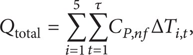
where ΔT i,t is the temperature difference between the loop and the wall in a respective compartment at time t. Total operation time is represented by τ. Therefore, ECTS charge efficiency can be evaluated as

where Qinput is the total heat load applied on the evaporator during heat charge.
5. Results and Discussion
The developed ECTS introduces MNF as the LHM in waste heat recovery for energy-consuming systems. The core ECTS operation includes heat charge and heat utilization. With electromagnetic induction, the MNF flow can be transiently changed by the Lorentz force, and thermal instability in MNF can be actively enhanced.
Figure 3(a) shows the operational mechanism of the evaporator in this ECTS design, in which the heat load is conducted through a combination layer of liquid and porous wick and then removed in the form of latent heat through evaporation from the menisci, which formed at the surface of the porous wick. Following a one-way circulation, the rectangular grooves on the wick were used to guide the flow. In addition, the disk-shaped porous wick was composed of sintered nickel powder with a permeability of 1.1 × 10⁻¹¹m2. The porosity of the wick, defined as the ratio between the void and the bulk volumes, is controlled at 0.63. The average pore dimension of the porous wick was 15±2 μm, as shown through scanning electron microscope (JSM-6500F, JEOL Ltd., Japan) image in Figure 3(b). By controlling well surface roughness with well-designed microstructures, the effects of the vapor blankets on the wick can be minimized. Consequently, durable and steady high-pressure vapor grooves drive the vapor forward to the condenser without interface friction losses of phases. The porous wick in the evaporator is crucial for providing high specific capillary pumping, which can increase the effective evaporation surface area and significantly reduce the thermal resistance along the loop. When the heat load is applied on the evaporator with the specially designed porous wick, the liquid working fluid can be evenly vaporized inside and the circulation of the working fluid is driven.

(a) Evaporator operational mechanism. (b) Configuration and SEM image of the porous wick.
A demonstrated heat load of 700 W with no failed start-ups was obtained at 35%–80% fill ratios, and more thermal energy can be stored at 40%–80% fill ratios. However, the ECTS showed substantial failure at low fill ratios above the heating condition. This suggests that the fill ratio of the loop heat pipe is highly related to ECTS performance. The variations of stored thermal energy with different heat loads and fill ratios are shown in Figure 4. The loop heat pipe fill conditions ranging from 35% to 80% can always be used to start the ECTS under heat loads ranging from 300 W to 700 W, and the optimal value for the maximal storage amount of thermal energy was 60%. At this optimal fill ratio, the latent heat of vaporization in pipe flow is always higher than those at other fill conditions within the heating range. Under the electromagnetic fields, local flow fluctuations generated in MNF enable the condenser loop to release thermal energy, resulting in greater storage capacity. Therefore, thermal stratification, the formation of layers of different temperatures in a storage chamber, should be avoided. In addition, the ECTS cannot be started by undergoing latent heat transfer at 100 W. This extremely low heat load causes tiny vapor pressure to drive the pipe flow and no thermal energy is stored. ECTS can only be operated at a fill range from 45% to 65% at 200 W. Under this heating condition, the pipe flow tends to dry out with low fill ratios (i.e., <45%) and shows poor thermal storage independent of 45%–65% fill ratios. However, ECTS with an 800 W heat load can only be operated until the fill ratio reaches 45% and has optimum storage efficiency at 60%. This indicates that fully working fluid circulation in the loop and, therefore, optimal energy storage occurred at medium fill ratios. The analysis demonstrates that the proper operating conditions can be obtained under a 300 to 700 W heating range and a 60% fill ratio.
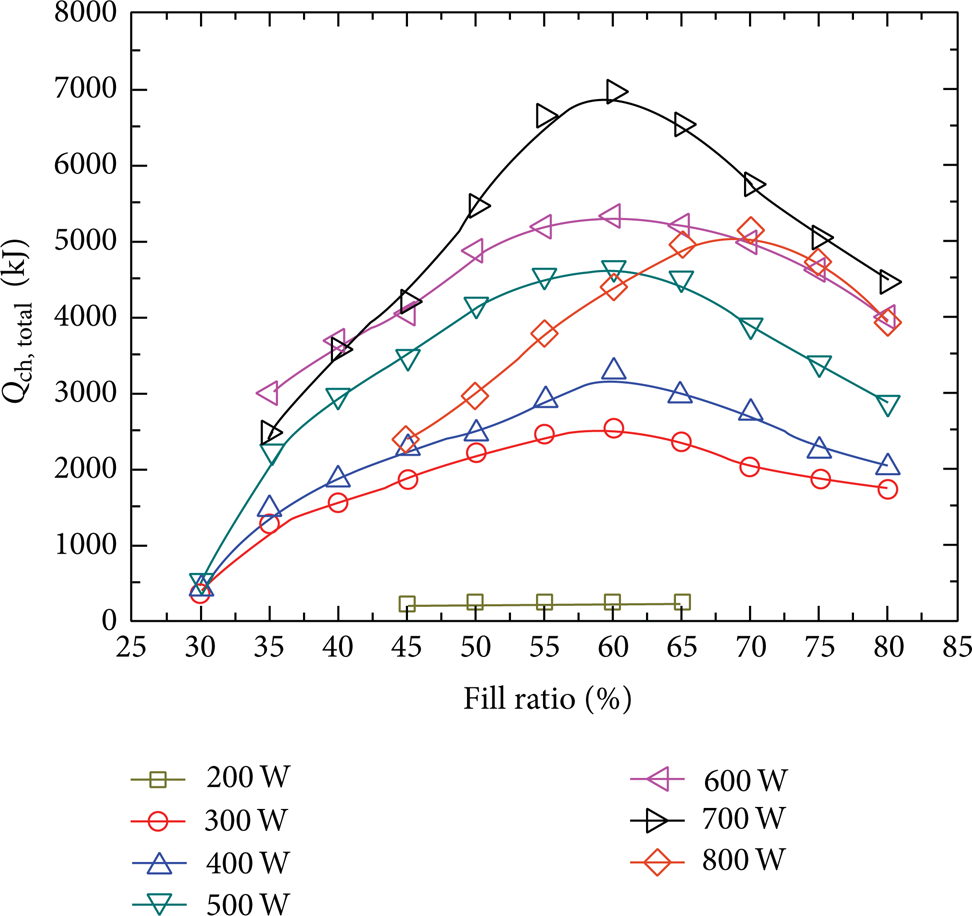
Comparison of stored thermal energy with different fill ratios and heat loads.
The heat charge mode of the ECTS operates based on temperature variations in the storage chamber. When condenser temperatures are higher than MNF temperatures, the ECTS underwent heat charge. Subsequently, the vapor flow in the condenser loop became liquid flow. The loop heat pipe embedded in the storage chamber provides several advantages to thermal storage, such as high heat capacity, a long heat-transfer distance, and operation against gravity. The temperature responses along the condenser loop at 300 W, 500 W, and 700 W are shown in Figure 5(a). After this heat charge, the temperature differences between the ends of the condenser loop were 22.2°C, 26.1°C, and 34.7°C, respectively. However, MNF flow convection was intensified in the storage chamber and it reduced the temperature differences within compartments. Corresponding to Figure 5(a), the variations of compartment temperatures all followed similar trends (Figure 5(b)). Because of the large specific heat capacity of MNF and thermal convection, only small temperature variations were measured throughout the experiment. This further suggests the operational stability of ECTS.

Temperature responses (a) along the ECTS condenser loop and (b) within the storage compartments at the heat load of 300 W, 500 W, and 700 W.
The uniformity of the thermal energy stored in the compartments directly affects the ECTS performance and reliability. The storage efficiency of the ECTS depends on the temperature variations between the condenser loop and the storage chamber. The stored thermal energy for the chamber compartments and their deviations are shown in Figure 6. At 300 W, 2537.22 kJ of thermal energy was measured and stored, and the storage efficiency of the ECTS was as high as 78.31%. In this heating condition, the deviation of stored thermal energy in the compartments, obtained by estimating the relative error, was less than ±0.06. At 500 W, a higher stored result of 4644.36 kJ was obtained, yielding a storage efficiency of 82.73%. The deviation of stored thermal energy within the compartments decreased to a range of less than ±0.04. When the heat load increased to 700 W, a larger amount of thermal energy was released from the condenser loop and stored in the ECTS with a high efficiency of 84.46%. The stored thermal energy was 7041.30 kJ and the deviation within the compartments was less than ±0.05. Although Compartment 1 always absorbed more thermal energy than the other compartments, there were no large temperature variations among the compartments. Thus, this electromagnetic-controlled design prevented thermal stratification and evenly enhanced ECTS efficiency.

Deviation of stored thermal energy in storage compartments at the heat load of 300 W, 500 W, and 700 W.
A further test was also conducted for validating the operational performance of ECTS at a simultaneous heat charge and utilization mode. The starting temperature of thermoelectric module was set as a value of 28°C. Figure 7 depicts temperature variation within the storage chamber during this mode. Same as the time of heat charge, MNF performed well in thermal convection and no thermal stratification can be confirmed. Since the heat charge and heat utilization were conducted at the same instant, temperature distribution of the storage chamber upon the MNF circulation would have a bearing on conversion rate of thermoelectric module. The chamber temperatures increase slowly as the thermoelectric module started. Compared with Figure 5(b), more tiny temperature differences among the compartments can be measured than those at heat charge mode. A mean value of temperature depression finally obtained with heat charge mode for 300 W, 500 W, and 700 W was 8.1°C, 19.2°C, and 25.2°C, respectively. It is seen that the MNF can store excess thermal energy continuously under a low temperature as the heat load was greater than heat supply, thus indicating that the ECTS did have the anticipated function of automatic adjustment in thermal capacity.

Temperature responses within the storage compartments on simultaneous heat storage and utilization at the heat load of 300 W, 500 W, and 700 W.
6. Conclusion
This study successfully proposed an effective EMHD method used in a thermal storage design. MNF, used as a nanoparticle-enhanced LHM, revealed its sensitive features of thermal transportation and electromagnetic induction. It was highly affected by electromagnetic coupled effect and can be induced local flow perturbations, enhancing thermal convection of its own. The ECTS performed well in both heat charge and heat utilization, and it especially achieved an optimum efficiency of 84.46% at 700 W. Accordingly, the research gave more prominence showing the feasibility of semiactive thermal storage with a nanoparticle-enhanced LHM. The ability of MNF to store thermal energy confirmed it as a candidate for novel applications of waste heat recovery technology.
Conflict of Interests
The author declares that there is no conflict of interests regarding the publication of this paper.
Footnotes
Acknowledgment
The author deeply appreciates the financial support provided by the National Science Council (NSC) of Taiwan, under Contract no. NSC 103–2623-E-606-014-D.