
Abstract
Control Arm (CA) of a suspension plays an important role in the automotive ride comfort and handling stability. In this paper, the topology optimization model including ball joints and bushing for topology optimization of an aluminium CA is established, where a ball joint is simplified as rigid elements and the elastic properties of a rubber bushing are estimated using Mooney-Rivlin constitutive law. A method for treating with multiple loads in topology optimization of CA is presented. Inertia relief theory is employed in the FEA model of the CA in order to simulate the large displacement motion characteristics of the CA. A CA is designed based on the topology optimization results, and the strength, natural frequency, and rigidity of the optimized CA are calculated. The calculated results show that the performances of the optimized CA with the proposed model meet the predetermined requirements.
1. Introduction
Control Arm (CA) is an important component of the suspension system for the automotive ride comfort and handling stability. Optimization techniques are used widely in the design of a CA to obtain predetermined performance goals subjected to constraints specified (mass reduction, etc.). Structural optimization can be categorized into three classes: size optimization, shape optimization, and topology optimization. Krishna [1] and Krishna and Anderson [2] use shape optimization in the design stage of an upper CA to reduce weight, bring down stresses, and raise the first frequency. However, solutions obtained by size and shape optimization methods keep the same topology of the initial design. Therefore, these solutions are often far from optimal design because other competing topologies are not used.
Recently, topology optimization technique has been increasingly used in the design of a CA [3–9]. Two topology optimization approaches can be identified in the literature. The first approach (microstructure approach) introduced by Bendsøe and Kikuchi [3] is to find the size and orientation of holes in each element of the finite element analysis (FEA) model. The microstructure approach is based on the assumption of a composite material with the microstructure whose properties are homogenized by a rigorous mathematical procedure [8]. The second approach (density approach) that has become very popular recently is based on the density formulation [4]. In the density approach, the material density in every finite element of the structure is selected as the design variable and the immediate density is penalized during the optimization iterations [8]. Unlike the microstructure approach in which individual elements are considered to be of isotropic material, the density approach only requires one design variable for each finite element.
Demirdogen et al. [5] describe the detailed steps to minimize the weight of an upper CA using topology optimization. D.-C. Lee and J.-I. Lee [6] utilize topology and shape optimization methods in the design stage of an aluminium Control Arm for an automotive suspension. In comparison with a steel Control Arm, the mass reduction is 50 percent and the structural rigidity and strength are improved up to 40 percent. Nelson [7] describes a practical application of the die draw direction constraints in topology optimization and shows how they are effectively used to improve the design of an automotive lower CA. Yang et al. [8] present and discuss new applications of topology optimization including weight reduction, manufacturing process selection, weld, and bead pattern designs for some three-dimensional automotive components.
However, in the above literature, the effects of ball joints and bushings on the performances of a CA are not considered and only taken them as fixed constraints in the FEA model of the CA. Hope et al. [9] simulate elastic characteristics of the bushing in three translational directions using three springs. However, the elastic characteristics of the bushing in the three rotational directions are not simulated.
In this paper, topology optimization is performed based on the density approach and a topology optimization design flow of the CA is established. Enhancements of the method proposed in the paper are (1) in the FEA model of CA, ball joints and bushings are included, and the ball joint is simplified as rigid elements and the elastic properties of a rubber bushing are modeled using Mooney-Rivlin constitutive law; (2) the method for treating multiple loads in topology optimization of CA is presented.
Since the CA may have large displacement motion due to the characteristics of the ball joints and rubber bushings, thus inertia relief theory is considered in the topology optimization. The CA is designed based on the topology optimization methods proposed in this paper, and the strength, natural frequency, and rigidity of the optimized CA are calculated. The calculated results show that the performances of the optimized CA meet all the predetermined requirements. In comparison with the traditional CA model without consideration of the functionality of the ball joints and bushings, it is concluded that the proposed CA model can more actually describe the operating characteristics of the CA.
2. Procedures of Topology Optimization for Control Arms
The position of the Control Arm (CA) and its design space are shown in Figures 1(a) and 1(b), respectively. The outside and inside ends of the CA are connected with the hub using the outside ball joint and the body using the inside ball joint plus the rubber bushing, respectively. For the inside ball joint, the ball seat is embedded into the housing of the CA body; for the outside ball joint, the ball seat is forged together with the CA body. And the assembly method of the inner metal tube of the rubber bushing and the CA body is tight fit; thus there is no relative displacement between them. The topology optimization flow chart used by the authors is given in Figure 2.

Position of a CA and its initial configuration.
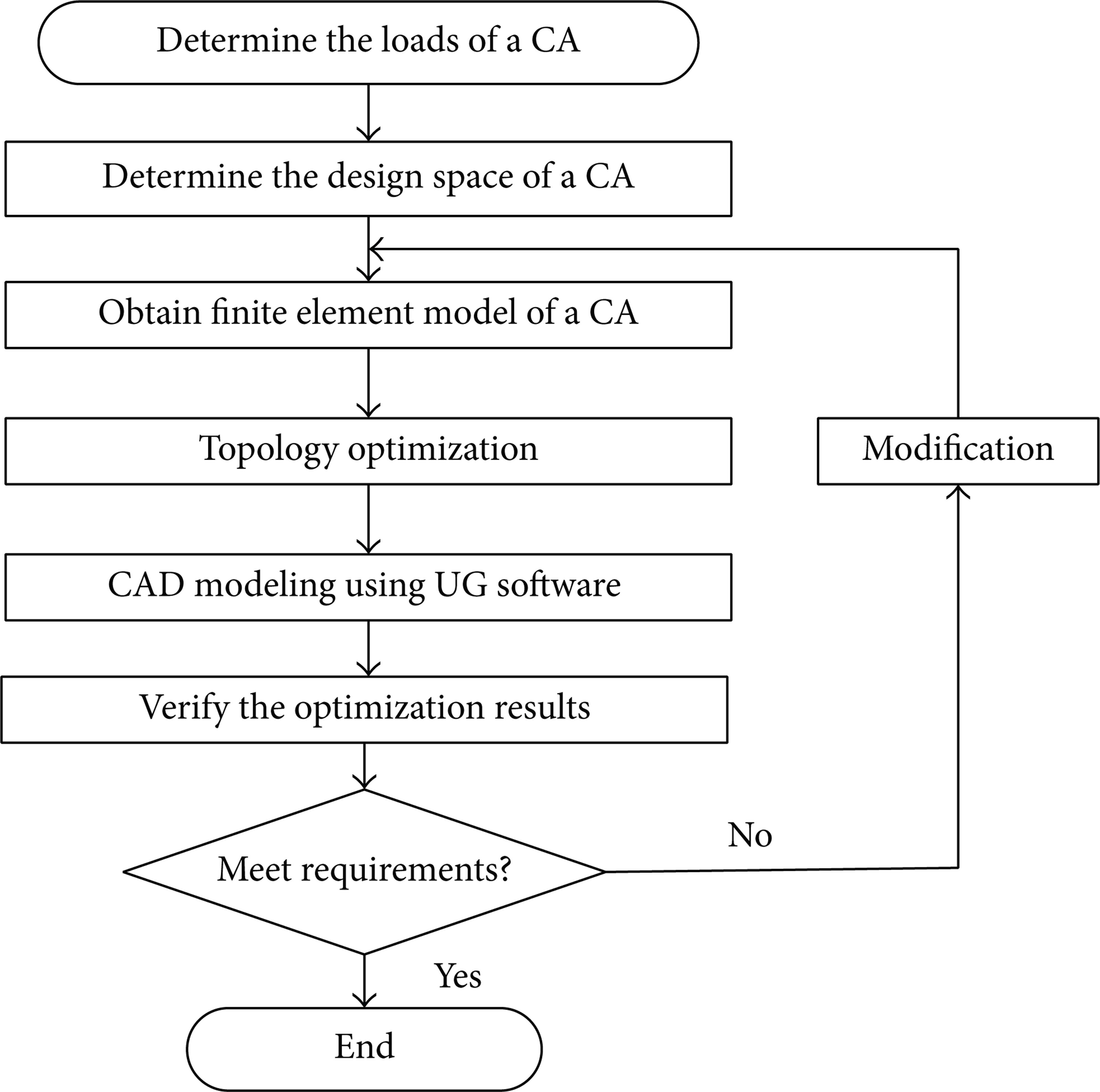
Topology optimization flow chart of the CA.
3. Modeling of Control Arms for Topology Optimization
3.1. Modeling of the Ball Joints
In this section, the dimension design and performance evaluation of the two ball joints are discussed. The configurations of typical ball joint assemblies are shown in Figure 3. A ball joint assembly is assembled with the CA body with the ball seat through the assembly methods of forging, embedding, jointing, bolting, and rivet joint, and so forth. Performance of a ball joint includes the radial and axial stiffness of the ball head, the starting and operating torque of the ball head, the drawing strength, pressing strength, and so forth. The geometries of the two ball joints are shown in Figure 4.
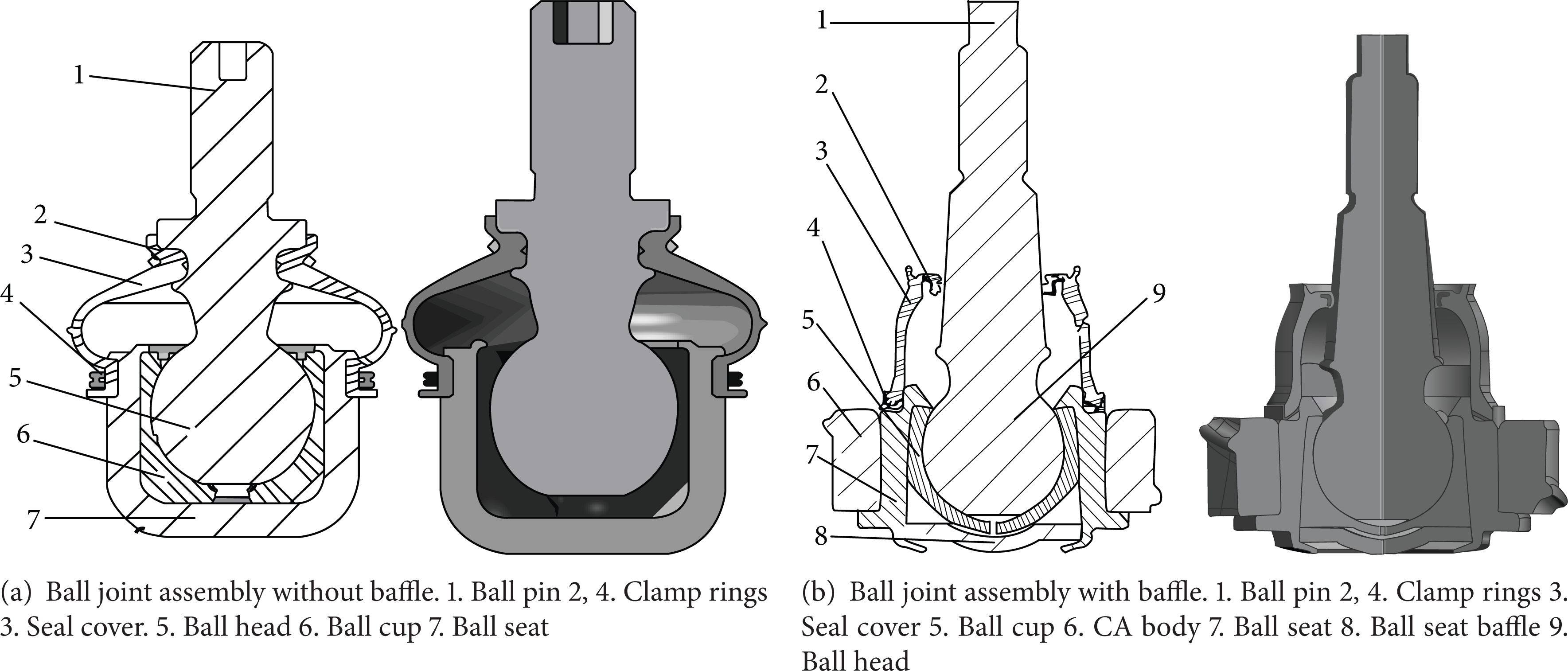
Configuration of typical ball joint assemblies.
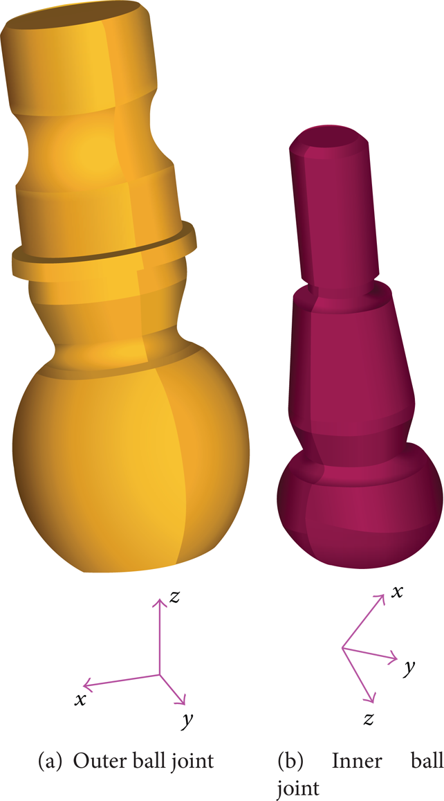
Geometries of the two ball joints.
Assume that the ball head is made of aluminium. The surface of the ball head is fixed and the upper face of the ball pin is the loading face. The two ball joints are meshed with 10-node tetrahedron elements and Figure 5 shows the FEA model of the two ball joints. The comparison of the required and the calculated static stiffness of the two ball heads is shown in Table 1. It is seen that the initially designed ball joints meet the stiffness requirements.
Static stiffness of the ball heads (N/mm).

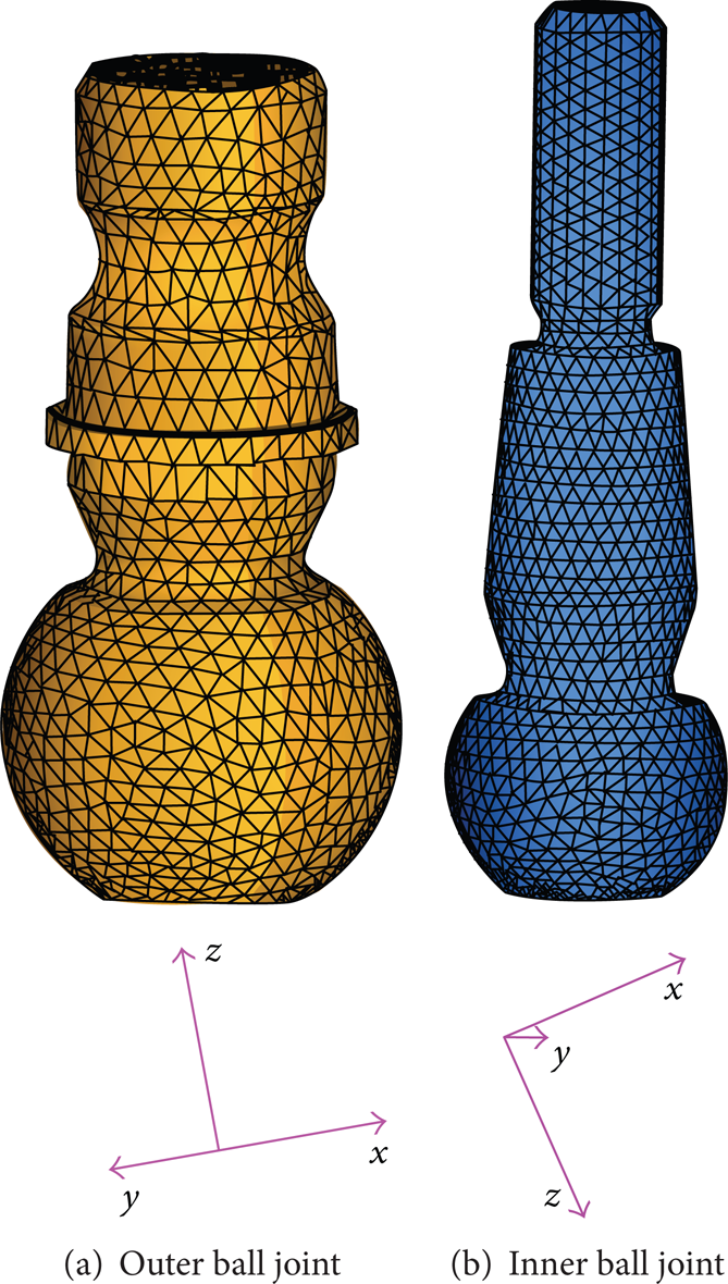
FEA models of the two ball joints.
Figure 6 shows the photos of the two designed ball joins.

Two designed ball joints.
3.2. Modeling of the Rubber Bushing
In this research, the radial stiffness and the axial torsion stiffness of the rubber bushing for the Control Arm are required to be larger than 630 N/mm and 1.35 N·m/deg, respectively. A regular rubber bushing can be used here according to design experience, and the general configuration is shown in Figure 7. A rubber bushing is assembled with the CA body through the outer or inner metal tubes, and the assembly methods include tight fit, jointing, and adding lock ring.

Configuration of the regular cylinder rubber bushing.
The static stiffness of the regular rubber bushing can be calculated by experiential formula [10] and FEA method. The experiential formula of the radial stiffness of the rubber bushing can be expressed by [10]

where k l is the form factor, G is the shear elastic modulus, and the relation between G and Shore hardness Hs can be written as
The dimension ratio, η, is defined as

The relation between k l and η can be described using the curve shown in Figure 8.

Form factor of the rubber bushing under radial loading.
Under the assumption of plane strain, the axial stiffness and the axial torsion stiffness of the regular cylinder rubber bushing can be expressed by the following [10]:


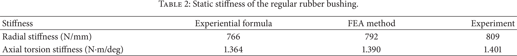
The initial dimensions of the regular rubber bushing are D = 60 mm, d = 30 mm, and L = 30 mm. The Shore hardness of the rubber material is 50 and the Mooney-Rivlin constitutive law is employed in the FEA of the static stiffness of the rubber bushing. Table 2 shows the radial stiffness and axial torsion stiffness of the rubber bushing obtained by using the experiential formula, FEA method, and experiment. It can be seen that the errors of the experiential formula are larger than that of the FEA method, thus for the rubber bushing with complicated geometry, the FEA method is preferred. It can be seen that the stiffness of the bushing in the two directions meet the predefined requirements. Therefore, the designed regular rubber bushing can be used in the FEA model of the CA.
Static stiffness of the regular rubber bushing.
3.3. Determine the Loads and Design Space of the CA
Forces at the outer ball joint of the CA for 16 typical load cases can be tested or calculated using the methods proposed by the author of this paper [11]. Table 3 shows the 16 typical load cases and the calculated forces at the outer ball joint of the CA, where g is the gravity acceleration.
Sixteen typical load cases and the forces at the outer ball joint of the CA.

Six worst conditions shown in Table 4 are selected from the 16 loads cases and are used for the topology optimization of the CA.
Six load cases used in the topology optimization of the CA.

The six worst conditions presented in Table 4 are selected if the force at one direction is at maximum or at minimum, and they are the most dangerous cases to damage the Control Arm.
According to the operating range of the CA, the design space is the region except for the ball joints and the rubber bushing as shown in Figure 9.
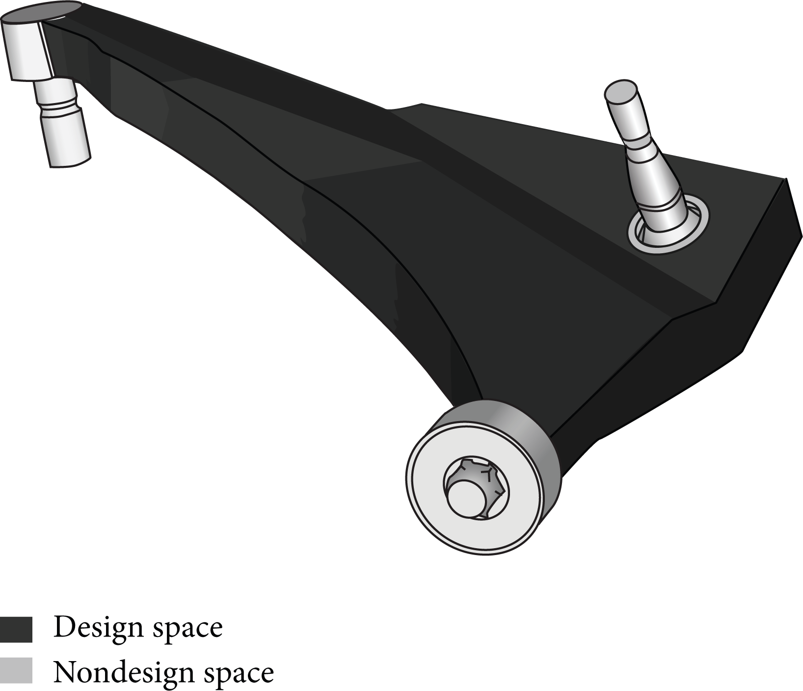
Design space of the CA.
3.4. Modeling of a Control Arm
For simplicity, CA I and CA II are defined as the models modeled with the presented and traditional methods, respectively. For CA I, the rubber bushing is meshed with 10-node tetrahedron elements as shown in Figure 10, and the nodes at the inner tube coincide with those of the CA. Three rigid bar elements are used to simulate the motion of the inner ball joint as shown in Figure 11. Three translational degrees at two ends of elements 1 and 2 are fixed, and each end of element 3 has six degrees of freedom. The elastic properties of the rubber bushing are estimated using Mooney-Rivlin constitutive law.
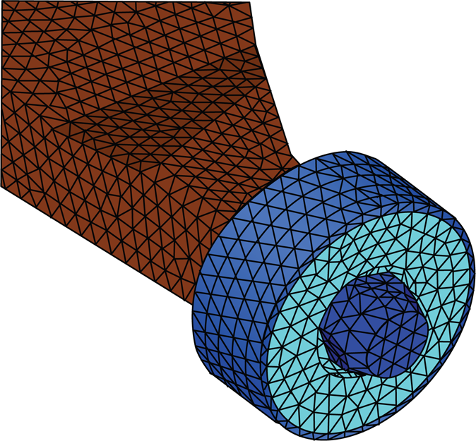
FEA model of the rubber bushing.
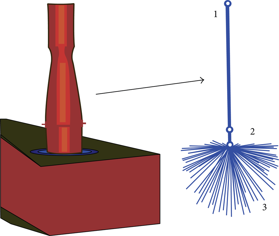
Simplified FEA model of the inner ball joint.
The material of the CA and the ball joint is 6061A-T6. The FEA model of the CA is shown in Figure 12(a). For comparison, the traditional FEA model of a CA is given in Figure 12(b).

Comparison of the presented and traditional FEA models of the CA.
For CA II, the rubber bushing and the inner ball joint are considered to be rigid bodies. One constraint position is at the center of mass of the inner ball head and the three translational degrees of freedom are fixed. Another constraint position is at the inner ball pin and also the three translational degrees of freedom are fixed. And the loading position of CA II is at the center of mass of the outer ball head.
For CA I, the rubber bushing and the inner ball joint are the ones designed in Sections 3.1 and 3.2. The deformation characteristics of the rubber bushing and the rotational characteristics of the ball joints will induce large displacement of the CA. Therefore, the inertial force of the CA should be considered in the FEA model by using the inertial relief theory when the boundary condition is established. The loading position of CA I is at the outer ball pin and the reference point is the center of mass of the CA.
In the following, optimization results of CA I are compared with that of CA II to demonstrate the effectiveness of the method proposed in this research.
3.5. Topology Optimization Method of a Control Arm under Multiple Loads
In order to bear maximum external loads for a Control Arm (CA), the objective of the optimization is to maximize the CA stiffness or to minimize CA compliance. The constraints include limitation of the CA's volume. The stresses of the CA under different loads are not included in the optimization model since it will make the feasible space of the design variable varied suddenly.
Based on the SIMP model [12] and the linear weighting method, the topology optimization model of the CA under multiple loads is expressed as
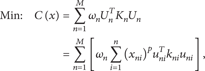

where C(x) in (6a) is the compliance; K n is the global stiffness matrix under load case n; M is the number load cases; p is penalty factor; x ni is the design variable under load case n and its physical meaning is the relative density of element i; u ni and k ni are the displacement vector and the stiffness matrix of element i under load case n, respectively.
The U n and F n in (6b) are displacement vector and external force vector; V(x) and V0 are the limited material volume after optimization and the material volume in design space, respectively; f is the volume fraction.
The ω n in (6a) is the weighting factor under load case n, and the sum of the ω n is equal to 1. In the topology optimization of the CA, how to determinate ω n is very important.
If only one load is applied to the CA, (6a) and (6b) are simplified as


The x = {x1,x2,…,x i ,…,x N } T in (7a) and (7b) is the design variable vector; N is the number of elements.
The procedure for getting ω n (n = 1, 2, …,M) in our study is as follows. Firstly, one can get the optimum value for compliance, C n (x), and design variables, x n (n = 1, 2, …,M), by optimization of (7a) and (7b) under different load cases of M.
Then by defining C j n = C j (x n ), j = 1, 2, …,M, and by assuming

The total number of (8) is (M + 1). The total number of unknown variables in (8) is also equal to (M + 1). So one can estimate ω1,…,ω M using (8).
4. Results of Topology Optimization of the CA
The topology optimization based on density approach is utilized on the CA with an objective to minimize the part compliance subject to a volume fraction constraint, that is, volume fraction ≤ 0.35. Assume that the lower and upper limits of the relative density are 0.001 and 1.0, respectively, and the penalty factor p = 3 for the SIMP density function [12].
One of the major problems in topology optimization is the manufacturability of the optimization result. The transfer of the topology optimization result into a practical design needs lots of manual interference, such as geometry recovery or shape optimization to obtain further improvement [13]. Therefore, the topology optimization should include manufacturing consideration in order to reduce the loss of performance of the design compared to the optimization result. In this research, a draw direction constraint is employed with the draw direction defined perpendicular to the major plane of the part as shown in Figure 13. The theoretical background of die draw direction constraints in topology optimization is presented in the literature [14, 15]. The use of draw direction constraints simplifies the process of translating the topology optimization result directly into a manufacturability design [13].

Draw direction of the CA.
The topology optimization results of CA I and CA II are shown in Figures 14(a) and 14(b), respectively. For CA I, the relative motion between the CA body and the ball joints are simulated which can avoid local strength deficiency or redundancy around the connection region. The rubber bushing in CA I is modeled using Mooney-Rivlin constitutive model, and the bushing can absorb the torque of the CA through the deformation of the bushing. Thus, it is seen from Figure 15 that the domain between the two ball joints is narrower than that of CA II which can avoid stress redundancy in this region. It can be seen that the optimization results of CA I are more practical than that of CA II because the motion characteristics of the ball joints and rubber bushing are considered in CA I.
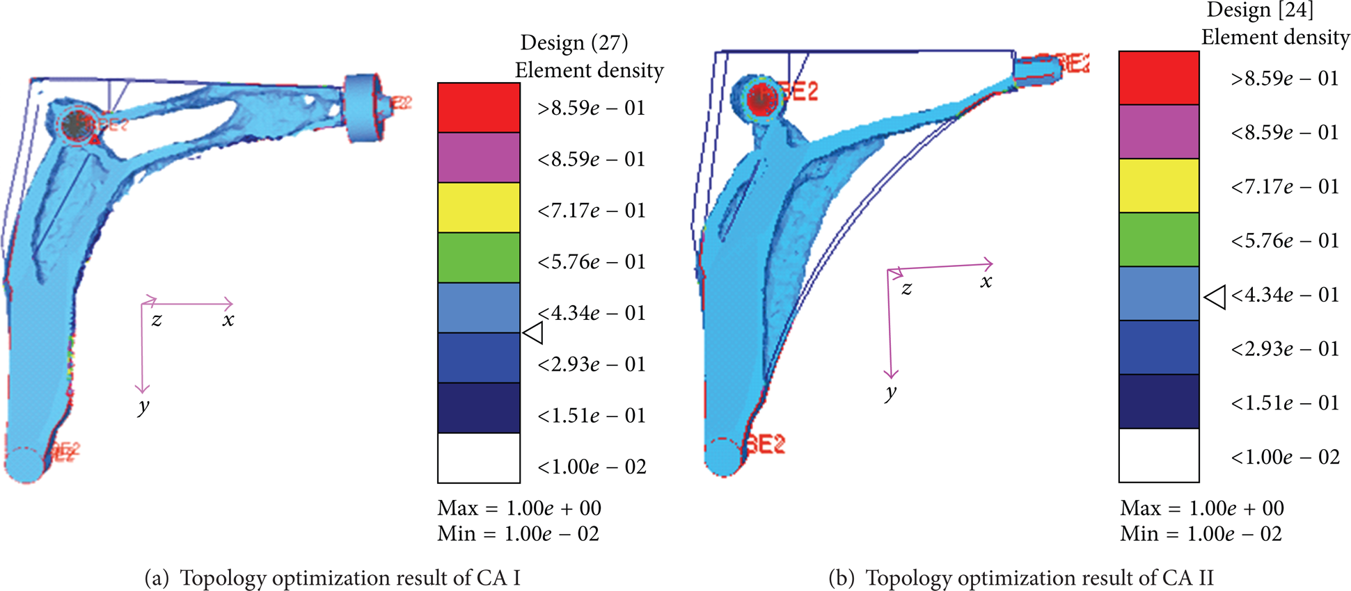
Topology optimization result of CA I and CA II.

Geometries of the optimized CA I and CA II.
5. Verification of the Topology Optimization Results
Figure 16 shows the geometries of the optimized CA I and CA II created by using UG software with considerations of technical and design experience. FEA method is used to verify the topology optimization results of the CA, and the FEA models of the optimized CA are shown in Figure 16.
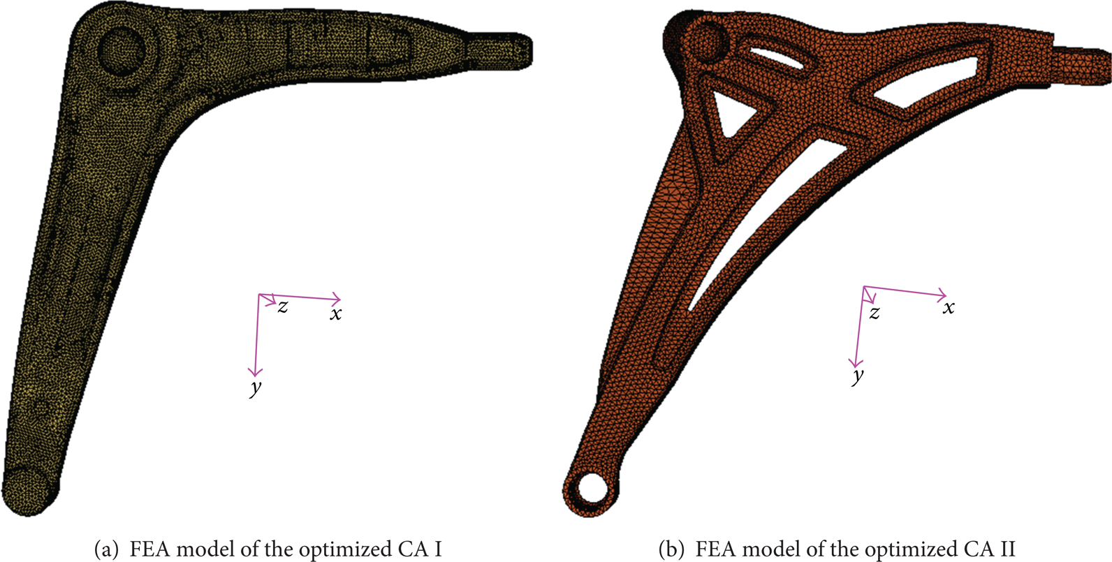
FEA models of the optimized CA I and CA II.
To verify the optimization results, performance calculations of the CA including strength, rigidity, and natural frequencies are given in the following.
5.1. Strength Verification of the Optimized CA
For the six load conditions given in Table 4, the calculated maximum Von Mises stresses of the optimized CA I and CA II are shown in Table 5. Note that the yielding stress of material 6061A-T6 is 275 MPa.
Maximum Von Mises stress (MPa).

From Table 5, it can be seen that for CA II the maximum Von Mises stresses are larger than 275 MPa under load cases of pothole braking, kerb strike II, and reverse vibration damping, while the maximum Von Mises stresses of CA I are smaller than 275 MPa. For static analysis of CA I, the maximum Von Mises stress is larger than 275 MPa due to the fact that the rubber bushing is simplified as fixed boundary condition and thus the inertia of the CA is ignored, which leads to the distortion of the calculated stress. Therefore, the optimized CA I satisfies the predefined strength requirements.
5.2. Rigidity Verification of the Optimized CA
For the safety of the automotive safety, the rigidities of the CA in X- and Y-directions should be larger than 2 KN and 15 KN, respectively. To calculate the rigidities of the CA, the ball joints and rubber bushing need to be ignored, that is to say they can be simplified as fixed boundary conditions. Table 6 shows the required and calculated rigidities of the optimized CA I and CA II in X- and Y-directions. It can be seen that the calculated rigidities of the optimized CA I meet the required values.
Comparison of required and calculated rigidities of the optimized CA (KN/mm).

5.3. Modal Analysis of the Optimized CA
It is known that the natural frequencies of the CA have great impact on the vibration characteristics of the suspension. Generally, the first-order free and constrained frequencies of a CA are required to be larger than 800 Hz and 350 Hz, respectively. The constrained frequencies of a CA are related to the stiffness of the rubber bushing. The calculated natural frequencies of the optimized CA I and CA II are presented in Table 7.
Natural frequencies of the optimized CA (Hz).
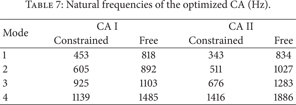
It is seen from Table 7 that the first-order constrained frequency of CA II is smaller than 350 Hz, while the first-order free and constrained frequencies of CA I meet the specifications.
6. Conclusions and Discussions
This paper presents a procedure for the topology optimization design of the CA in the automotive suspension system. The main contribution of this paper is the establishment of the topology optimization model for the CA with considerations of the elastics of ball joints and rubber bushings, and the method for treating with multiple loads in topology optimization of CA. The topology optimization results are compared with and without the modeling the stiffness of ball joints and rubber bushings. It is concluded that the elastics of ball joints and bushings should be modeled in the topology optimization of a Control Arm in order to meet the requirements of stress, stiffness, and first-order natural frequency for the Control Arm. The proposed modeling method can also be applied to structural topology optimization of other automotive structures or components containing ball joints or rubber bushings.
The limitation of this paper is that only a draw direction constraint is employed to simplify the requirement for manufacture.
Conflict of Interests
The authors declare that there is no conflict of interests regarding the publication of this paper.
Footnotes
Acknowledgments
The author gratefully acknowledges the financial support of International Advanced Forestry Science and Technology project (no. 2011-4-02), the Fundamental Research Funds for the Central Universities (no. YX201303), and New Faculty Support Foundation of Beijing Forestry University (no. 2010BLX11).