
Abstract
The operation principle of an electromagnetic harmonic drive is analyzed and its speed ratio equation is given. The equations of the displacements of the flexible ring under magnetic forces and the equations of the output torque between the flexible ring and rigid one are deduced. Using these equations, the displacement distribution of the flexible ring is investigated, and the effects of the system parameters on output torque are discussed. The results show that the current intensity of the coils, the airgap, the iron core length, and the position of the rigid ring have effects on the output torque for the drive system. The current intensity can be taken as the main control parameter of the output torque.
1. Introduction
The electromagnetic harmonic drive was proposed by Herdeg [1]. It can transmit large torque in a small size and is suitable for the technical fields such as aviation and space flight. Besides the above-mentioned fields that require compactness, the drive can be used in fields such as robots that require accurate control. Some countries have been developing the harmonic drives for years [2–4]. Ostapski and Mukha analyzed the stress state in the flexspline with a variable curvature as well as bearings of the generator by FEM [5]. Dhaouadi and Ghorbel proposed a mathematical model and its parameter identification scheme for harmonic drive gears with compliance and hysteresis to represent the torque-displacement relationship across the flexspline of the drive [6]. Dong et al. presented the geometry-relevant operation of harmonic drives under an ideal little or no-load condition and demonstrated how the cup affects tooth conjugation and the conjugate tooth profiles [7]. Vassileva et al. developed a friction model to control the sensorless torque of the harmonic drive [8]. Folega investigated the dynamic properties of some structural components of harmonic drive by FEM [9]. Tjahjowidodo et al. proposed a model for torsional compliance and analyzed the nonlinear torsional behaviour in harmonic drives [10]. Lu et al. presented a scheme for controlling the output torque of a harmonic drive equipped with a torque sensor [11]. Hei and Zhou presented a modeling method of harmonic drive system with low-frequency resonance and predicted the resonant frequency and dynamic performance of the drive system [12]. Chen et al. investigated the internal forces and the deformation of the neutral line of flexspline for the harmonic drive [13].
In a word, a number of studies about the harmonic drives were done. The harmonic drives can be classified into four types. They are mechanical harmonic gear drive, electromagnetic harmonic drive, harmonic piezodrive, and harmonic electrostatic drive [14, 15]. Compared with the mechanical harmonic drive, electromagnetic harmonic drive has a small size. Compared with the harmonic piezodrive and harmonic electrostatic drive, electromagnetic harmonic drive has a large output torque.
For the electromagnetic harmonic drives, Janes proposed a type of the electromagnetic force change to avoid eddy current through the metal flexible ring [16]. Software was used to realize the controlling of high performance servo driving system for magnetic type harmonic gear drive [17]. Rens et al. investigated a novel magnetic harmonic gear drive which has high reliability and inherent overload protection while having a high efficiency [18]. Another new electromagnetic harmonic drive was investigated in which oscillating teeth transmission principle was used [19]. Liu et al. established an analytical model of the eccentric magnetic harmonic gear based on the boundary perturbation method and calculated the eccentric airgap magnetic field [20]. Uchimura and Saito proposed a control method of the harmonic magnetic gear to attenuate adverse effects due to cogging torque on the vibratory system [21].
The electromagnetic harmonic drive consists of six basic elements as shown in Figure 1: (a) the bearing block, 1; (b) the flexible ring, 2; (c) the housing, 3; (d) the coils, 4; (e) the rigid ring, 5; and (f) the axis, 6, which is the output shaft upon which the flexible ring is mounted. The flexible ring is made with ferromagnetic material. The coils and the rigid ring are fixed on the housing. The coils are energized sequentially by voltages, and the resulting rotational electromagnetic field causes periodic elastic deformation of the flexible ring. This deformation is accompanied by periodic contact between the flexible ring and rigid ring. It causes the normal pressure and the relative slip between the flexible ring and rigid ring. So, the friction force occurs between them. As the rigid ring is fixed, the friction force drives the flexible ring to rotate.
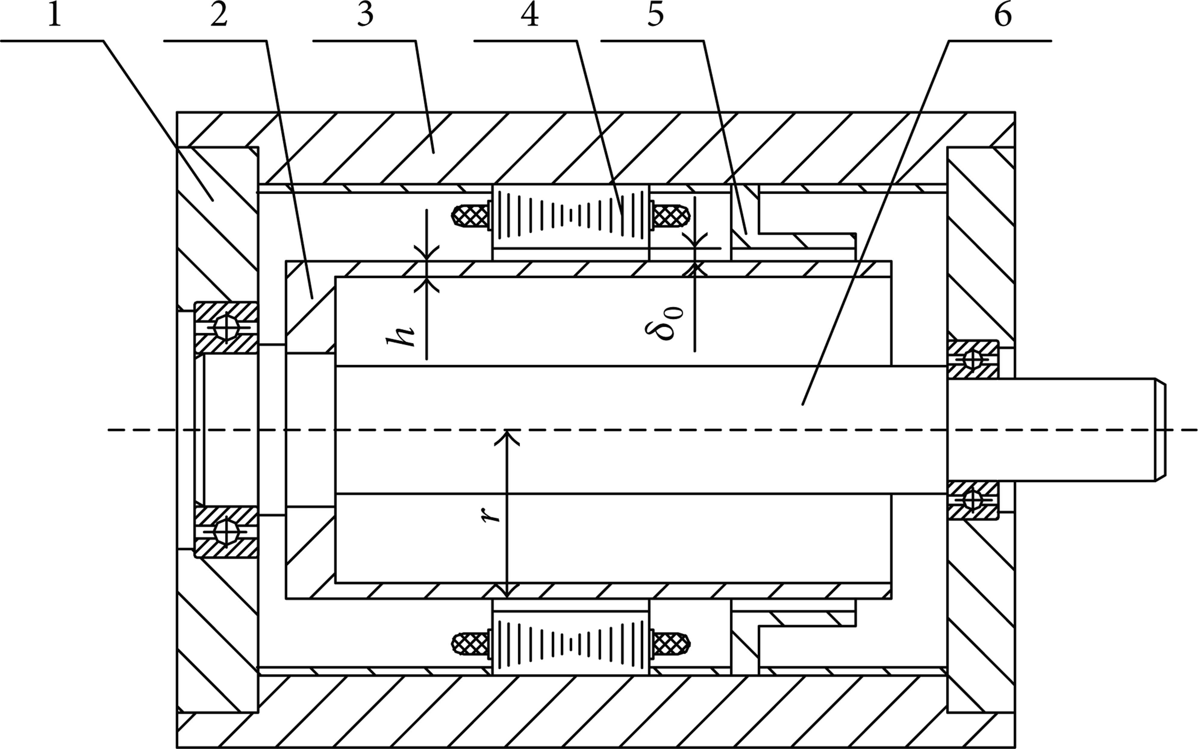
The electromagnetic harmonic drive, 1: bearing block, 2: flexible ring, 3: housing, 4: coils, 5: rigid ring, and 6: axis.
Figure 2 shows the operation of an electromagnetic harmonic drive with single phase and single pole pair rotary electromagnetic field. Initially, a voltage is applied to the coils 1 (South Pole) and another to coils 4 (North Pole), thereby causing an elastic deformation of the flexible ring. This deformation is shown in Figure 2(a). Next, a voltage is applied to the coils 2 (North Pole) and another to coils 5 (South Pole), causing the elastic deformation of the flexible ring shown in Figure 2(b). Voltages are then similarly applied sequentially to coils 3 and 6 (Figure 2(c)), 4 and 1 (Figure 2(d)), 5 and 2 (Figure 2(e)), and finally 6 and 3 (Figure 2(f)). This sequential energization completes one electrical cycle. Note that the position of the black dot shown in Figure 2(f) has rotated slightly after one complete electrical cycle compared to its initial position in Figure 2(a). Note also that the flexible ring rotates in the opposite direction to the electromagnetic excitation sequence, shown by the arrow in Figure 2.

Operation of the electromagnetic harmonic drive.
The output torque of the electromagnetic harmonic drive is the main performance parameter of the electromagnetic harmonic drives which has not been investigated in detail yet.
In this study, the speed ratio equation of the electromagnetic harmonic drive is given. The equations of the displacements of the flexible ring under magnetic forces are deduced. The magnetic torque, friction torque, and output torque between the flexible ring and rigid one are proposed. Using these equations, the displacement distribution of the flexible ring is investigated, and the output torque and the effects of the system parameters on it are discussed. A lot of useful results are obtained. The results can be used to design and manufacture the drive system.
2. Calculating Methods
2.1. Speed Ratio
For simplifying analysis, the radial displacement u of the flexible ring under electromagnetic force can be expressed as

where umax is the maximum radial displacement of the flexible ring and φ is the position angle on the flexible ring.
The micro ring is considered to be inextensional ring, so the normal strain of the ring equals zero (∂v/∂φ = − u). Thus, the circumferential displacement v of the micro ring can be given as

As the electromagnetic field is rotating, the displacements of the micro ring are variable as well. The traveling wave in the flexible ring is given by following equations:

where ω is rotating speed of the electromagnetic field and t is the time.
The radial speed v r of the traveling wave is
The tangential speed v t of the traveling wave is

As the flexible ring contacts with the rigid ring, the tangential speed of the traveling wave at contact point between them decides the rotating speed of the flexible ring. The tangential speed is

The direction of the tangential speed is identical to the direction of the rotating electromagnetic field. As the rigid ring is fixed, the rotating direction of the flexible ring is opposite to the direction of its traveling wave movement. Thus, the rotating speed v f of the flexible ring is

where r s is inside radius of the rigid ring.
If the speed ratio i of the drive is defined as the ratio of the electromagnetic field rotation speed to the flexible ring rotation speed, it can be expressed in terms of the geometrical parameters of the drive as

where umax = r s − r f and r f is outside radius of the flexible ring. Substituting the equation umax = r s − r f into (8) yields
where minus means that the flexible ring rotates in the opposite direction to the electric field rotation.
2.2. Electromagnetic Force and Displacements of the Flexible Ring
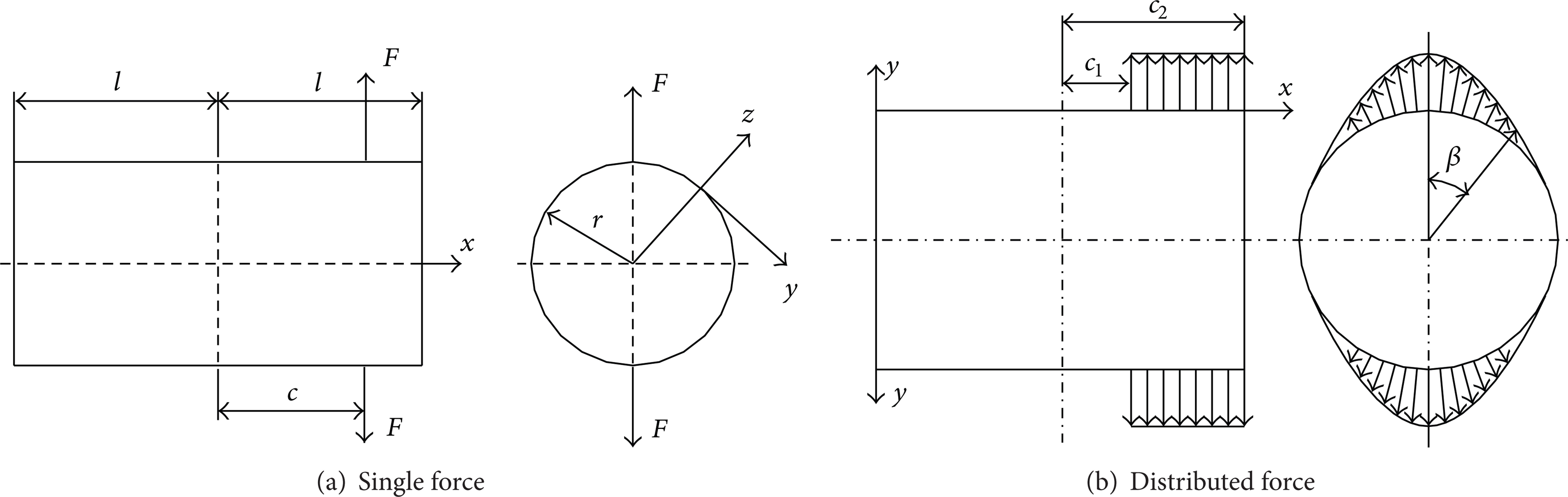
The flexible ring under the load is shown in Figure 3. Figure 3(a) shows the flexible ring under the single force, and Figure 3(b) gives one under the distributed force. In Figure 3(a), F denotes the single force, c is the position of the force F, l is the half of the imaginary length of the flexible ring, r denotes the radius of the flexible ring, and x, y, and z are the coordinates on the flexible ring. Under the single force, the displacements of the flexible ring can be given as

where u, v, and w are the axial, tangent, and radial displacements of the flexible ring, respectively. θ is the central angle between the displacement point and force F point. K is the bending stiffness of the flexible ring, K = Eh3/12(1 − γ). Here, E is the modulus of elasticity of the ring material and γ is the Poisson's ratio. h is the thickness of the flexible ring.
Flexible ring under the load.
In the electromagnetic field, the distributed electromagnetic force occurs on the flexible ring (see Figure 3(b)). From (10), the displacements of the flexible ring under the distributed electromagnetic force can be given as

where c1 and c2 are the initial point and the end point of the electromagnetic force in the x direction, respectively. F(β, c) is the distributed electromagnetic force as the function of the position coordinates β and c.
When a 3-phase source is connected to the coils, a rotating electromagnetic field is formed. The magnetic induction intensity caused by the airgap magnetic potential as the function of the position coordinates β and the time t can be given as

where Bδ = μ0F1/δ0 is the amplitude of the magnetic flux density in the airgap, δ0 is the initial airgap thickness, d m is the maximum radial displacement of the flexible ring, μ0 is the magnetic conductivity of free space, μ0 = 4π × 10− 7 W/m·A, and F1 is the amplitude of the three-phase composite first-harmonic magnetic motive force.
From (12), one can obtain the radial electromagnetic force per unit area on the flexible ring

where P1 = Bδ2/2μ0.
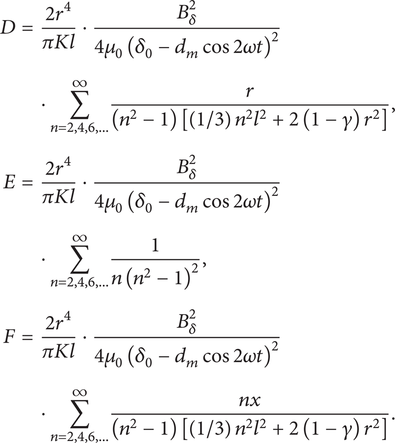
Substituting (13) into (11), the displacements of the flexible ring under the distributed electromagnetic force can be given as
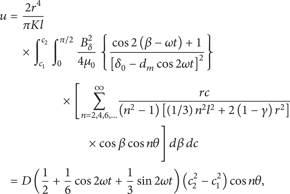
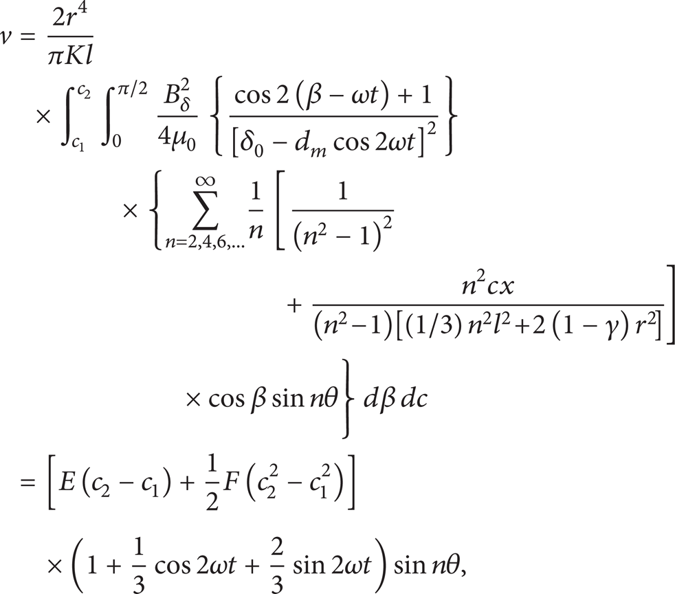
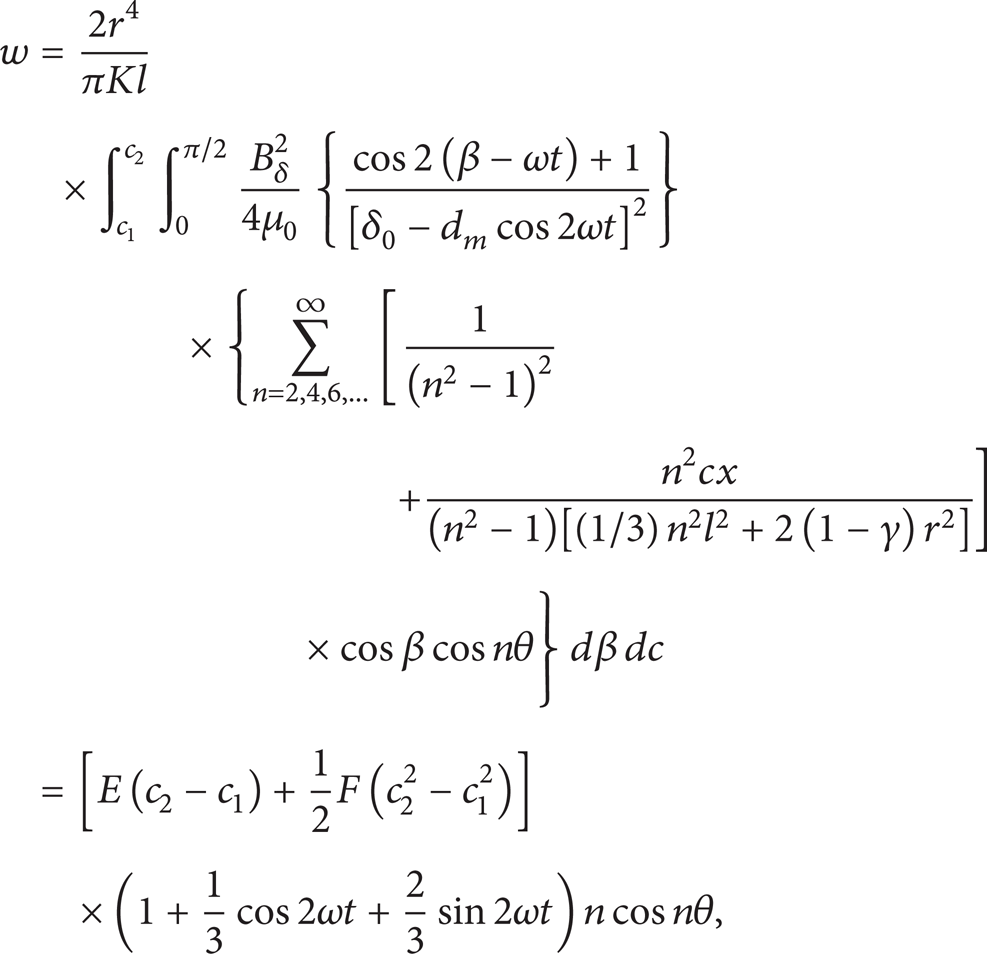
where
At the static state (t = 0), the displacements of the flexible ring under the distributed electromagnetic force can be changed into following form:


where

2.3. Magnetic Torque
When the magnetic field rotates by angle θ, the magnetic torque between the flexible ring and the rigid one can be given as
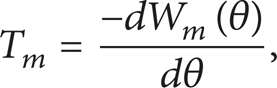
where W m is magnetic energy change between the flexible ring and the rigid one.
When the magnetic field rotates by angle θ, the magnetic energy change between the flexible ring and the rigid is equal to the magnetic energy intensity b multiplied by the volume change of the airgap

where

Flexible ring after rotating angle θ.
Letting w1 and w2 denote the average radial displacements of the flexible ring at the angle ranges (− β, − β + θ) and (β, β + θ), respectively, the average airgaps δ1 and δ2 can be written as δ1 = δ0 − w1 and δ2 = δ0 − w2. Thus, (19) can be changed into the following form:

The average magnetic flux intensity

From (14c), the average radial displacements w1 and w2 can be given by


Substituting (21)–(23) into (20) yields

Substituting (24) into (18) yields

where

From c1 to c2, the average value of the maximum radial displacement (at ϕ = 0) is

Letting d m = w max 0, and substituting it into (27), d m can be determined. d m is substituted into (25) and the magnetic torque between the flexible ring and the rigid one can be determined.
2.4. Friction Torque
The contacting radial deformation w r between the flexible ring and the rigid one can be written as

where δ′ is the clearance between the flexible ring and rigid one.
At the point p (see Figure 5), the radial contacting deformation is

where F r is the contacting force between flexible ring and rigid one and c* is the position coordinate of the rigid ring center.

Contacting force between the flexible ring and rigid one.
From (29), one knows

Letting the contacting force distribution per unit area between the flexible ring and rigid one be

where l′ is the width of the rigid ring.
From (31), one knows

The friction torque between the flexible ring and rigid one is

where μ is the friction coefficient and R is the radius of the rigid ring.
2.5. Output Torque
The output torque of the drive system is equal to the friction torque minus the magnetic torque. So, the output torque can be written as

Substituting (33) and (25) into (34) yields
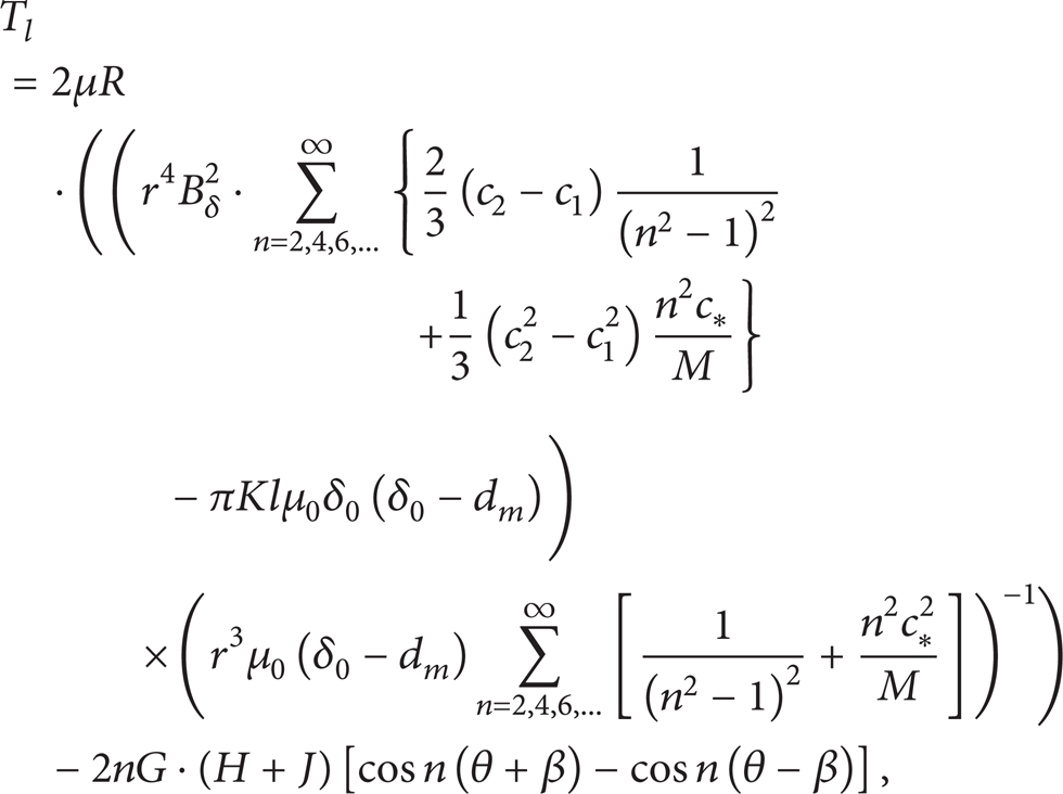
where

3. Results and Discussion
At static state (t = 0), the electromagnetic force between the rigid ring and the flexible ring changes with the point position on the flexible ring and the airgap thickness (see Figure 6). From Figure 6, one knows that the electromagnetic force between the rigid ring and the flexible ring is the maximum at β = 0 and it is zero at β = π/2. From β = 0 to β = π/2, the electromagnetic force reduces gradually. For the same angle β, the electromagnetic force grows significantly with decreasing the airgap thickness δ0. For favoring machining, the airgap thickness should not be taken too small. So, the airgap thickness is taken as δ0 = 0.5 mm.
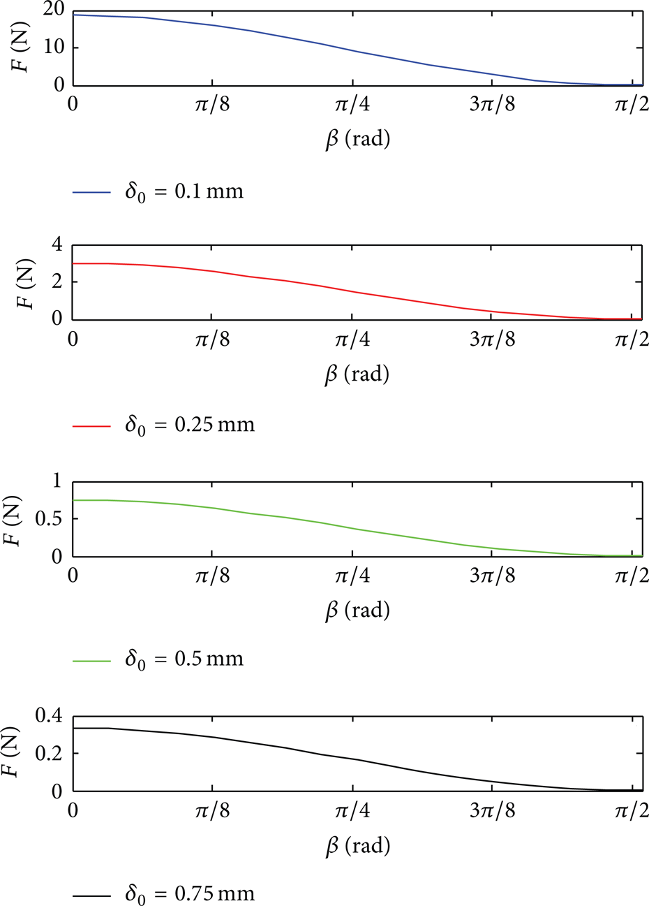
Changes of the electromagnetic force F with β for different δ0.
The flexible ring is a cup shell. The position of its cup bottom can be determined as below. At the cup bottom, the radial and tangent displacements of the flexible ring are equal to zero; that is, w = 0 and v = 0. From (10), one knows that the position of the cup bottom is (see Figure 7)


The position of the flexible ring cup bottom.
From the equation, the position of the cup bottom can be calculated (x0 = − 16.14 mm). The position parameter and other parameters of the drive system are given in Table 1.
System parameters.

Substituting the parameter values in Table 1 into equations in the paper, the displacements u, v, and w changes of the flexible ring along with the time in operation are investigated (see Figure 8). Here, the rotating frequency of the magnetic field is 50 Hz. Figure 8 gives changes of the axial, tangent, and radial displacements of the flexible ring at the section C2 along the time and the angle position. Figure 9 gives distribution of the radial displacements of the flexible ring at t = 0. Figures 8 and 9 show the following.

Displacement changes along with θ and t.

Radial displacements on flexible ring.
(1) In operation of the drive system, the displacements u, v, and w of the flexible ring change periodically along with the time. The period depends on the rotating frequency of the magnetic field. Among the axial, tangent, and radial displacements of the flexible ring, the axial displacement is the smallest. The radial displacement is the largest.
(2) The axial displacement is zero at sections 45°, 135°, 225°, and 315°. At the angle range from 45° to 135°, and the angle range from 225° to 315°, the axial displacement is negative. The axial displacement is positive at the angle range from 0° to 45°, the angle range from 135° to 225°, and the angle range from 315° to 360°.
(3) The tangent displacement is zero at sections 0°, 90°, 180°, and 270°. It is positive at the angle range from 0° to 90° and the angle range from 180° to 270°. It is negative at the angle range from 90° to 180° and the angle range from 270° to 360°.
(4) The radial displacement is zero at sections 45°, 135°, 225°, and 315°. At the angle range from 45° to 135°, and the angle range from 225° to 315°, the radial displacement is negative. The axial displacement is positive at the angle range from 0° to 45°, the angle range from 135° to 225°, and the angle range from 315° to 360°.
(5) At t = 0, the radial displacements of the flexible ring are different at the different points. From the cup bottom (x = 0) of the flexible ring to its open end, the radial displacements increase nearly linearly with position parameter x. As the position angle θ changes, the radial displacements change periodically. At θ = 0° and 180°, the radial displacements are the largest. At θ = 90° and 270°, the radial displacements are the largest in negative direction.
(6) For t = 0, at section c1 (c1 = 30 mm), the maximum displacement of the flexible ring is about 0.16 mm. At section c2 (c2 = 120 mm), the maximum displacement of the flexible ring is about 0.45 mm. The displacement difference is relatively large. Sections c1 and c2 correspond to the two ends of the rigid ring, respectively. Hence, the width of the rigid ring should be taken as small as possible in order to reduce the uneven distribution of the meshing force between the flexible ring and the rigid one.
Substituting the parameter values in Table 1 into (25), the magnetic torque between the flexible ring and the rigid one is investigated (see Figure 10). Figure 10 shows the following.

Changes of T m along with system parameters.
(1) The magnetic torque between the flexible ring and the rigid one changes nearly in sinusoidal dependence on the angle θ. Near to θ = π/4, the magnetic torque gets to its maximum. For angle θ larger than π/4, the magnetic torque drops with increasing angle θ. At angle range π/2 < θ < π, the magnetic torque becomes negative.
(2) When other parameters are constant, the magnetic torque between the flexible ring and the rigid one changes with changing the airgap. As the airgap grows, the magnetic torque drops obviously. When the airgap increases from 0.5 to 0.6, the maximum magnetic torque decreases about 50%.
(3) The thickness of the flexible ring has obvious effects on the magnetic torque. As the thickness of the flexible ring drops, the magnetic torque between the flexible ring and the rigid one grows obviously. Besides it, the radius of the flexible ring and the current intensity of the coils have also obvious effects on the magnetic torque. As the radius of the flexible ring and the current intensity of the coils increase, the magnetic torque between the flexible ring and the rigid one drops obviously as well. The magnetic torque is proportional to square of the current intensity. Hence, the magnetic torque can be controlled by changing the current intensity of the coils. The magnetic torque is inversely proportional to cube of the thickness of the flexible ring. Hence, the thickness of the flexible ring should be selected properly.
Substituting the parameter values in Table 1 into (33), the friction torque between the flexible ring and the rigid one is investigated (see Figure 11). Here μ = 0.5 and R = 40 mm. Figure 11 shows the following.

Change of T f with system parameters.
(1) As the airgap δ0 and the clearance δ′ increase, the friction torque T f drops obviously. Hence, the airgap δ0 and the clearance δ′ should be taken to be as small as possible in order to increase the friction torque between the flexible ring and the rigid one. At clearance δ′, the radial displacement of the flexible ring is smaller than that at the airgap δ0, so the airgap δ0 can be taken to be smaller than clearance δ′.
(2) As thickness h of the flexible ring grows, the friction torque T f drops obviously. As the current intensity of the coils grows, the friction torque T f grows obviously. The friction torque is also proportional to square of the current intensity. So, the current intensity is the main controlling parameter of the friction torque.
Substituting the parameter values in Table 1 into (35), the output torque between the flexible ring and the rigid one is investigated (see Figure 12). Figure 12 shows the following.

Change of T l with system parameters.
(1) As the current intensity of the coils grows, the output torque increases. It should be noted that the output torque is zero under the current intensity I smaller than 0.357 A. It is because the friction torque is smaller than the magnetic torque under the current intensity I smaller than 0.357 A.
(2) As airgap δ0 increases, the output torque decreases. Under airgap δ0 smaller than 0.3 mm, the effects of the airgap on the output torque are obvious. When δ0 > 0.55 mm, the output torque becomes quite small and the effects of the airgap on the output torque become small as well.
(3) As the iron core length l T grows, the output torque increases nearly linearly. When the position parameter c* of the rigid ring is smaller than some value (here, it is about 128 mm), the output torque is smaller than zero. Here, the radial displacement of the flexible ring is small and the friction torque is also small. After the value of the position parameter, the output torque grows quickly and gets to a maximum value (here, c* is about 144 mm) and then drops with increasing the position parameter c*. It shows that an optimum position parameter value of the rigid ring exists which corresponds to the maximum output torque of the drive system.
4. Conclusions
In this study, the operation principle of an electromagnetic harmonic drive is analyzed, its speed ratio is defined, and the speed ratio equation is given. The equations of the electromechanical force and displacements of the flexible ring under magnetic forces are deduced. The magnetic torque, friction torque, and output torque between the flexible ring and rigid one are analyzed and their equations are presented. Using these equations, the displacement distribution of the flexible ring is investigated, and the output torque and the effects of the system parameters on it are discussed. The results show that the current intensity of the coils, the airgap, the iron core length, and the position of the rigid ring have effects on the output torque for the drive system. An optimum position of the rigid ring exists corresponding to the maximum output torque of the drive system. The current intensity can be taken as the main controlling parameter of the output torque.
Conflict of Interests
The authors declare that there is no conflict of interests regarding the publication of this paper.
Footnotes
Acknowledgment
This project is supported by National Natural Science Foundation of China (no. 51275441).