
Abstract
The paper is devoted theoretically to the optimal orientation planning and control deviation estimation of FAST cable-driven parallel robot. Regarding the robot characteristics, the solutions are obtained from two constrained optimizations, both of which are based on the equilibrium of the cabin and the attention on force allocation among 6 cable tensions. A kind of control algorithm is proposed based on the position and force feedbacks. The analysis proves that the orientation control depends on force feedback and the optimal tension solution corresponding to the planned orientation. Finally, the estimation of orientation deviation is given under the limit range of tension errors.
1. Introduction
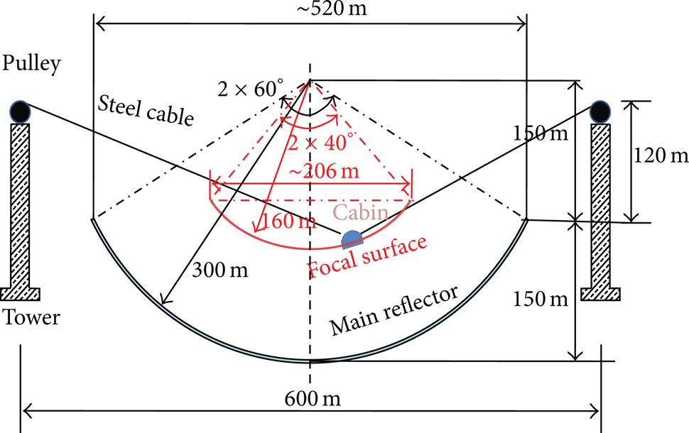
Cable-driven parallel robots have many important applications over the past decade. One is verified in the Five-hundred-meter Aperture Spherical radio Telescope (FAST) which is being built in southwest China [1]. The giant telescope has a relatively light airborne focus cabin carrying the precise expensive feed receivers to observe stars in the sky. Because of its large size, it is very difficult to build a solid support structure between the cabin and the ground. Flexible cables, however, provide the possibility and further conveniences beyond other means: light weight, very large ranges of motion, and little inertia. The cable-driven parallel robot used in the FAST telescope might be the largest robot over the world, as shown in Figure 1. As the end effector, the 30-ton focus cabin is supported and driven by 6 parallel steel cables so that it can move in a large calotte, so-called focal surface, which is about 206 meters in aperture. The 6 steel cables are, respectively, suspended by 6 steel towers more than 100 meters high and equally spaced on a circle of 600 meters in diameter. Each is driven by a capstan motor with the common tension force reaching tens of tons.

An overlook of FAST telescope.
The FAST cable-driven parallel robot is a typical incompletely restrained parallel mechanism (IRPM) similar to the Skycam [2]. The gravity plays as the seventh cable to fully constrain the 6-degree-of-freedom (6-DOF) cabin. Obviously in this case the sagging effect should not be neglected for the 6 steel cables. Although the FAST robot has huge size, this fact makes it mainly different from many other fully or redundant restrained cable-driven parallel mechanisms, such as RoboCrane [3], FALCON [4], and Tethered aerostat (LAR telescope) [5].
One important issue on cable-driven parallel robot is the orientation planning of end effector, as investigated in quite a few literatures [6, 7]. For the FAST case, all planned trajectories for star observations can be held in the focal surface, as shown in Figure 2. However, the cabin orientation is still left to be optimized from all the possible solutions with regard to both the pointing requirement of the telescope and the equilibrium condition of the cabin. During star observation, feed receiver equipped in the cabin is required to always point to the center of curvature (COF) of the focal surface. However, this requirement limits the orientation of feed receiver to special set value where the equilibrium condition of the airborne cabin is on many occasions hardly satisfied because of tension-only cables. A possible solution is to let the cabin orientation loose within a reasonable range and then rotate feed receiver in the cabin to compensate the caused angular error. Obviously the error as well as the cabin orientation should be counterweighted among easy compensation, cabin equilibrium and force allocation of the six cables. Besides, effective control strategies should be taken into account in which both position and orientation control have to carried out by 6 cable length variations. Decoupling of the 2 types of controls should also be carefully considered.
Section plane of FAST.
This paper first studies the optimal planning of cabin orientation on the FAST cable-driven parallel robot, looking for the interdependence between the cabin orientation and the 6 cable forces. Then a special control algorithm is proposed for both cabin position and cabin orientation where special attention is paid on adjusting cabin orientation in accordance with the optimal planning. Finally estimation on the control deviation of cabin orientation is discussed as well as its corresponding allowable force error for 6 cables.
2. Optimal Solution of Cabin Orientation
2.1. Mechanism Configuration
The kinematic diagram of the FAST IRPM is represented in Figure 3. The focus cabin is assumed to be a rigid end effector connected to the base by a set of 6 parallel steel cables. One end of each cable is attached to the cabin and the other end to a fixed pulley through which the steel cables are guided to the ground capstans. By adjusting the 6 cable lengths, the position and orientation of the cabin can be controlled to the set value.

Mechanism configuration of FAST IRPM.
Referring to Figure 3, a fixed reference frame, noted
Three special angles, namely, θ, φ, and ϕ, are introduced to describe the cabin orientation, as shown in Figure 3(b). The angle θ represents the cabin tilt, φ the cabin azimuth, and ϕ the cabin spin. The coordinate frame
2.2. Wrench Matrix
Assuming that the ith cable exerts a pure tension at the point C
i
, it can be written as t
i
where

with

where
2.3. Minimal Variance among 6 Cable Forces
The FAST IRPM is often redundantly actuated because of the inability of cables to work in compression. For a given wrench on the cabin with certain cabin position in its wrench feasible workspace, neither the cabin pose nor the 6 cable forces may have the unique solution. However, large force variance among 6 parallel cables is not acceptable for the cable-driving capstans in that the maximal force is often one of the calculation bases in the power layout of electric motors. Thus, a reasonable force allocation is to make the total force variances as minimal as possible in that stable power output may be anticipated.
Mathematically, the problem can then be formulated as follows:

where the symbol
2.4. Optimal Solution of Cabin Orientation and Cable Forces
Combining (2) with (4) a constrained optimization comes out mathematically, where (4) is taken as the object function, (2) as constraints, and the 6 cable forces and 3 orientation angles together as the variables to be optimized. Considering influence of cable sag, [8] further deduces equations of slack rope model in the formulation of this nonlinear quadratic program and gets the optimal solutions based on the Levenberg-Marquardt method. The solutions indicate a kind of optimal planning of cabin orientation around the whole focal surface.
Figure 4 draws the optimal cabin tilt θ as the cabin moves in the focus surface, showing its nearly perfect axisymmetrical distribution in a range of 0°~15°. But this value is still a little far from the ideal pointing. For example, the difference is nearly 25° when θ is equal to 15° at the surface edge. The optimal solutions further tell very small difference between φ and the pointing azimuth of star observation, and the optimal ϕ is near to zero (Figure 5). The fact proves that the cabin tilt θ is the main object for the compensation of cabin orientation, which is left to the rotator in the cabin (Figure 6).
Distribution of cabin tilt θ (°) on the focal surface.

Difference (°) between φ and azimuth of ideal pointing.

Distribution of cabin spin ϕ (°) on the focal surface.
Figure 7 draws the force distribution case of cable. And yet due to the symmetry it is easy to obtain a similar tension distribution of cables 2, 3, 4, 5, and 6 by simply rotating the figure counterclockwise with 60°, 120°, 180°, 240°, and 300°, respectively. The figure shows that the optimal cable tension varies continuously and smoothly. It also indicates that there is only one-to-one mapping from 6 cable tensions to the cabin position and orientation. A special orientation at a set cabin position is corresponding to a unique group of 6 cable tensions and vice versa.

Distribution of cable tension t1 (N) on the focal surface.
The optimal solutions for cable tension agree with the principle of minimal force variance. In the meantime the corresponding cabin orientations are the nearest to the ideal pointing. Therefore, they are recommended as the optimal orientation planning for the FAST IRPM.
3. Algorithm of Position and Orientation Control
The control task of the FAST cable-driven parallel robot is to track not only a given trajectory but also its attached optimal cabin orientation determined in Section 2. Both two control targets are realized via adjustment of 6 cable lengths. It is therefore important to decouple these two kinds of controlled variables. Two kinds of feedback data, cabin position and cable forces, are applied for the position and orientation control, respectively. The outputs of control are set as the velocities of 6 capstan motors. For each cable the output winding speed V is comprised of three parts, as described in the following:
where VT is the theoretical output component, VFBP is the component with regard to position feedback, and VFBF is the component with regard to force feedback. Here positive velocity makes cable length increase. In the calculation of cable length variation, simple straight-line model is used instead of the complex cable curve because the control period is small enough and calculation errors do not accumulate.
3.1. Theoretical Component
The theoretical velocity component is the main part of the total control output. As shown in Figure 8, assuming that the cabin positions are known at the moment (Ra0) and the next (Ra1) within a control interval, h, the theoretical velocity component VT may be calculated as follows:

where dL1 is the variation of cable length, as shown in Figure 8.

Calculation of control output.
3.2. Component with regard to Position Feedback
The usual proportional, integral, and differential (PID) algorithm is applied to calculate the component with regard to position feedback. Then the position feedback is calculated as follows:
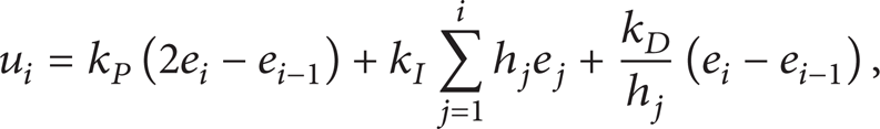
where the coefficients k P , k I , and k D are the PID parameters determined via experiments; e i is the error between the ideal cabin position in the reference trajectory and the measured cabin position, as shown in Figure 8. Because of the PID algorithm, the position feedback is calculated beginning with a new position (Ru1) with Ru1 = Ra1 + u1 instead of the measured position Rr0. Therefore, the component with regard to position feedback is calculated as follows:

3.3. Component with regard to Force Feedback
The component with regard to cable force feedback is calculated as follows:

where the feedback coefficient k f is the parameter determined via experiments, Fr0 is the measured cable force, and Fa0 is the reference cable force corresponding to the planned cabin orientation as shown in Figure 7. Note that (9) directly connects the force feedback with the orientation control.
The abovementioned control algorithm is programmed and applied in the 50 m scale Miyun demonstrator [9]. Note that more weight is put on the position control in the algorithm. Comparatively the position control is simple and its feedback has better precision. However, the orientation control is also indispensable in that it keeps conveniently a relatively balanced force allocation among the 6 cables as well as the optimal orientation for star observation.
4. Error Estimation of Orientation Control
Note that the orientation control given in Section 3 depends on the feedback of force sensors and the planned cabin orientation. However, in many occasions force sensors usually have limited precision and resolution compared with its measuring range, which disrupts the application of (9) in the control. Assuming that the tension feedback has several tons of error for the 6 cables, the controlled cabin orientation may deviate from the planned value. So the question comes out to determine the relation between the force error and the orientation deviation.
The problem can be formulated as an optimization similar to Section 2. Here the optimization aims to find maximal orientation deviation corresponding to the given tension error of the 6 cables.
4.1. Maximal Variance among 6 Cable Forces
As indicated in Section 2, a special orientation is corresponding to a unique group of 6 cable tensions and vice versa. Moreover, the planned orientation responds to the minimal tension variance. It is reasonable to assume that maximal tension variance may be corresponding to the maximal orientation deviation. Mathematically, the problem can then be formulated as follows:

where C is a positive constant which assures the object Π > 0 for the convenient application of the Levenberg-Marquardt method. Because of the measuring error in force feedback, in (10) the deviations of 6 cable tensions should be less than the assumed error Δt i as follows:

where t0i is the optimal tension of the ith cable corresponding to the planned cabin orientation, also the reference value from which the tension deviation is measured.
4.2. Optimal Solution of Orientation Deviation
Similarly, combining (2) with (10) and (11) a constrained optimization comes out mathematically, where (10) is taken as the object function, (2) and (11) as constraints, and the 6 cable forces and 3 orientation angles together as the variables to be optimized. Considering the influence of cable sag, this nonlinear quadratic program is further formulated and the optimal solutions are obtained based on the Levenberg-Marquardt method.
The solutions of the cabin orientation can be further changed into the orientation deviation of the cabin as follows:

where Ψ and Ψ0 are, respectively, the actual and planned orientation vectors of the cabin as shown in Figure 3.
The orientation deviations are diagrammatically displayed in the following figures. They further prove the close relation between the maximal orientation deviation and tension errors. Furthermore, the increase of tension error is inevitably followed by the upsoar of orientation deviation.
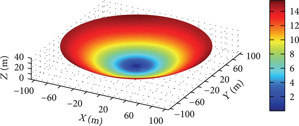
Figures 9(a), 9(b), and 9(c) show the orientation deviation of the cabin corresponding to Δt i = 50 KN, Δt i = 40 KN, and Δt i = 30 KN, respectively. In the case of Δt i = 50 KN, the figure shows great orientation deviation up to more than 25° as the cabin moves near the edge of the focal surface. Obviously it is unacceptable. In the case of Δt i = 40 KN, however, the figure shows a great decrease with the maximal deviation less than 3.5°. The phenomenon indicates that an inflection tension error may exist between 40 KN and 50 KN within which the orientation deviation is controllably proportional to the tension error. In the case of Δt i = 30 KN, the maximal deviation of the cabin orientation further decreases to less than 1° and even less than 0.5° in the most area of the focal surface. This result is quite favorable for the orientation control. Moreover, the error rate is applicable for many force sensors relative to the full range of 50 tons. It is reasonable to take 30 KN as the critical allowable value in selecting force sensors.

Distribution of orientation deviation δ (°) on the focal surface.
Note that the above analysis is completely based on kinematics which gives steady state solutions, so the orientation deviation in discussion does not include the error due to dynamics. It should be the next work of study.
5. Conclusion
A kind of huge incompletely restrained cable-driven parallel robot is introduced and studied on the optimal orientation planning, control, and the deviation estimation.
The planned orientation is the solution of a constrained optimization which takes the balanced allocation of 6 cable tensions as the object and the conditions of cabin equilibrium as the constraints. The solutions indicate that there is only one-to-one mapping between 6 cable tensions and the cabin orientation. A special orientation is corresponding to a unique group of 6 cable tensions and vice versa.
The position control plays the main role in the control algorithm of the FAST IRPM. However, orientation control is also indispensable and relatively complex in that the control output depends on the planned tensions and force feedbacks of the 6 cables.
Orientation deviation may be estimated according to the feedback error of cable tensions. It is the solution of a constrained optimization which takes the unbalanced allocation of 6 cable tensions as the object and the conditions of cabin equilibrium and the deviation range of the cable tension as the constraints. The critical tension deviation, 30 KN, is suggested with which the orientation deviation is controllable.
Conflict of Interests
The authors declare that there is no conflict of interests regarding the publication of this paper.
Footnotes
Acknowledgment
This research is supported by the National Natural Science Foundation (NNSF) under Grant nos. 10973023, 11203048, and 11103046.