
Abstract
An automotive drive shaft is used in a front drive transmission vehicle for transmitting rotary movement from the gearbox output shaft to the wheels with a constant velocity. This paper presents the kinematic model of ball joint and tripod joint with consideration of clearance and proposes a simplified dynamics model of the drive shaft. The simulation of the dynamics model is given by the measured data. Also, the abrasive wear of the ball type joint is tested on the experimental setup with consideration of full loading. The results show that the dynamics of the motion will be affected by the clearance when the loading changes its direction. The motion will be stable due to the damping. It can be found that the abrasive wear of ball joint largely depends on the relative sliding velocity from the experiments. This will probably affectthe dynamics performance and the impact force, which will also cause the other type of failures.
1. Introduction
An automotive drive shaft is used in a front drive transmission vehicle for transmitting rotary movement from the gearbox output shaft to the wheels with a constant velocity. In general, it is composed of three parts: a fixed type joint, plunging type joint, and intermediate shaft. A ball joint is designed as the fixed type joint for vehicle steering on the wheel side without axial shaft movement. And a tripod joint is designed for allowing the axial movement or plunging of the shaft in order to absorb the axial vibrations initiated from the engine and transmission side. The plunging tripod joint is close to the gearbox, while the ball joint is close to the wheel.
The ball type joint consists of outer and inner races, a cage, and six balls which are equally arranged at 60° intervals fitting into matching half grooves on the two races. The tripod joint consists of an outer housing, which is formed with 3 track grooves extended along the shaft's axis, and a central spider, which is composed of 3 trunnions equally spaced at 120° circumferential intervals supporting needle and spherical roller assemblies, as shown in Figure 1.

A typical drive shaft for front drive transmission vehicles.
It has been found that the ball type joint is usually failure caused by abrasive wear. This is the motivation to conduct this study. A ball type joint comprises outer and inner races, a cage, and six balls equally arranged at 60° intervals fitting into matching half grooves on the two races, as shown in Figure 2.

A ball typical joint in a front drive shaft.
Kimata et al. [1] proposed an analytical equation based on dynamics to evaluate the effect of the frictional forces acting on the inside of a fixed ball joint and double offset joint. Hayama [2] started to investigate the dynamic motion and forces generated on a ball joint using the ADAMS program with a consideration of the Hertzian contact theory. However, the friction forces between the internal parts were not taken into consideration. Serveto et al. [3] showed that the sixth component of the secondary torque generated by the ball joint model during torque transmission could produce acoustic beats with the vibration of the engine. He also found that the inertia torque was negligible with respect to the high transmitted torque. Philpott et al. [4] presented a two-phase circular regression algorithm for extracting wear profiles from ball type joint. However, it is quite important to find out the root cause of abrasive wear in theoretical approach. Lee and Polycarpou [5] investigated diverse researches on the frictional characteristics of the roller in a tripod joint through analytical and experimental approaches. Mariot et al. [6] also suggested a mathematical model introducing a viscous and a Coulomb friction approach to the kinematic analysis of a tripod joint. Watanabe et al. [7] developed a closed-loop equation for the end-motion type of tripod universal joints and simulated the normal force acting on the roller groove. Moreover, Lim et al. [8] analyze the drive shaft coupling of the ball and tripod types of constant velocity joints.
However, there has been little investigation on a complete analysis of the ball joint and tripod joint coupling assembly. Therefore, a fully integrated model of the drive shaft is needed to lead a solid foundation for investigating of the front drive shaft. In this paper, the kinematic model of the two types of joint with consideration of the clearance and a coupling dynamics model are proposed in Section 2. The dynamics simulation is given by using the measured clearance in Section 3. In Section 4, the abrasive wear of the ball type joint is experimentally studied. Finally, the conclusions are given in Section 5.
2. Kinematic Model
As the drive shaft assembly is composed of three parts: a fixed ball type joint, a plunging type tripod joint, and a shaft, it is required to model the assembly in detail for the investigation of the dynamics performance. The models of two joints are presented as follows.
2.1. Ball Type Joint
Qi et al. [9] presented the kinematic model of ball type joint. The typical ball type joint can be illustrated in Figure 3. O is the interaction point of input axis and output axis. The distance between the center point of the ball P and the center of the outer race is r, the same as to inner race. And, therefore, ΔpO1O2 and ΔOO1O2 are isosceles triangle. C is the midpoint of line O1O2, t s and t r are unit vectors in the plane of ΔpO1O2,n s is the normal vector of plane ΔpcO. The vector in the direction of C and O1 is
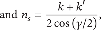
where k and k′ are the vectors of input shaft and output shaft.

Illustration of a typical ball type joint.
The vector of Oc is

The distances between the center of the balls and P are

It means that the ball is distributed in the circle (P, r s ). To describe the center of the ball, the coordinator system is set up with the original P (n s , r s , t r ). The vector between the center of the ball and P is

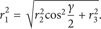
where r2 = esin(γ/2) + r s cosθ and r3 = r s sinθ.
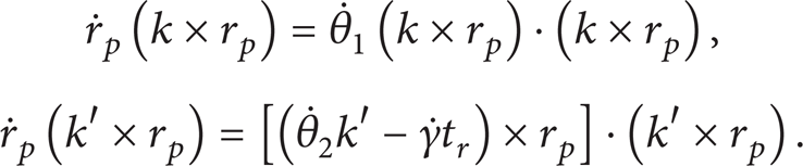
Assume that the input shaft is with the transient angle position of θ1 and rotating velocity of

where
Vector k × r
p
is with the same direction of the normal vector of the race. Also, the component of relative slipping velocity
For a given angle to the input shaft θ1 and a constant angle of γ, the variables of the output angle θ2 and the ball position angle θ can be determined by the above equations.
From (1) and (3), the vector of input and output shaft can be rewritten as
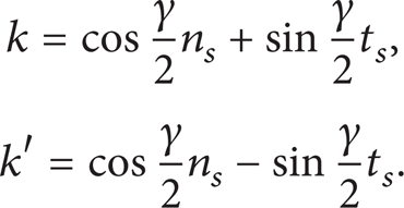
Because the vector of input shaft k is fixed, the output shaft is rotating along vector t
r
with the velocity of
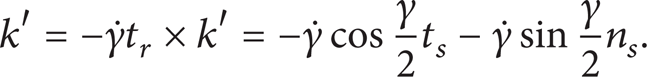
Substituting (1) and (2), we can get

Substituting the above equations into (5), the velocity of the ball can be rewritten as

From the geometric relation, the distance between the ball and input shaft is
The component velocity of the ball in the direction of t s and t r can be obtained, respectively, as follows:

The changing rate of the distance of the ball and C is

Therefore, we can get

From (14), we can easily prove that

where C1 is the clearance of the ball joint.
2.2. Tripod Type Joint
Tripod type joint was invented in 1910, and many researches were focused on studying its kinematic model. Kinematics of the tripod joint has already been illustrated in Figure 4 [10]. Using Euler angles Ψ, δ, and θ, the orientation matrix of the tripod with respect to the tulip is given by

and due to the 120° respective orientation of the trunnions in the tripod plane, it has been shown that ψ = − θ. Since the joint angle δ always keeps small,


Illustration of tripod type joint.
Lee and Akbil [11], and the authors also [10], have given the kinematics closure equations between input angle φ and output angle θ for a given angle δ:

where e is the offset between tripod center and tulip shaft projected in the tripod plane and

Since the joint angle δ and the deviation φ − θ from a CVJ have R3 behavior, they can be developed in a Fourier series limited to the first term:

The constants δ m , δ0, and θ0 can be analytically or geometrically determined [8]. Since δ0 is negligible versus δ m , we can write the following:

Approximations of δ0 and θ0 lead to

Based on the theory mentioned above, the kinematic formula can be rewritten as follows:

However, this model is without the consideration of clearance. If we take the clearance into account, the nonlinear model can be described as

where C2 is clearance of the tripod joint.
2.3. Simplified Dynamics Model of the Front Drive Shaft
It has been reported that the dynamics performance of the joint can be neglected when considering the dynamics performance of the front shaft. Then the front shaft can be illustrated in Figure 5.

Simplified dynamics model of a front drive.
The dynamics model of the system can be described by the following equations:

where K1 and K2 are the equivalent stiffness of the drive shaft, assuming that K1 = K2, D1, D2, and D3 are the damping coefficient, M i is the torque generated by the engine, R is the radius of the wheel, F f is the friction force between the wheel and the ground, J1 is the effective inertia from engine to the gear box, J2 is the inertia of the drive shaft, and J3 is the effective inertia of the wheel.
3. Simulation
The models mentioned above are not considered the clearances. The clearances are really related to the dynamics performance of the transmission system. It has been conducted to measure the clearance in the test bench shown in Figure 6. The clearances of the ball joint and the tripod joint have been measured, as shown in Table 1.
The clearance measured by experiments.


Experimental setup.
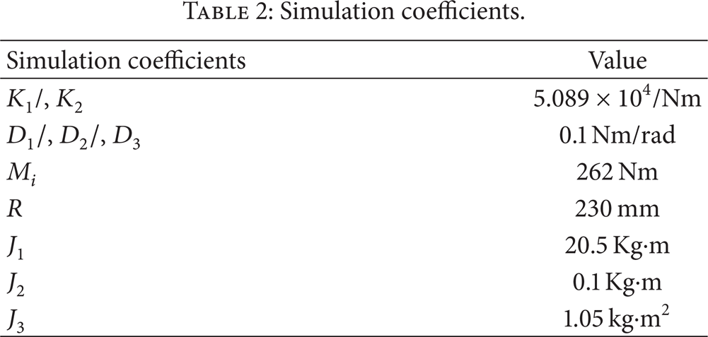
By the above model, the simulation program is developed in MATLAB/Simulink as shown in Figure 7. We simulate the dynamics system of the proposed model with the given coefficients in Table 2. The input torque and the output torque of the driven shaft are presented in Figure 8 as well as the rotating velocities.
Simulation coefficients.
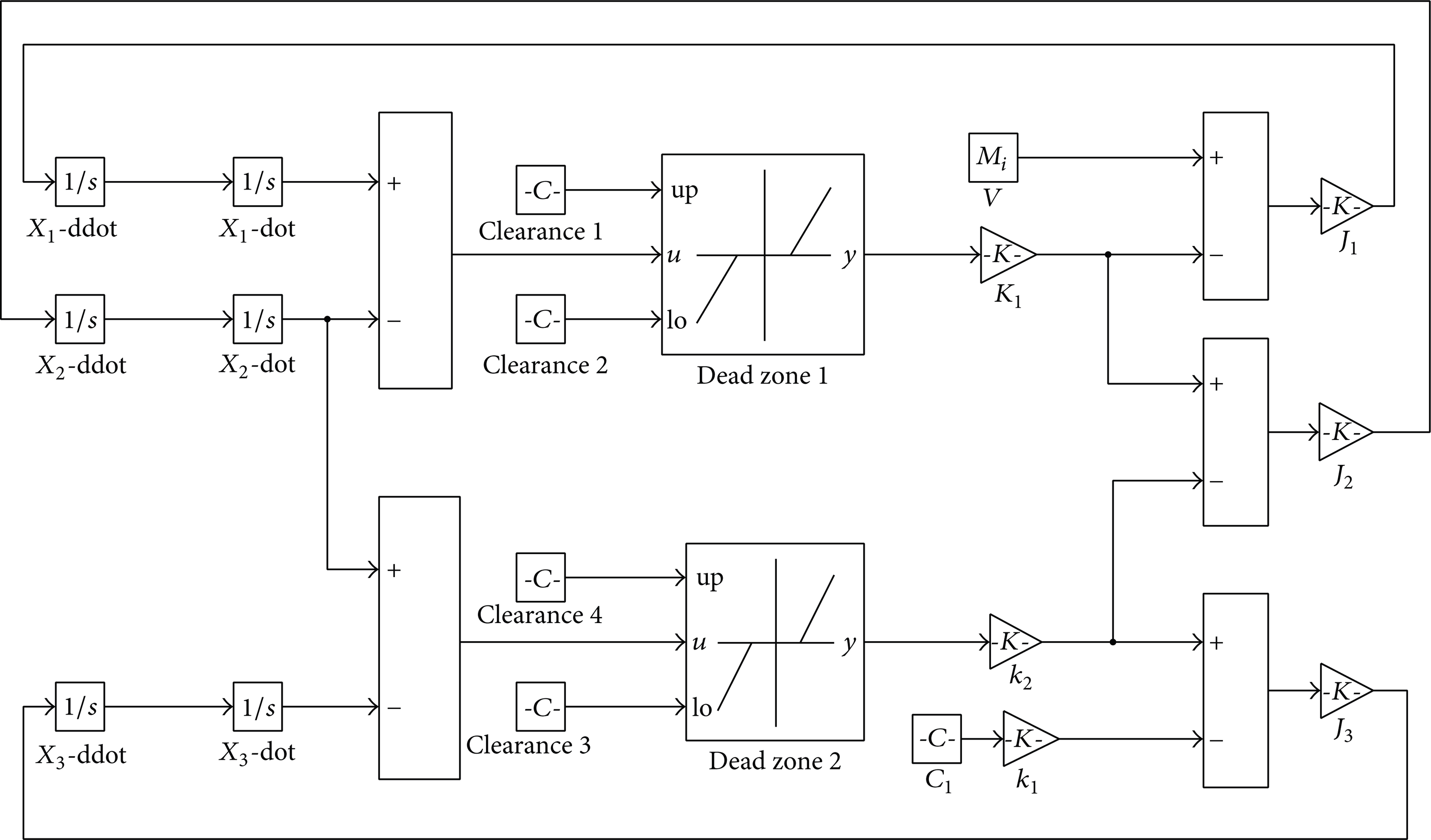
Numerical program coded in MATLAB/Simulink.
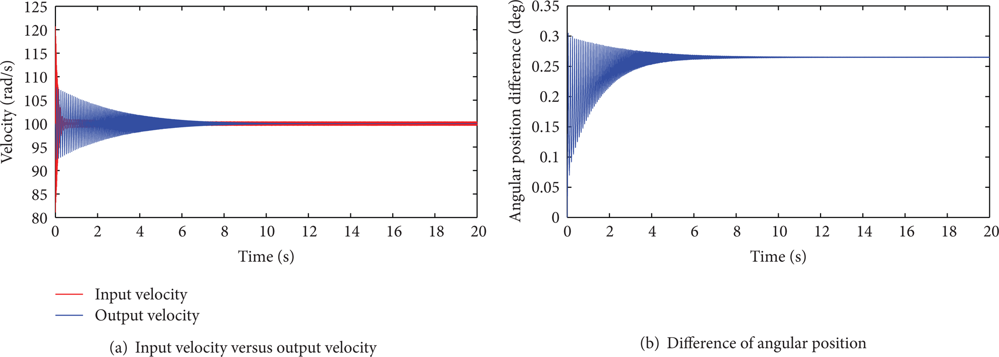
Simulation results.
4. Abrasive Wear of Ball Type Joint
As given above, Qi et al. [9] have proved that constant velocities of the input shaft and output shaft are achieved. It has been found that the “constant speed” largely depends on the geometric shape of the race and the ball. Also, it has significant relative motion between the ball and the races, as well as the ball and the cage in each cycle. The previous studies have shown that it is relative to the abrasive failure. The formula for the calculation of the relative velocity between the tracks and balls has been proposed by Li [12]. The simplified model of the relative velocity between the ball and the outer race track Δω0 and the relative velocity between the ball and inner race track Δω i are
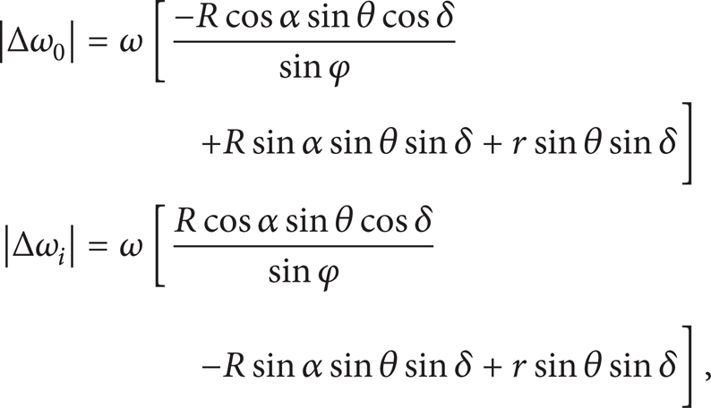
where R is the radius of the ball; r is the distances between the center point of the ball and the center of the outer race; ω is the input/output velocity of the shaft; δ is input angular position of the ball; θ is the angle of the CV joint; φ is defined as the angle of joint; α is the contact angle between the races track and the ball, in general, = 15°~17°.
The experiment setup is illustrated in Figures 9 and 10. It composes two motor divers and two loaders, as well as two torque sensors. Four front drive shafts can be tested in the experimental setup in the meantime. In this experiment, the parameters are given in Table 3.
Experimental parameters.


Illustration of the experimental setup.
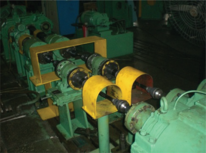
Experimental setup.
With the experimental conditions given in Table 3, (26) can be used for calculating the relative slipping velocity of the ball joint. With MATLAB, the simulation could be done easily, as given in Figure 11.

Relative slipping velocity of the ball joint.
The quantification of wear of the parts was inspected by visualization using a obtical microscope. Experiment result of the ball joints is summarized in Table 4 and the photos of the key components are shown in Figure 12. It can be found that the ball, the outer race track, and the inner race track have high wear rate than cages. This has been also reported in [4]. This phenomenon also reflects the theoretical study of relative speed.
The experiments results.
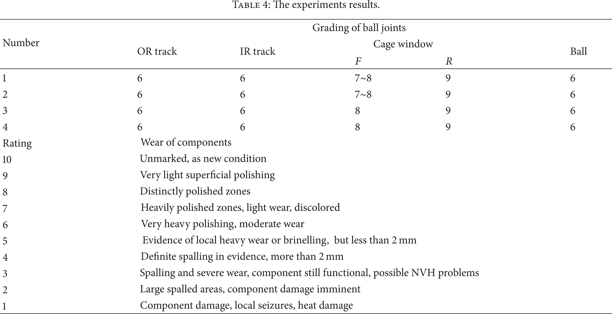

Photo of the components.
5. Conclusions
This paper presented a simplified dynamics model with the consideration of clearance based on the kinematics motions of the ball type joint and tripod type joint. Also, the clearances are measured by experiments. According to the results, the following conclusions are drawn.
The clearances should be considered in the dynamics study, as it has impacted the performance.
The presented dynamics model can be used for quick prediction of the front drive shaft. But the accuracy of the model should be further improved in the future.
The abrasive wear of the ball type joint largely depends on the relative velocity between the ball and the races/cages with a constant loading. It is suggested to improve the surface hardness of the component that resists the abrasive wear.
It has been found that the clearance is significantly larger than its initial value. This is related to the abrasive wear of the components. This will probably affect the dynamics performance and the impact force, which will also cause the other type of failures.
Experiments with various relative velocities should be conducted for verification of the theoretical model in the future research.
Conflict of Interests
The authors declare that there is no conflict of interests regarding the publication of this paper. Also there is no conflict of interest regarding the support of State Key Laboratory of Vehicle NVH and Safety Technology (no. NVHSKL-201005).
Footnotes
Acknowledgment
The presented research is supported by the open foundation from State Key Laboratory of Vehicle NVH and Safety Technology (no. NVHSKL-201005).