
Abstract
Unsteady flow structures can lead to severe vibration in centrifugal pump if the eigenfrequency of the rotor is equal to excitation frequency. In order to reduce rotor-stator interaction in centrifugal pump, a special slope volute was proposed. This paper explores the use of numerical simulation method to illustrate unsteady pressure pulsation and rotating stall characteristics under 0.05ΦN–1.4ΦN working conditions. Spectrums of pressure pulsation signals at different flow rates were analyzed. Relative velocity distributions interior blade channels were also studied to clarify correlation between flow structure and pressure spectrum. At high flow rates, predominant components in pressure spectrums always correspond to blade passing frequency (fBPF). With decreasing of flow rate, partial flow separates from suction side of blade at 0.6ΦN, but the separate structure has little impact on pressure spectrum. From 0.8ΦN to 0.6ΦN, peak values in pressure spectrums are still located at fBPF. At rotating stall working conditions, multiple vortex structures exist in impeller, which develop with rotating impeller showing intensive unsteady properties. And partial blade channels are blocked severely. Due to the unsteady stall cell structure, stall frequencies are generated in pressure spectrum, and the excitation frequencies are different at variable flow rates.
1. Introduction
Due to its great effect on centrifugal pump design and vibration characteristics, unsteady flow fields interior centrifugal pump has been investigated for years [1]. Different types of unsteady phenomena exist in centrifugal pump, including rotor-stator interaction, flow separation, vortex shedding, and cavitation. At noncavitation operating conditions, rotor-stator interaction keeps the predominant role in causing unsteady pressure fluctuation and low frequency vibration signals in centrifugal pump [2]. The excitation frequency depends on blade number and rotating speed of impeller, and it is well known as blade passing frequency (fBPF). Many factors affect unsteady pressure pulsation in centrifugal pump, for instance, geometric parameters of blade, clearance between impeller and volute tongue, and the match characteristics of impeller and volute [3, 4]. Many researches have been done in order to reduce pressure fluctuation in centrifugal pump, and most of them are focusing on parameters of impeller. Some special structures of impeller have been proposed, for instance, the splitter blade [5]. However the structure of volute is rarely taken into account to reduce rotor-stator interaction.
When centrifugal pump operates at off-design flow rates, flow out of impeller does not match the volute causing pressure pulsation characteristics to change. At low flow rates, rotating stall phenomenon may occur in interior impeller channels, and it is one of the most important sources causing low frequency vibration signals in centrifugal pump [6]. The stall cell transfers from one blade channel to the adjacent channel at a frequency usually lower than impeller rotating frequency. The frequency of stall is not determined by blade number of model pump [7]. Many researches have been done to illustrate rotating stall characteristics in centrifugal pump with vaned diffuser. Lucius and Brenner used PIV technology and numerical method to investigate rotating stall in a centrifugal pump with diffuser and found that several patterns of stall cells exist in blade channels [8]. Sano et al. studied rotating stall in a centrifugal pump with vaned diffuser. In that study, flow field, pressure distribution, and rotating stall features in diffuser were analyzed using CFD method [9]. Sinha et al. illustrated pressure pulsation and rotating stall in a centrifugal pump with vaned diffuser using experimental methods. However, rotating stall characteristics in a centrifugal pump with volute were rarely investigated [10, 11].
A special slope volute was proposed to reduce rotor-stator interaction in centrifugal pump. This paper attempts to clarify pressure pulsation and rotating stall properties in a centrifugal pump with slope volute. The diffusion section of volute has an acute angle with impeller axis. The shape and relative position of volute tongue change obviously compared with spiral volute [4]. Flow structures interior model pump was also obtained to verify the relationship between rotating stall characteristics and pressure spectrum.
2. Numerical Considerations and Modeling
2.1. Parameters of Model Pump
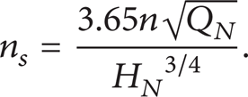
A centrifugal pump with slope volute was first designed. Radial size of volute periphery keeps constant, while the area of cross-section increases along axis direction. The main parameters of model pump are presented in Table 1. And specific speed is defined as in
Parameters of model pump.

2.2. Mesh Generation
Model pump contains four computational domains: pump inlet, slope volute, pump outlet, and impeller as seen in Figure 1. The relative movement between impeller and slope volute was solved by defining a pair of gird interfaces at the inlet and exit of the impeller. The quality of mesh has great influence on numerical simulation accuracy. ICEM was adopted to generate structure mesh cells of model pump in order to obtain precise unsteady flow structures and pressure fluctuation properties. Standard wall functions were used to dispose the complex flow field near the solid wall of model pump. Standard wall functions have strict requirement of the first layer height of grid [12]. To guarantee computational accuracy, grid cells near the solid wall were encrypted, especially on surface of blade, where significant pressure gradients or flow separation may easily occur. Numerical calculation results show that y+ distribution of the whole computational domains is within range of 10–200, which satisfies the requirement of standard wall functions. The total size of mesh finally used in calculation was 1.15 × 10⁶ after mesh independent check. Figure 2 shows structure mesh cells of impeller and slope volute.

Computational domains.

Mesh of impeller and slope volute.
2.3. Turbulent Model
Finite volume method (FVM) was used to deal with the governing equations. The commercial CFD code Fluent was used to solve Reynolds-averaged Navier-Stokes (RANS) equations. According to the research of Barrio et al., standard k-ε, RNG k-ε, standard k-ω, SST k-ω, and Reynolds stress model (RSM) were investigated on unsteady pressure pulsation characteristics in a centrifugal pump. In that paper, it was found that the results obtained from different turbulent models differ quite little, and the differences were lower than 1% [13]. So standard k-ε turbulent model was chosen considering its wide use and high calculation efficiency.
The length of inlet duct was 2 times of impeller diameter, where the velocity boundary condition was imposed. The turbulent properties at inlet boundary were set to turbulent intensity of 5% and hydraulic diameter of impeller inlet. A constant static pressure was imposed at outlet boundary and the value was 1.013 × 10⁵ Pa. Time-dependent term scheme was first order and implicit. First order upwind discretization scheme was adopted for convection terms and central difference schemes for diffusion terms. The coupling between pressure and velocity of model pump was solved by SIMPLE algorithm.
The steady numerical simulation results were first achieved at a given impeller position using moving reference frame (MRF) method. When the steady flow fields of model pump were obtained, the results were set as initial boundary conditions to compute the unsteady flow field using moving mesh model. The rotating speed of the impeller was 1450 r/min, and it kept constant at different flow rates. Time step was set to Δt = 1.15 × 10⁻⁴ s in order to have enough resolution of unsteady flow results [14]. So each impeller revolution will be calculated in a time sequence of 360 time steps. Unsteady convergence also has a great influence on the achieved results, and at least forty revolutions were achieved to guarantee numerical accuracy [15]. Fast Fourier transform (FFT) method was adopted to change time domain signals into frequency domain signals to analyze pressure spectrums under different operating conditions. Hanning window was adopted to reduce energy leakage during signal process [16].
Standard k-ε turbulent model is as follows:

where μ t is turbulent viscosity and Gκ is generation term of turbulent kinetic energy. One has

3. Numerical Results
3.1. Optimal Design of Slope Volute
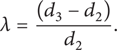
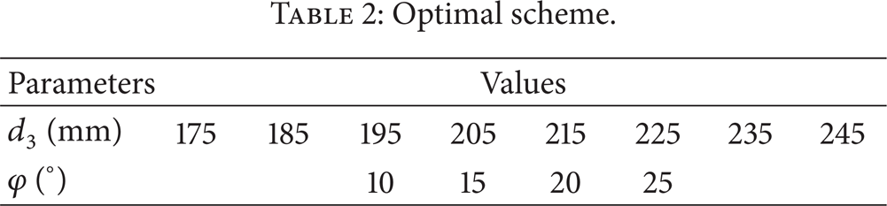
The slope volute is a new structure compared with the conventional spiral volute, which performs well in reducing pressure pulsation magnitude according to our previous work [17]. So optimal design of slope volute is essential to obtain the best efficiency and lowest pressure pulsation magnitude. Two important parameters of slope volute, the slant angle of diffusion section and the clearance between impeller outlet and slope volute inlet, were taken into account. Table 2 shows variable values of two parameters. Clearance rate was defined as in (4). Definition of slant angle was presented in Figure 3. One has
Optimal scheme.

Definition of slant angle.
Figure 4 shows efficiency of model pump at designed flow rate under variable slant angles and clearance rates. With clearance rate increasing, efficiency of model pump increases, it reaches the maximum value at λ = 0.308, and then it decreases. It has an increment of 2% from clearance rate 0.017 to 0.308. And the increment is 0.4% from 0.192 to 0.308. It is also evident that at slant angle 15° model pump achieves highest efficiency at different clearance rates.
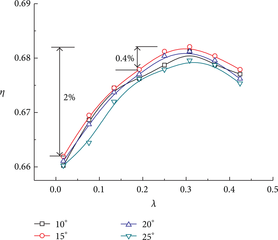
Efficiency of model pump at different parameters.
To obtain pressure pulsation signals, several monitoring points were arranged on periphery of slope volute as seen in Figure 5. The angles of different points increase along clockwise direction. Point P0 is located near slope volute tongue, which is set to 0°. Impeller rotating speed keeps a constant value of 1450 r/min, so impeller rotating frequency (f R ) is 24.2 Hz and blade passing frequency (fBPF) is 145 Hz.
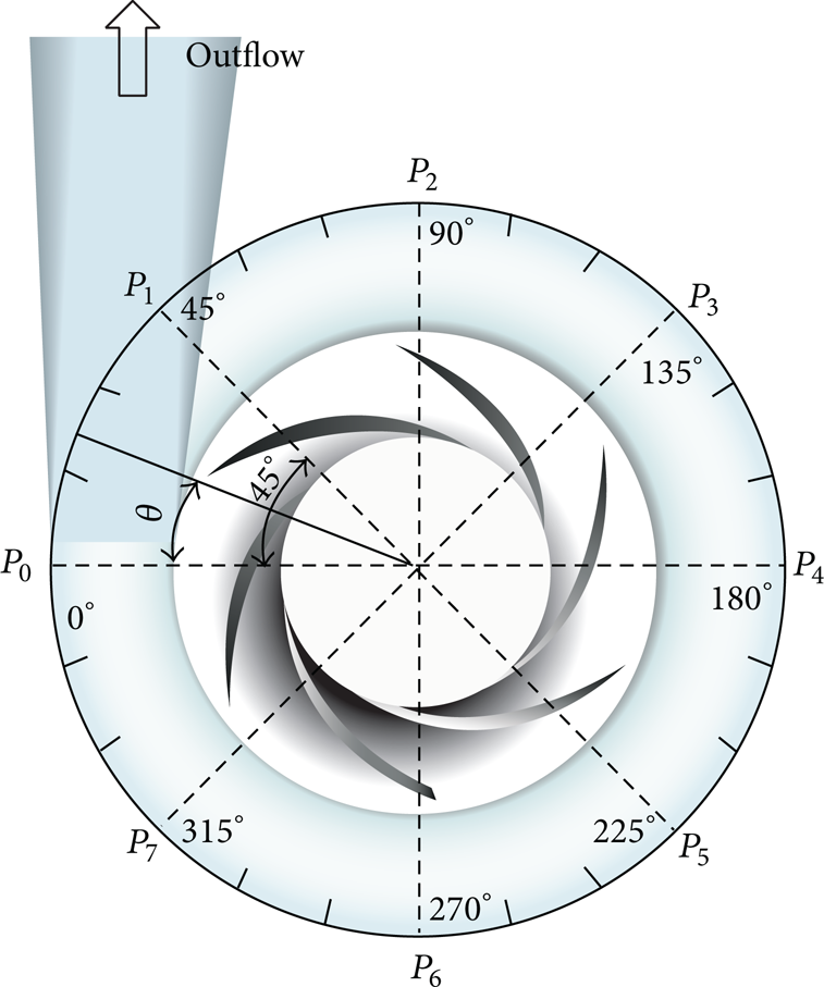
Monitoring points.
Pressure amplitude at blade passing frequency (fBPF) plays the predominant role in pressure spectrum at nominal flow rate. Pressure magnitude of monitoring point P0 under different clearance rates and slant angles was investigated. Figure 6(a) shows pressure magnitude at different clearance rates. And the slant angle φ of slope volute was set as 15° during different calculations. With increasing of clearance rate, pressure magnitude decreases significantly. In particular from 0.017 to 0.192, it drops rapidly. Then pressure magnitude changes slowly from 0.192 to 0.424. Figure 6(b) presents pressure magnitude at variable slant angles, and clearance rate was set as 0.192. It is clear that pressure pulsation amplitude reaches minimum value at slant angle 15°. From optimal results, it is concluded that both efficiency and pressure pulsation magnitude achieve best performance at slant angle 15°. With increasing of clearance rate, efficiency of model pump obtains maximum value at λ = 0.308, and pressure pulsation magnitude decreases significantly with clearance rate increasing. But clearance rate is limited to radial size of volute in some occasions. So clearance rate between slope volute and impeller outlet is suggested in the range of 0.134–0.308.
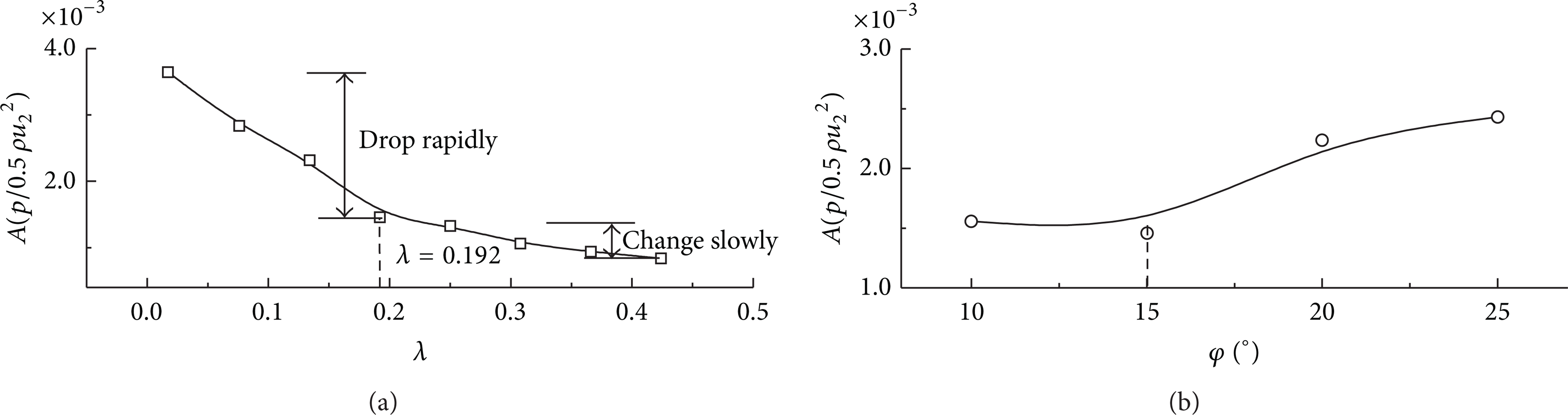
Pressure pulsation magnitude at fBPF.
Clearance rate 0.192 and slant angle 15° of slope volute were finally used in the following numerical calculation. Figure 7 shows numerical prediction of model pump performance. The best efficiency point of model pump is located around nominal flow rate. At low flow rates, positive slope phenomenon occurs in head curve of model pump, which indicates that rotating stall develops in impeller channels under these working conditions [18].

Numerical prediction of model pump performance.
3.2. Pressure Pulsation and Rotating Stall
Unsteady numerical simulation results were used to illustrate pressure pulsation and flow structures properties of model pump [19, 20]. Figure 8(a) presents pressure pulsation signals of different monitoring points at nominal flow rate. The period of rotating impeller is T = 0.0414 s. Pressure signals change periodically, and it is evident that six waves and troughs exist during one impeller revolution due to rotor-stator interaction. Pressure characteristics at different positions of slope volute differ obviously, and pressure amplitudes at P2 and P6 are much larger than that at P0 and P4. Figure 8(b) shows pressure spectra of the four monitoring points. As observed, the predominant components correspond to blade passing frequency (fBPF = 6f R ). Other spikes at harmonics of blade passing frequency (2fBPF,3fBPF) are also evident, but their magnitudes are much smaller than that at fBPF. Pressure magnitude at P2 reaches the maximum value, and it achieves minimum value at P4.
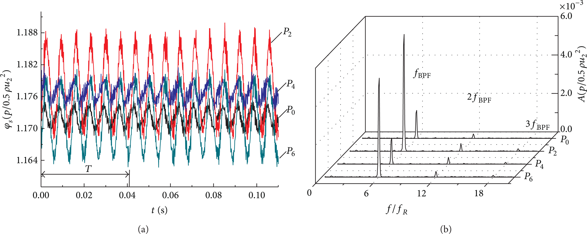
(a) Pressure pulsation signals and (b) pressure spectrums.
Root mean square (RMS) method was adopted to deal with unsteady pressure signals at different computing moments in order to analyze pressure characteristics on periphery of slope volute as shown in (5). Figure 9 shows RMS values of different monitoring points at three flow rates. When model pump operates at low flow rate 0.4Ф N , RMS value of pressure coefficient reaches minimum value at 45°. Then it increases gradually and achieves maximum value at 315°. From 45° to 315°, the change rate of nonuniform pressure signals is 6.8%. When model pump works at nominal flow rate 1.0Ф N , flow field is very uniform and separate region on blade suction side does not exist. Pressure coefficient achieves the maximum value at 90°, while it reaches minimum value at 315°. From 90° to 315° the change rate is 0.8%, which is much smaller than that at flow rate 0.4Ф N . At high flow rate 1.4Ф N , pressure signal changes significantly, and it obtains maximum value at 45° on the contrary. The change rate is 4.8%. From comparison of RMS values at different flow rates, it is concluded that pressure distribution on periphery of slope volute is very uniform and the change rate is really small at designed flow rate. At off-design conditions, especially at low flow rates, unsteady flow separate structures may easily occur on blade suction side causing nonuniform pressure distribution on periphery of slope volute, and the change rate is much larger than that at nominal flow rate. Also RMS values at different positions differ under variable working conditions. One has

where φ sn represents static pressure coefficients at different computing moments.

RMS of pressure signals at different monitoring points.
In order to analyze pressure pulsation features at different flow rates, pressure spectrums at two monitoring points were obtained. Figure 10 presents pressure spectrums of monitoring points P0 and P4 at three flow rates. It is found that peak values at blade passing frequency and their higher harmonics are evident, and pressure amplitudes at fBPF are much larger than that at other frequencies. When model pump works at high flow rates, flow strikes on pressure side of blade leading to vortex shedding. And pressure pulsation amplitude increases rapidly induced by the intensive chaotic flow structure interior impeller channels. With increasing of flow rate, pressure amplitudes at fBPF of two monitoring points are much larger than that at nominal flow rate.
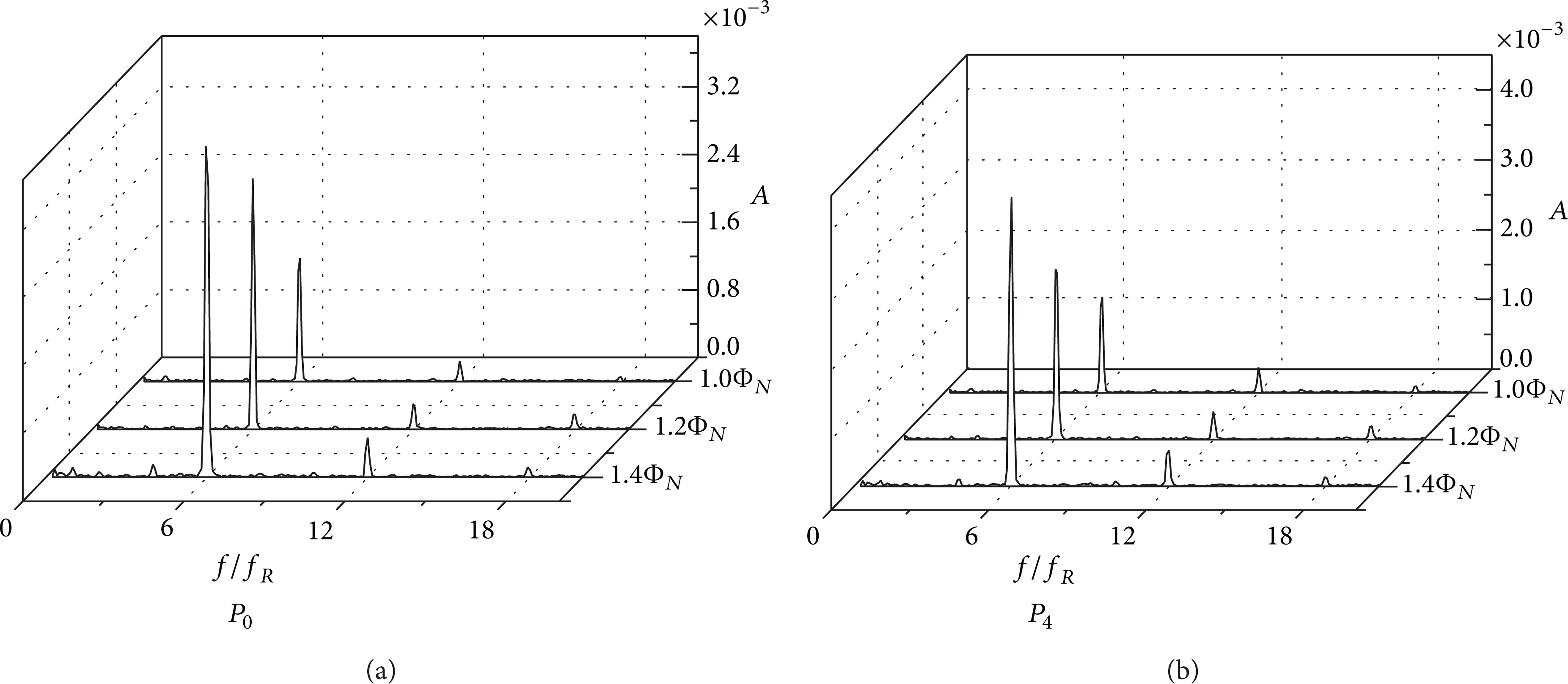
Pressure spectrums of P0 and P4 at three different flow rates.
With flow rate decreasing, pressure fluctuation characteristics change significantly. Figure 11 shows pressure spectrums of P0 and P4 under 0.4Ф N –0.8Ф N flow rates. When model pump operates at 0.6Ф N and 0.8Ф N , the predominant peaks in pressure spectra still correspond to blade passing frequency, and pressure magnitudes at other frequencies are rather small. When flow rate decreases further, rotating stall phenomenon occurs in impeller channels at flow rate 0.4Ф N leading to pressure spectrum characteristics changing. At monitoring points P0 and P4, stall frequency 0.5f R and its higher harmonics (1f R ,2f R ,4f R ) exist in pressure spectrums. And predominant peak in pressure spectrum no longer always corresponds to fBPF. In particular at point P0, the peak value in pressure spectrum is located at 4f R and its magnitude is almost 2.5 times of that at fBPF.

Pressure spectrums of P0 and P4 at three different flow rates.
To illustrate the correlation between flow structure and pressure spectrum, relative velocity streamlines at 0.6Ф N and 0.4Ф N are presented in Figure 12. At flow rate 0.6Ф N , flow field in impeller is rather uniform. With flow rate decreasing further, partial flow separates from suction side of blade at 0.4Ф N , which is located at middle of blade length. And reverse flow is generated at exit of blade at the same time. The reverse flow structure propagates from one blade channel to the adjacent blade channel with rotating impeller, which forms rotating stall phenomenon. The unsteady reverse flow structure has notable effect on pressure pulsation signals, and some extra excitation frequencies are induced in pressure spectrum. A cut plane of impeller is selected to verify the detailed unsteady information of flow field, and the relative position of cut plane is shown in Figure 13.
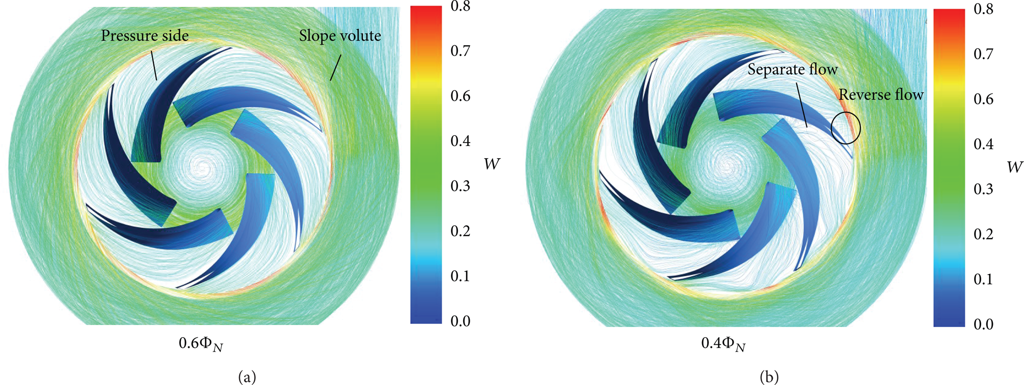
Relative velocity streamlines interior model pump at 0.6Ф N and 0.4Ф N .

Relative position of cut plane within impeller.
In order to investigate unsteady properties of rotating stall, relative velocity distributions at different computing moments on the cut plane are presented in Figure 14. At flow rate 0.6Ф N , separate structure starts to develop on suction side of blade, and the magnitude of relative velocity is much smaller within separate region. At different computing moments, the separate structures almost keep unchanged. From pressure spectrum of 0.6Ф N , it is known that only blade passing frequency and its higher harmonics are evident, and other excitation frequencies are not induced. So it is concluded that separate region on blade suction side almost has little effect on pressure spectrum. When flow rate decreases, flow structures interior blade channels alter obviously at 0.4Ф N . Flow structures in different impeller channels differ significantly at different computing moments. Flow patterns in channels 1, 2, 4, 5, and 6 are quite similar at different computing moments, and flow separate regions on blade suction side expand towards middle of blade channels. While in channel 3, flow structures interior impeller channels at different moments are different. At T moment, it is evident that stall cell first develops on pressure side of blade outlet, so two vortex structures exist at the same time in channel 3. And it rotates in counterclockwise direction. At t + 14Δt moment, stall cell at blade outlet shrinks. With the impeller rotating, at T + 30Δt moment, stall cell completely disappears. The unsteady development process of stall cell at blade outlet is crucial to pressure spectrum, which induces excitation frequencies (0.5 f R and its higher harmonics 1 f R , 2 f R , 4 f R ) existing in pressure spectrum.

(a) Relative velocity streamlines at 0.6Ф N and (b) relative velocity distributions at 0.4Ф N .
With flow rate decreasing further, Figure 15 shows pressure spectrums of P0 and P4 at flow rates 0.2Ф N and 0.05 Ф N . At flow rate 0.2 Ф N , extra frequencies exist in pressure spectrum due to rotating stall phenomenon. At point P0, excitation frequency 0.185 f R and its higher harmonics can be observed. And pressure magnitude at 4.1 f R is much larger than that at fBPF. At point P4, other spikes at higher harmonics of 0.185 f R are also evident, especially at 2.4 f R . When model pump works at flow rate 0.05 Ф N , several unsteady flow structures may exist in impeller channels at the same time. From pressure spectrum of P0, it is evident that two individual excitation frequencies 0.1 f R and 0.28 f R and their higher harmonics occur. At point P4, pressure magnitude at blade passing frequency decreases severely, and maximum peak value in pressure spectrum is located at 0.9 f R , the higher harmonic of 0.1 f R .

Pressure spectrums of P0 and P4 at 0.2 Ф N and 0.05 Ф N .
Figure 16 presents relative velocity streamlines of model pump at 0.2Ф N and 0.05Ф N . At 0.2Ф N , it is found that stall cell structure at blade outlet and separate region near blade inlet expand to middle of blade channel. And almost half area of each blade outlet region is occupied by stall cell causing partial blade channels blockage. When model pump operates at 0.05 Ф N , flow structures in blade channels change remarkably. Two different patterns of stall cells exist in blade channels. The large stall cell is located on pressure side of blade outlet, and the small stall cell is generated on suction side near blade outlet. The core of large stall cell is almost located at the middle of blade channel leading to channels being blocked severely. Some discrete excitation frequencies occur in pressure spectrum due to unsteady stall cell structures at blade outlet.

Relative velocity streamlines interior model pump at 0.2 Ф N and 0.05 Ф N .
Flow structures on the cut plane at flow rate 0.2 Ф N are presented in Figure 17(a). At T moment, flow structures in channels 5 and 6 are similar, and only one separate structure is generated near blade inlet. But in channels 1, 2, 3, and 4, stall cells develop on pressure side of blade outlet, and two vortex structures exist at the same time. The periphery of stall cell almost reaches middle of blade outlet. At T + 14Δt moment, in channel 4, stall cell at blade outlet starts to shrink. At T + 30Δt moment, stall cell structure disappears completely. Separate regions near blade inlet almost remain unchanged at different computing moments. From pressure spectrum of flow rate 0.2 Ф N , it is evident that 0.185 f R and its higher harmonics are motivated caused by the unsteady development process of stall cell at blade outlet.

(a) Relative velocity distributions at 0.2 Ф N and (b) relative velocity at 0.05 Ф N .
Figure 17(b) shows relative velocity distributions in impeller channels at flow rate 0.05 Ф N . As observed, separate regions near impeller inlet expand to middle of the channels, and half of blade inlet region is occupied by separate structure. At T moment, flow structures interior channels 1, 2, 3, and 6 are almost unanimous, and two separate vortex structures occur, locating near inlet and outlet of impeller, respectively. And stall cells are almost located at middle of blade outlet channels. In channels 4 and 5, another pattern of stall cell exists on suction side of blade outlet. It rotates in clockwise direction, and three vortex structures exist in blade channels at the same time. At T + 14Δt moment, stall cell at blade outlet splits into two different vortex structures in channel 5, and four vortex structures exist in blade channel. With the impeller rotating, at T + 30Δt moment, the two vortex structures at blade outlet merge into single vortex structure. From analysis of flow structures interior blade channels, it is found that multiple vortexes exist in impeller channels under this working condition. And vortex structure at blade outlet develops with rotating impeller forming rotating stall phenomenon. From pressure spectrum, it is observed that stall frequencies 0.1 f R and 0.28 f R and their higher harmonics exist. But it is impossible to distinguish the corresponding relationship between stall cells and stall frequencies, since pressure spectrum does not contain the time domain information of pressure signals. The predominant component in pressure spectrum no longer corresponds to blade passing frequency fBPF at full-stalled working conditions.
4. Conclusions
Numerical simulation method was used to analyze pressure pulsation and rotating stall characteristics in a centrifugal pump with slope volute. Some conclusions are made.
Static pressure distribution on volute periphery is not uniform. And the change rate of pressure signals reaches minimum value at designed flow rate.
At nominal and high flow rates, spikes in pressure spectrums always correspond to blade passing frequency. With flow rate decreasing, at flow rate 0.6 Ф N , separate region begins to form on blade suction side. But the separate structure has little influence on pressure spectrum and no excitation signal occurs in pressure spectrum.
At low flow rates, unsteady developing process of stall cell is captured, and it has great impact on pressure spectrum. The excitation frequencies differ at variable flow rates, and peak magnitudes at fBPF no longer keep the predominant role in pressure spectrums. Stall frequency 0.5 f R occurs at 0.4 Ф N , and 0.185 f R and its higher harmonics exist at 0.2 Ф N . In particular at 0.05 Ф N , two excitation frequencies 0.1 f R and 0.28 f R exist in pressure spectrum simultaneously.
Conflict of Interests
The authors declare that there is no conflict of interests regarding the publication of this paper.
Footnotes
Acknowledgment
The authors gratefully acknowledge the financial support of National Natural Science Foundation of China (51206063 and 51106066).