
Abstract
The hot blast stove is one of the most important equipment devices in the blast furnace iron making process. The temperature and duration of hot air are the crucial parameters to assess the performance of the hot blast stove. In order to sustain the desired high temperature air, it requires rapid completed combustion reaction, stable flue gas flow structure, and uniform temperature distribution throughout the regenerator. In the present work, a 3D numerical model with all essential turbulence, heat transfer, and combustion considerations has been developed to assess the performance of a typical hot air stove. The flow field of the whole domain and temperature distribution within the regenerator were simulated using the model. The predicted results show that the velocity at each nozzle varies substantially due to the uneven pressure distribution in cavity of the traditional hot blast stove, generating the eccentric vortex that leads to nonuniform temperature distribution in the regenerator. In order to solve this problem, a new structure design of top combustion regenerative hot blast stove is proposed. Numerical simulations were then carried out to compare based on the performance of the new hot blast stove design against the traditional hot blast stove.
1. Introduction
The hot blast stove is one of the most important equipment devices in blast furnace iron making process. The main challenge of the process is to steadily provide hot air to blast furnace. It is well know that improving the heat transfer efficiency of hot blast stove could bring various advantages to the process, including raising the hot air temperature, decreasing the coke ratio, increasing the output and the final quality of pig iron, and reducing the production cost and energy consumption [1, 2]. The regenerative hot blast stove is one of the widely adopted stoves in modern blast furnace process [3]. Figure 1 shows the schematic of top combustion hot blast stove.
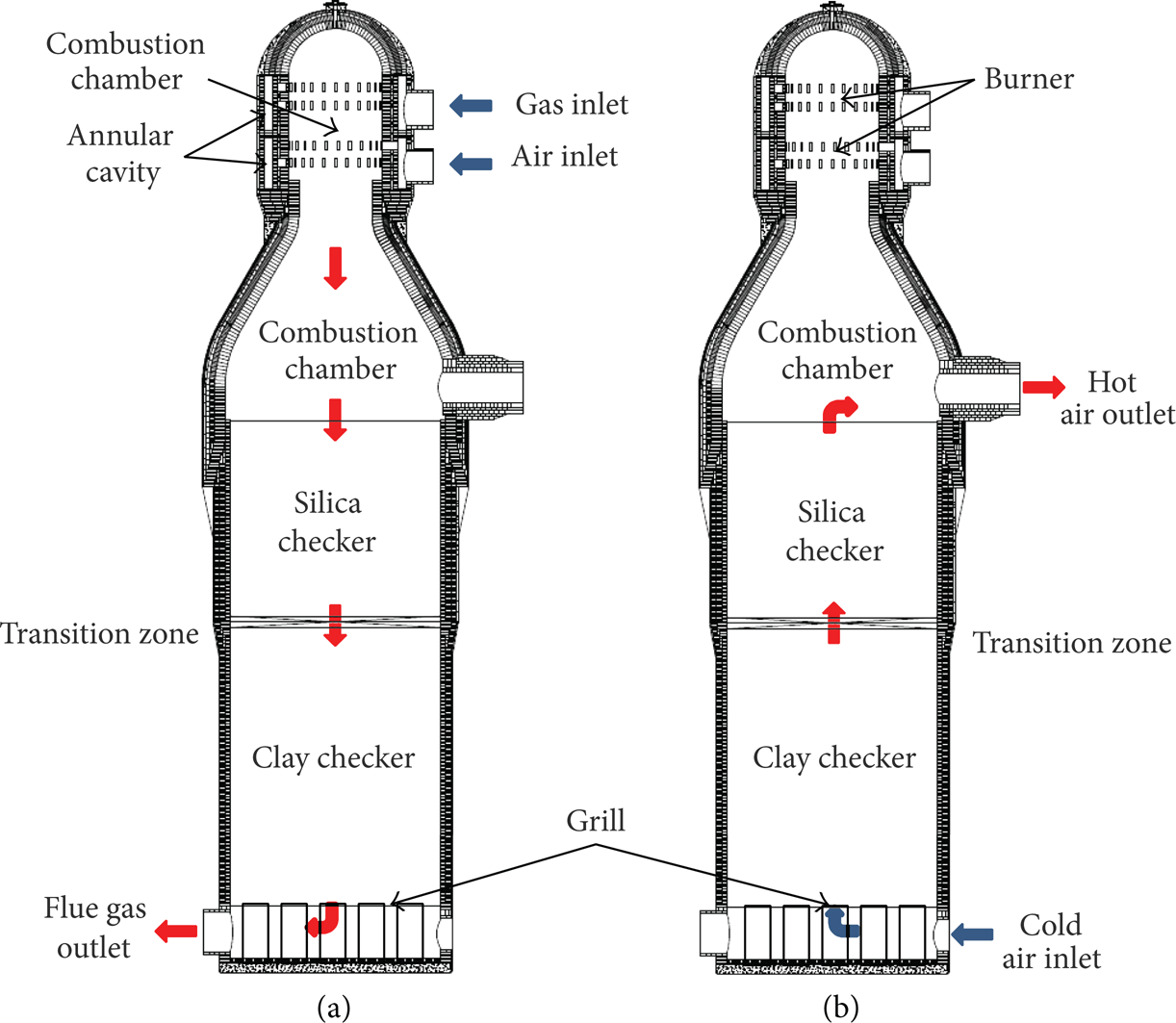
The schematic of top combustion hot blast stove. (a) The combustion process; (b) the air supply process.
The working cycle of the stove can be divided into two major processes: the combustion process and the air supply process. In the combustion process, the fuel gas and air are firstly mixed in the precombustion chamber and ignited. The combustion reaction produces high temperature flue gas which is then passing through and heating up the regenerator. In air supply process, cold air is supplied and passed through the high temperature regenerator and becomes hot air for the blast furnace. To ensure the continuous supply of hot air, most of the blast furnace usually configures with three or four hot blast stoves which work in alternative cycle between combustion and air supply process.
Despite the importance of the hot blast stove, there are still very limited studies that have been carried out. At first, the combustion phenomena in hot blast stove have been studied through experimental measurements. However, the experimental method not only requires a lot of manpower, material resources, and time but also suffers from substantial measuring errors due to the limitation of instrumentation and testing methodology.
From the late 1970s to early 1980s, due to the rapid development of computational hardware and numerical scheme, theoretical study and numerical simulation on hot blast stove have received more attentions [4–7]. At present, the “simple chemical reaction system” and “rapid chemical reaction” hypothesis was generally adopted to represent the hot blast stove combustion processes. For handling the turbulence, the k-∊ turbulence model and the k-∊-g model combined with Arrhenius formula were increasingly accepted as common practice to simulate the turbulent flow in the hot blast stove. Numerical studies have been carried out to simulate the performance of the burner, the combustion chamber, or even the whole blast stove [8–10]. Most of the efforts were made to investigate the influence of internal structure on the combustion, heat transfer, and turbulent flow process [11]. In the present work, a novel design of a top combustion regenerative hot blast stove has been proposed. To assess the performance of the proposed design, a three-dimensional mathematical model has been developed to simulate the associated fluid flow, combustion, and heat transfer phenomenon. Predicted performances of the existing design and proposed new design were also compared.
2. Mathematical Model
The combustion process of hot blast stove involves complex physical and chemical processes, including turbulent flow, chemical reaction, heat transfer, and species transport. This study aims to develop a comprehensive numerical model that considers all the relevant physical and chemical considerations in the furnace. The numerical model was developed based on the commercial CFD package ANSYS FLUENT. Based on the framework of ANSYS FLUENT, the following conservation equations were considered.
2.1. Conservation Equations of Fluid Flow
Fluid motion within the hot blast stove can be described by the three laws of fluid motion; the equations are as follows.
Continuity equation:

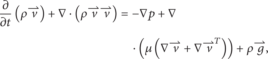
Momentum equation:
where p is fluid pressure, μ is the dynamic viscosity of a fluid, and ρ is density of fluid.
Energy equation:

where E = h − p/ρ + v2/2 is specific heat capacity; h is enthalpy, h = ∑
i
Y
i
h
i
;
It is well known that the Realizable k-∊ turbulence model is relatively stable, robust, and computationally efficient. Therefore, the Realizable k-∊ turbulence model was used to simulate the turbulent flow in hot blast stove:
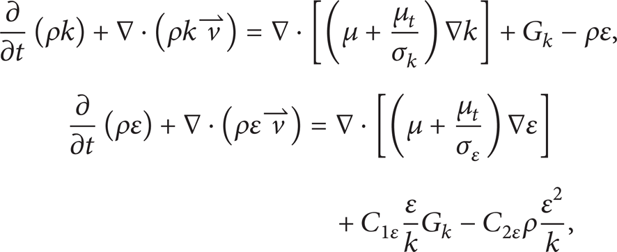
where G k is the turbulence kinetic energy produced by mean velocity gradient; C1∊, C2∊ are constant, C1∊ = 1.44 and C2∊ = 1.92 in present model; σ k = 1.0 and σ∊ = 1.3 are the turbulent Prandtl number for k and ∊, respectively.
2.2. Chemical Reaction Model
The species transport model was selected to represent the fuel gas and air transport and mixing characteristic. To order the track of the composition of the fuel and air mixture, mass chemical species are resolving explicitly by individual transport equation where convection and diffusion process of the species are considered. The general form of the transport equations for species is given as [12]
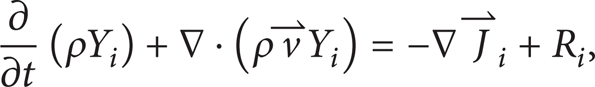
where Y
i
is the mass fraction of species i; R
i
is the net rate of production of species i by chemical reaction;

where Di, m is the mass diffusion coefficient of species i; μ t is turbulent viscosity; Sc t is turbulent Schmidt number (the default value of 0.7).
For handling the combustion process, the Eddy-Dissipation combustion model was adopted in the present study. The Eddy-Dissipation model assumes that the rates of chemical reactions of species are relatively fast and effective compared to the turbulent mixing rate. The combustion rate is therefore dominant by the turbulence mixing time scale. The resultant reaction rates are then determined by the local mass fraction of fuel, oxidant, and product. The characteristic of this model is that the reaction rate depends on the turbulent fluctuation decay rate; furthermore it can automatically choose component to control the rate [13]. Net rate Ri, r of components i produced by reaction r depends on the smaller one in the following two expressions:

where ϑi, r′ and ϑi, r′′ are the stoichiometric coefficients of the reactant and product in chemical reaction r for component i; Mω, i is the molecular weight of the components i; ρ is mixture density; N is the number of chemical species in the system; Y P is the mass fraction of the product P; Y R is the mass fraction of the reactant R; A and B are empirical constant, equal to 4.0 and 0.5, respectively; chemical reaction rate is controlled by large eddy mixing time scales k/∊. As long as the flow is turbulence flow (k/∊ > 0), the combustion will occur and does not need ignition source to start burning.
2.3. Radiation Model
In this study, the discrete ordinates (DO) radiation model is employed to model the radiative heat exchange between the combustion gases and internal surfaces of the hot blast stove. One of the main advantages is that the model tracks radiation rays over the whole solid angle using discrete ordinates within each computational grid. The model can be therefore applicable to complex geometries [14]. The DO model considers radiative transfer equation in direction

where
The nongray DO implementation divides the radiation spectrum into a series of wavelength bands, which need not be contiguous or equal in extent. The wavelength intervals are supplied by user and correspond to values in vacuum (n = 1). The RTE is integrated over each wavelength interval, resulting in transport equations for the quantity IλΔλ, the radiant energy contained in the wavelength band Δλ. The black body emission in the wavelength band per unit solid angle is written as

where F(0 → nλT) is the fraction of radiative energy emitted by a black body in the wavelength interval from 0 to λ at temperature T in a medium of refractive index n.
2.4. Porous Media Model
The porous media model can be used for a wide variety of single phase and multiphase problems, including flow through packed beds, filter papers, perforated plates, flow distributors, and tube banks. In present numerical model, the porous media model was used to simulate the flow and heat transfer process in the regenerator. From the numerical point of view, the present of porous media in the model is treated as an additional momentum sink in the governing momentum equations. For single phase flowing through a porous media, the momentum conservation equation can be described as
where γ is porosity; K is area porosity tensor; μ is the effective viscosity, is a sheet or a turbulent viscosity; the last term in this equation represents the viscous and inertial drag forces imposed by the pore walls on the fluid [15].
Furthermore, at the interface between porous medium and fluid, heat transfer is considered as thermal equilibrium where an effective conductivity is adopted to determine the conduction flux in the porous medium. The transient term includes the thermal inertia of the solid region on the medium:
where E f is total fluid energy; E s is total solid medium energy; ρ f is fluid density; ρ s is solid density.
2.5. Computational Domain and Mesh Generation
Figure 2 shows the visualization of the three-dimensional computational domain of the top hot blast stove. As depicted, the computational domain is composed by all essential parts of the stove, including the air inlet pipe, burner, the precombustion and combustion chambers, regenerator, and the furnace grills. The height of the furnace is 42 m, and the diameter of precombustion chamber and combustion chamber is 3.8 m and 10 m, respectively. The inlet pipes connect to four layers of nozzles insider the burner. Each layer consists of 25 nozzles evenly distributed around the circumvent of the burner. The top two layers are used for the fuel gas supply while the bottom two layers are for the air. The fuel gas is supplied through oblique nozzles with angle at 30°. For the air nozzles, straight nozzles are used for the first layer (i.e., upper layer) while the inclined nozzles with an angle of deflection of 30° are used for the second layer (i.e., lower layer). The combustion chamber, regenerator, and furnace grills are location under the burner (see also Figure 2(d)).

A three-dimensional computational model of top combustion hot blast stove: (a) the grid of hot blast stove; (b) the grid of burner and precombustion chamber; (c) the grid of nozzles; (d) the grid of grill.
A hybrid structured and unstructured mesh were generated throughout the computational domain. As shown in Figure 2, local mesh refinements were also employed to capture the local flow structure and combustion process at the nozzles and inside the burner. Based on the gird independence analysis, the final mesh with the total grid nodes of 7.76 million was used for numerical simulations.
2.6. Boundary Condition
All boundary conditions are set with reference to the typical operating conditions of an operating plant. In the combustion process, the fuel gas is supplied to the blast furnace at 200°C with the flow rate of 11.7 × 10⁴ Nm3/h. The composition of fuel gas is summarized in Table 1. Meanwhile, air is supplied at 180°C with the flow rate of 8 × 10⁴ Nm3/h. The flue outlet is considered as pressure outlet with the static pressure of 200 Pa. All surface walls are assumed as nonslip wall with the convection heat transfer coefficient of 15 W/(m2·K). The regenerator is composed of two types of checker brick (i.e., silica brick and clay brick). Detailed parameters of the checker bricks are tabulated in Table 2. Since this paper mainly focuses on the combustion process of the hot blast stove, the results of the air supply process are not presented.
Gas composition of blast furnace.

Parameter of checker brick.

3. Results and Discussions
3.1. Model Validation
Measurements from an on-site field test are used for model validation in the present study. In the field test, three thermocouples are set to measure the temperature within the blast furnace. As depicted in Figure 3, one of the thermocouples (i.e., point 1) is used to monitor the dome temperature. It is well known that the dome temperature is an important parameter for assessing the performance of the hot blast furnace stove. The dome temperature can be correlated to the hot air temperature based on some existing empirical equations [10].

The comparison of simulated data and the experimental data.
The other two thermocouples are located at the surface of regenerator and the transition zone. Figure 3 shows the comparison between the simulated and measured temperatures at the three locations. As depicted, the predicted longitudinal temperatures well agreed with the measured results. The averaged prediction error is around 1% which clearly shows the validity of the present numerical model in predicting temperature within the blast furnace.
3.2. Flow Field in Traditional Stove
In combustion process, fuel gas is injected into the precombustion chamber and mixed with the incoming air. Due to the angel between the center line of the burner and the radial direction of precombustion chamber, the flow of fuel gas and air forms a swirling vortical structure. As shown in Figure 4, higher velocities are located at the edges of the cross-sectional plane while velocities at the vortex core are almost stagnant. This is because of the sudden expansion of mixed flue gas being discharged from the precombustion into the combustion chamber. At the upper part of the combustion chamber, as depicted in Figure 4, the velocity distributions at each layer are axis-symmetrical.

The velocity vector on different cross-sections: (a)–(d) are velocity vectors on cross-sections a–d, respectively.
At the lower part of the combustion chamber, as the flue gas flows downward, the swirling flow continues to weaken (see also Figure 5). More importantly, the swirling flow gradually becomes eccentric. This eccentric flow structure becomes increasingly dominant as the flue gas get closer to the regenerator top surface. These reasons leading to this distinguished flow behavior will be discussed in the next section. Furthermore, due to the blockage of the regenerator, two backflow structures can be observed on both sides of the main section of the combustion chamber. After entering the regenerator, the flue gas goes through the channel of checker brick. The flue gas velocity continues to decrease until reaching the bottom of the stove and being discharged from the flue pipe.

The velocity vector on different section of the traditional stove chamber. (a) The velocity vector on cross-section a. (b) The velocity vectors on cross-section b.
3.3. Temperature Distribution
Figure 6 shows the comparison of temperature distribution inside the traditional hot blast stove at the end of the combustion process. As shown in Figure 6(b), it can be observed that the fuel gas and air start to burn at the throat of the precombustion chamber. In the combustion chamber, the combustion process becomes fully developed causing the highest temperature (i.e., up to 1650 K) near the vault of the hot blast stove.
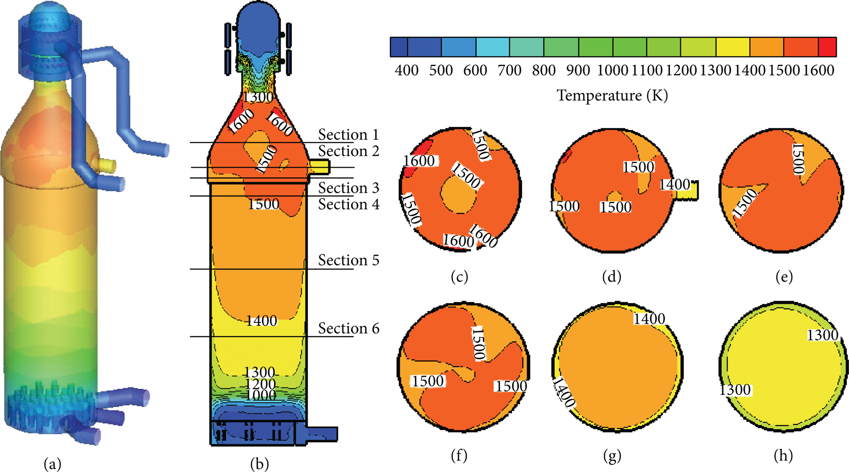
The temperature distribution of the traditional hot blast stove: (a) the temperature distribution on the wall; (b) the temperature distribution on the main section; (c)–(h) are the temperature distribution on sections (1)–(6), respectively.
On the other hand, a small local area of low temperature near the stove center can be found in the contour plot of section (1) (see also in Figure 6(c)). This is caused by the backflow structure inside the combustion chamber where velocity is almost stagnant. Furthermore, it can also be clearly seen that the internal temperature distribution is asymmetric in the combustion chamber. The temperature difference on the cross-section (1) is about 256 K. This nonuniform temperature distribution is caused by the eccentric swirling flow as discussed in previous section. As the flow goes down, as shown in Figures 6(d)–6(f), the unevenness of temperature distributions still persists but gradually diminished until it reaches lower part of the regenerator. Due to the high heat capacity of the regenerator, the temperature eventually becomes uniform before discharging from the flue pipe.
In theory, there could have been two main reasons contributed to the above eccentric swirling flow structure. The first reason could be due to the asymmetry of geometrical arrangement, while the other reason could be caused by the nonuniform velocity distribution in the stove. As the geometrical arrangement of the hot air stove is basically symmetric. We therefore postulated that the eccentric swirling flow is mainly attributed to the unevenness of the velocity distribution. Some interesting insights could be gained from the contour plots presented in Figures 7 and 8. Figure 7 shows the pressure distribution throughout the cavity ring at the second gas layer. As depicted, higher pressure value is found near the inlet as well as the opposite side of the ring. Other area within the ring is subject to lower pressure. As discharge velocity at the nozzle is mainly driven by the pressure difference, such pressure changes will cause substantial velocity variation at each nozzle.

The pressure distribution on cross-section of second layer gas nozzles.
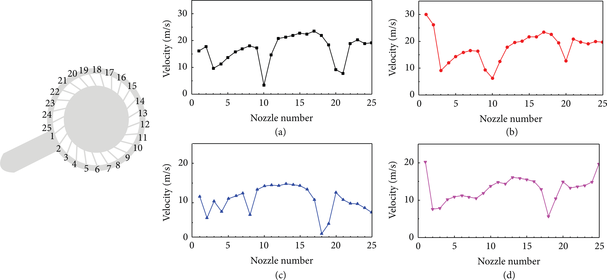
The velocity curve of the nozzles on each layer of traditional stove: (a) first layer, (b) second layer, (c) third layer, and (d) fourth layer.
This can be further ascertained by a closer examination of the velocity variation of each nozzle at all four layers (see Figure 8). For the ease of comparison, every nozzle at each layer is labelled in number as shown in Figure 8. As depicted, for all layers, significant velocity variations are found at each nozzle. At the first layer, the maximum velocity difference among nozzles is around 20 m/s. The imbalance of the discharging velocity will sequentially lead to the asymmetrical flow structure within the combustion chamber. In consequence, the resultant temperature distributions become nonuniform at the surface of regenerator.
3.4. Optimization of the Structure
To ensure the uniform pressure throughout the annular cavity ring, a series of design optimization studies have been carried aiming to investigate the influence of a set of design parameters, including the tangential inlet velocity, deflection angles, and number and arrangement of inlet pipes. In this paper, due to space limitation, design optimization is only focused on the arrangement of the inlet pipes.
3.4.1. Structure of the Novel Hot Blast Stove
As discussed in the previous sections, the fundamental problem of the current stove design is caused by the nonuniform pressure distribution throughout ring cavity. A novel hot blast stove is therefore proposed to have three inlet pipes for both fuel gas and air supply. These three inlet pipes for the fuel gas and air are evenly arranged along the circumference of the ring cavity (i.e., 120° apart from each other). Other than the pipe arrangement, the design of the rest of the hot blast stove is identical to the traditional one. Using the mathematical model presented before, the performance of the novel hot blast stove is then investigated. To refine the flow structure for the three inlet pipes, based on the grid sensitivity study, a grid independent mesh consists of 9.15 million nodes has been generated for the novel hot blast stove design.
3.4.2. Flow Field of the Novel Hot Blast Stove
Figure 9 shows the pressure distribution at the second gas nozzle layer. In comparison to the traditional design (see also Figure 7), one could easily notice that the pressure distribution becomes considerably more uniform. Further evidences can be also found in Figure 10 where velocity variations at every nozzle for all layers are shown. The maximum velocity difference among nozzles has reduced down to 5 m/s. Compared to the traditional design, we concluded that the velocity is more uniformly distributed in the novel hot blast stove. As a result, a more symmetric swirling flow structure is introduced within the furnace. Figure 11 shows the velocity vectors at the selected sections of the combustion chamber. Once again, the predicted results have shown that the flow field on the main section of chamber becomes more symmetric in the new proposed design. The induced vortex centers at each selected section are practical located at the center of the chamber.

The pressure distribution on cross-section of second layer gas nozzles of novel stove.

The velocity curve of the nozzles on each layer of novel stove: (a) first layer, (b) second layer, (c) third layer, and (d) fourth layer.

The velocity vector of novel stove. (a) The velocity vector on main section of the combustion chamber. (b)–(f) are velocity vectors on cross-sections (1)–(5), respectively.
3.4.3. Comparison of Mass Fraction of Species between the Traditional Stove and the Novel One
The uniform pressure and velocity distributions could also enhance the efficiency of the combustion processes. Figure 12 shows the predicted mass fraction of CO2 and O2 along the centerline of the traditional and the novel stove design. Here, the x-axis represents the height of the centerline plotting from the top surface of the stove, while the y-axis represents the predicted mass fraction of CO2 and O2. From predicted results, it can be observed that the mass fraction of CO2 in the combustion chamber of the proposed novel design is considerably higher than the traditional one. This clearly shows that more complete combustion has resulted in the new stove design and the performance of the combustion chamber has been also enhanced. As the chemical reaction continues in the regenerator, the fuel is almost completely consumed. The resultant mass fraction of CO2 and O2 in the two designs in the regenerator gradually becomes identical.
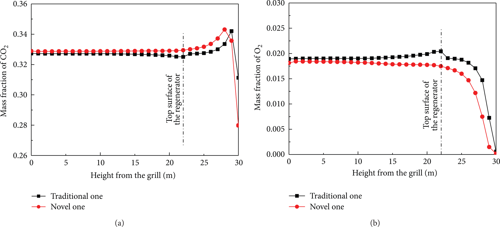
Comparison of mass fraction of species between the traditional stove and the novel one: (a) mass fraction of CO2 along the centerline of the traditional and the novel stove design; (b) mass fraction of O2 along the centerline of the traditional and the novel stove design.
3.4.4. Temperature Distribution of the Novel Hot Blast Stove
Figure 13 shows the predicted temperature distribution within the novel stove design. As depicted, the maximum temperature in the proposed hot blast stove design has raised to 1690 K (i.e., 40 K higher than the traditional design). Moreover, with the same heating time, more area is subjected to high temperature (i.e., higher than 1500 K) than the traditional design. This further ascertain that the novel hot blast stove could promote more efficient mixing between fuel gas and air and further enhance the performance of the combustion processes. In essence, based on the simulated results of air supply process, the novel hot blast stove can also obtain higher temperature than traditional design.

The temperature distribution of novel stove: (a) the temperature distribution on the wall; (b) the temperature distribution on the main section; (c)–(h) are the temperature distribution on sections (1)–(6), respectively.
It is worthwhile to notice that the predicted temperature contour becomes a saddle shape. This is caused by the strong rotational motion of the flue gas when it enters into the regenerator. Higher temperatures are found at the edges due to the higher convective heat transfer rate caused by the high rotating velocity. In contrast, at the center, the temperature is low due to the slower velocity with weakening convective heat transfer.
4. Conclusions
In the present work, a three-dimensional fluid flow heat transfer mathematical model coupled with combustion reaction model has been developed to study the combustion, gas flow, and heat transfer phenomenon of the hot air stove. Based on the predicted results, some findings have been obtained and summarized as follows.
In the combustion process, fuel gas is injected into the chamber and then mixed with the air. A swirling flow is formed due to the angel between the center line of the burner and the radial direction of precombustion chamber. Moreover, two main vortices are also found at the main section of combustion chamber.
An asymmetric swirling flow is found in the traditional hot air stove design which leads to a nonuniform temperature distribution in the regenerator.
A novel hot blast stove design is proposed and its performance was assessed and compared with traditional design using the developed numerical model. Based on the numerical investigation, the novel design is found to be able to establish more symmetric swirling flow as well as more uniform temperature distribution within the stove. The resultant highest temperature has also been raised around 40 K higher than the traditional design, suggesting that a better performance and more efficient combustion processes could be obtained with the novel hot blast stove design.
Conflict of Interests
The authors declare that there is no conflict of interests regarding the publication of this paper.
Footnotes
Nomenclature
Acknowledgment
This study was supported by the Fundamental Research Funds for the Central Universities (N130402013).