
Abstract
This study investigates a method of designing a simplified cylindrical shell model. This model accurately predicts the dynamic characteristics of a prototype cylindrical shell with sealing teeth accurately. The significance of this study is that it provides an acceptable process which guides the design of test models. Firstly, an equivalent cylindrical shell with rectangular rings is designed by combining the energy equation and numerical analysis. Then the transfer matrixes of the stiffened cylindrical shell and the cylindrical shell are employed to calculate the equivalent thickness of the simplified cylindrical shell commonly used in model tests. Further, the equivalent thicknesses are normalized by introducing an average equivalent thickness. The distorted scaling laws and size applicable intervals are investigated to reduce the errors caused by the normalization. Finally, a 42CrMo cylindrical shell with sealing teeth is used as a prototype and a number 45 steel scaled-down cylindrical shell is used as a distorted test model. The accuracy of the prediction is verified by using experimental data, and the results indicate that the distorted model can predict the characteristics of the stiffened cylindrical shell prototype with good accuracy.
1. Introduction
A cylindrical shell with sealing teeth is a type of cylindrical structure widely applied in engineering, such as in advanced gas turbines, high-powered aircraft jet engines, and high-speed centrifugal separators [1].
Vibration problems are one of the most significant contents in analyzing the cylindrical shell structure [2]. However, the experimental tests of the actual structure are costly and time-consuming. Consequently, a dynamic similarity scaled-down model is used to predict the behavior of the prototype. However, due to the lack of availability of materials, or the unavailability of specified dimensions of members, it has become necessary to adopt two or more different length scales, and this leads to distortion of geometry.
Scaling laws of cylindrical shell structures have been the subject of many investigations. Ramu et al. [3] investigated the scaling law for the free vibration response of structures along with different materials. Similarity conditions were established based on dimensional analysis, and their use in the scaled model was presented. Qian et al. [4, 5] used governing equations to establish the scaling laws of the impulse response of laminated plates. The results indicated that scaling laws could predict the undamaged response to impact accurately. The results were found to follow the scaling rules closely when the plate dimensions, projectile dimensions, and impact parameters are varied. Ungbhakorn and Singhatanadgid [6, 7] established the scaling laws of antisymmetric cross-ply and angle-ply isotropic laminated plates by directly applying the governing equations of buckling and frequency. Partial similitude was considered and the scaling laws which yield good agreement were recommended. Ungbhakorn et al. [8, 9] derived the scaling laws of symmetric and antisymmetric cross-ply laminated circular cylindrical shells by using the governing equations. Both complete and partial similitude cases are investigated in predicting the vibration and buckling problems. Rezaeepazhand et al. [10, 11] have studied the scaling laws of distortion models for predicting laminate shell buckling and free vibration. In their studies, the scaling laws of different material properties, the number of plies, and geometric size were derived by using the governing equations of laminated plates and shells.
In the study of Oshiro and Alves [12, 13], a new scaling law of the impacted strain-rate sensitive structures was discussed. A robust correction procedure and the indirect similitude method are studied. Oshiro and Alves [14, 15] predicted the prototype behavior by changing impact velocities, and a new scaling law was presented by introducing an exponential constitutive law. In addition, the transition model was used to find the value of parameters in the scaling law. Cho et al. [16] realized that the requirement of identical dimensionless parameters inherent in the traditional similarity method is often impossible to satisfy. An empirical similarity method was developed by analyzing the specimen pair and the method was used to correlate scale models with distorted configurations.
There are not many research studies on the similitude design of the stiffened cylindrical shell. Torkamani et al. [17] developed the scaling laws for free vibrations of orthogonally stiffened cylindrical shells by using the similitude theory in which the stiffened rings are simplified as T-style rings. This work is valuable but needs further investigation such as for the thin-wall cylindrical shells that are commonly used in model tests.
In the present study, the problem associated with the dynamic similarity scaled-down models of cylindrical shells with sealing teeth is discussed. An equivalent cylindrical shell with rectangular rings is designed in order to calculate the transfer matrix. Further, the method of using the transfer matrix and similitude theory are combined to design the cylindrical shell model. Numerical analysis and experimental tests are used to verify the accuracy of the design method.
2. Equivalent Design of Cylindrical Shell with Sealing Teeth
2.1. Energy Equations
Cylindrical shells are widely used in aeroengines. Figure 1 shows the cylindrical shell with sealing teeth. In cylindrical coordinate system o′x′θ′r, origin o′ is the center point on one of the end faces of cylindrical shell, where the x′-axis and the center line overlap. θ′ is the deflection angle and r is the length of the radial coordinate.
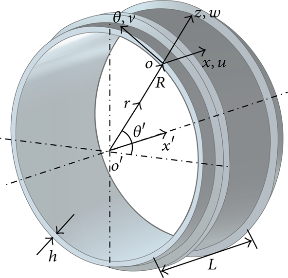
A cylindrical shell with sealing teeth.
The orthogonal coordinate system oxθz is determined by translating the coordinate system o′x′θ′r with a distance R from origin o′ along the r-direction to o. R is the radius of the middle surface. The x-axis and the x′-axis are parallel. The θ-axis and the θ′-axis overlap and are in the same tangent direction of the shell surface. The z-axis and the r-axis are overlapping. h is the thickness of the cylinder shell; L is the length of the cylinder shell. u(x, θ, t), v(x, θ, t), and w(x, θ, t) represent the displacement of x, θ, and z directions, respectively. Young's modulus, Poisson's ratio, and the density of the shell's material are denoted by E, μ, and ρ, respectively.
According to the Love theory, the energy equation of a sealing tooth is written as [18]
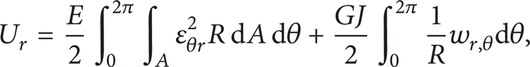
where ∊θr is the circumferential strain of the sealing tooth, ∊θr = (1/R)(v,θ − (z/R)w,θθ + w); subscripts (,θ) and (, θθ) represent the first and the second differentiation for θ, respectively; A is the cross-section of the sealing tooth; G is the shear modulus; J is the moment of inertia about the vertical axis through centroid; and GJ represents the torsional stiffness of the sealing tooth.
2.2. Equivalent Design Method of Sealing Teeth
As the dynamic characteristics of cylindrical shells with sealing teeth are hard to calculate and there are no common equations to describe these problems, an equivalent design method is studied to simplify the structure of the cylindrical shell with sealing teeth with the aim of making the investigation easier.
According to (1), the energy equation is unfolded and the following equation is obtained:

In (2),

where Z is the centrifugal distance from the middle surface of the shell to the centroid of the tooth.
In order to use rectangular rings replacing the sealing teeth, the following equations should be satisfied:

where subscript s represents the sealing tooth and subscript r represents the rectangular ring.
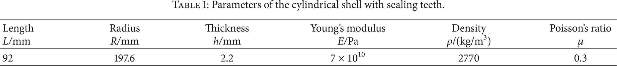
Parameters of the cylindrical shell with sealing teeth are shown in Table 1. Figure 2 shows the details of the sealing teeth. The three sealing teeth in Figure 3 are marked as numbers 1, 2, and 3. The lengths of the hemlines are bs1 = bs2 = bs3 = 2 mm, the heights of the sealing teeth are as1 = as2 = as3 = 5 mm, and the distances between each tooth are Ls1 = 10 mm, Ls2 = 57 mm, and Ls3 = 3 mm. The material of the shell is aluminium alloy.
Parameters of the cylindrical shell with sealing teeth.

Details of sealing teeth.

The equivalent rectangular rings.
In Figure 2, as number 2 and number 3 teeth are close to each other, they are considered to be replaced by a single rectangular ring, and number 1 tooth is replaced by another rectangular ring (Figure 3), where Lr2 = Ls2 + Ls3/2, Lr1 = Ls1.
A clamped-free (C-F) boundary condition is satisfied in the present study. Edge A* in Figures 2 and 3 is clamped and edge B* is free. Substituting cross-sectional area A, the centrifugal distance Z, the moment of inertia about the horizontal axis through centroid I, and the moment of inertia about the vertical axis through centroid J into (4) yields
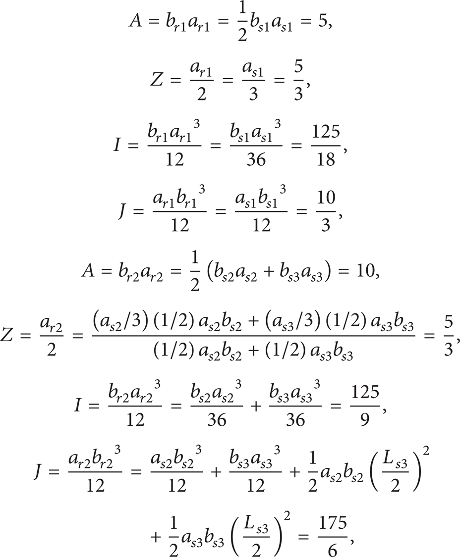
where a ri and b ri are the height and width of number i rectangular ring and a si and b si are the height and width of number i sealing tooth, respectively.
However, in (5), two variables are determined by four equations; thus it is impossible to obtain values of a r and b r that satisfy all the equations. In this case, two different methods are discussed to obtain acceptable a r and b r . One is to use the least square method. The other is to neglect two of the equations to obtain the exact solutions. Table 2 shows different values of a r and b r obtained by the two methods.
a r and b r obtained in different conditions.

The errors of natural frequencies in different orders that correlate to different methods are shown in Figure 4. The abscissa of Figure 4 is arranged by the circumference wave number, from n = 3 to n = 10 in the previous 8 orders.

Errors of natural frequencies of different equivalent values of a r and b r .
From Figure 4, the following conclusions can be obtained. (1) The equation set A s = A r , Z s = Z r shows the most accurate results among these seven equation sets, which indicates that conditions I s = I r and J s = J r have slight influence on the natural frequencies of the stiffened cylindrical shell. (2) The error of the equivalent design increases as the circumference wave number increases. Table 3 shows more details about the least square method and the A s = A r , Z s = Z r method. Errors between the cylindrical shell with sealing teeth and the cylindrical shell with rectangular rings are represented by η r :

Comparision between sealing teeth and rectangular rings.
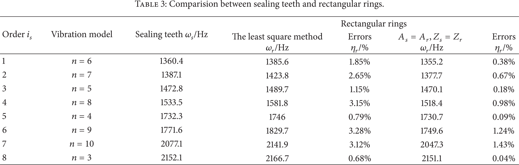
Table 3 indicates that both the least square method and selection of A s = A r , Z s = Z r are applicable in the equivalent design. Although the least square method is widely used in engineering practice, as the moment of inertia I and the moment of inertia J have a slight effect on the natural frequencies of cylindrical shell with sealing teeth, A s = A r , Z s = Z r is more acceptable in the present study.
3. Simplified Design of the Cylindrical Shell with Rectangular Rings
Cylindrical shells are commonly used in model test. Though the sealing teeth of the cylindrical shell are equivalent by rectangular rings, it is still significant to simplify the structure into a cylindrical shell. Therefore, an equivalent cylindrical shell is investigated to match the stiffened shell. Different equivalent thicknesses and average equivalent thicknesses are designed by employing a transfer matrix [19] and similitude theory.
3.1. Governing Equations
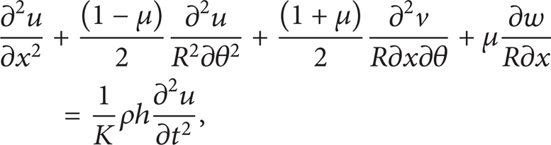
For the sake of analyzing the stiffened cylindrical shell, a cylindrical shell element should be considered first. Kirchhoff-Love hypothesis and the Love shell theory are employed in analyzing the linear vibration of the cylindrical shell, and the following governing equations are obtained by using the Hamilton theory [20]:

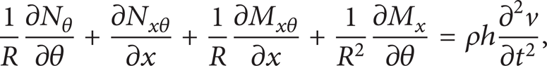
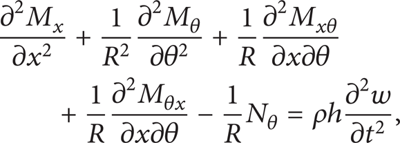
where R is the radius of cylindrical shell. h is the thickness of cylindrical shell. ρh(∂2u/∂t2), ρh(∂2v/∂t2), and ρh(∂2w/∂t2) are inertia items; N x , Nθ, and Nxθ are in-plane stress resultants; M x , Mθ, and Mxθ are bending and twisting stress resultants:

where K is the extensional rigidity, K = Eh/(1 − μ2); D is the flexural rigidity, D = Eh3/12(1 − μ2); ∊ x (0), ∊θ(0) are the membrane strains, ∊ x (0) = ∂u/∂x, ∊θ(0) = ∂v/R∂θ + w/R; γxθ(0) is the bending strain, γxθ(0) = ∂v/∂x + ∂u/R∂θ; and κ x , κθ, and χxθ are the change-in-curvature terms, κ x = − ∂2w/∂x2, κθ = (1/R2)[∂v/∂θ − ∂2w/∂θ2], and χxθ = ∂v/R∂x − 2(∂2w/R∂θ∂x).
Three extra parameters are introduced based on the Kirchhoff hypothesis: in-plane shear force V x , transverse shear force S x , and the rotation about θ axis ϕ x :


where Q x is the transverse shear force resultant along the x direction, Q x = ∂M x /∂x + ∂Mxθ/R∂θ.
3.2. Simplified Design Based on Transfer Matrix
3.2.1. Transfer Matrix of the Cylindrical Shell with Rectangular Rings
According to (7a), (7b), and (7c) and (9a), (9b), and (9c), there are eight equations and eight variables. Form these eight variables as a vector:

Substituting (10) into (7a), (7b), and (7c) and (9a), (9b), and (9c) yields

where
The displacement functions and corresponding stress resultants, when vibrating with a circumferential wave number n, are assumed as follows:

where m is the axial wave number, m = 1.
Substituting (12) into (11) yields

where

There are five main sections in the stiffened shell shown in Figure 5(a) represented by
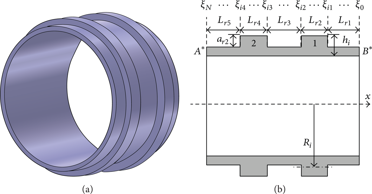
The cylindrical shell with rectangular rings and the divided sections. (a) Cylindrical shell with rectangular rings and (b) characteristics of shell sections.
Considering the equation

where
According to (15), the equation of the kth subsection can be written as

where L
k
is the length of the kth cylindrical shell element and
Therefore the following equation can be obtained:

where
3.2.2. Simplified Method
To study the simplified method of the stiffened cylindrical shell, the method of calculating transfer matrix should be considered (Appendix B).
However, to solve the exact result of the natural frequencies, the value of N′ shown in Appendix B has to be large enough, which makes the calculation time-consuming. Therefore, in the present paper, N′ = 3 is used to obtain approximate results in the simplified design process [22], which is proved acceptable in designing the equivalent thickness.
According to Figure 6 and Appendix B, the transfer matrix of the cylindrical shell with rectangular rings can be written as

where
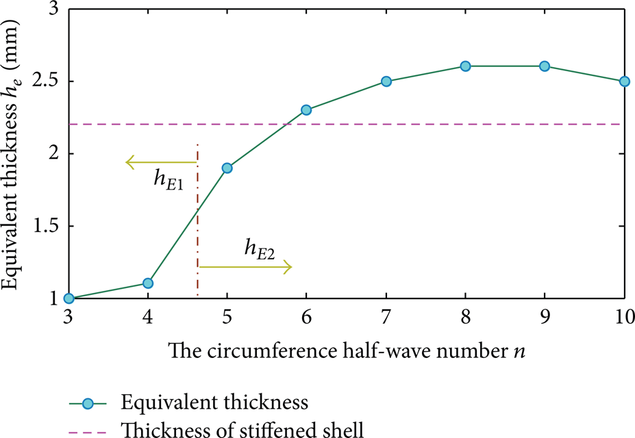
Equivalent thickness of each order.
The approximate frequencies ω ap can be obtained by following the process in Appendix B; ω ap can be represented as

where
Substituting (19) into the transfer matrix of the cylindrical shell, in which thickness h is a variable and other parameters of the cylindrical shell are the same as those of the stiffened shell,

where h e is the equivalent thickness.
Therefore, with the same process of solving frequencies, the equivalent thickness is obtained.
Considering the cylinder shell with rectangular rings designed in Section 2, the resulting parameters are shown in Table 4.
Parameters of the cylindrical shell with rectangular rings.

The equivalent thicknesses of the previous eight orders' natural frequencies are calculated and ANSYS simulation is employed to verify the applicability of the equivalent thickness (Table 5):

The equivalent thickness and errors of the equivalent shell.

From Table 5, the simplified method of designing the equivalent thickness shows an applicable result. However, in practical situation, it is complex to manufacture different cylindrical shells for each order of the stiffened shell. The changing trend of the equivalent thickness is shown in Figure 6.
In Figure 6, the equivalent thicknesses are divided into two groups. It is considerable because when h e ≈ 1 mm, n ≤ 4 matches high-order vibrations; when h e ∈ [1.9, 2.6], n ∈ [5, 10] matches low-order vibrations (previous eight orders).
Thus two average equivalent thicknesses are defined:
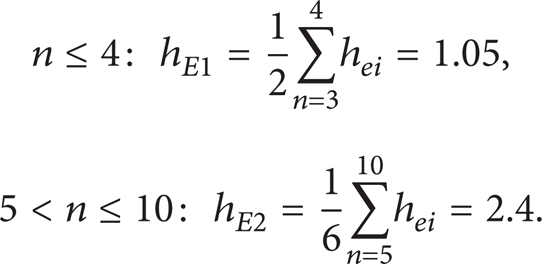
Figure 7 indicates that cylindrical shells with various thicknesses are required in a model test. However, it is more practical to use fewer model cylindrical shells in a predicting test. Therefore, hE1 = 1 mm, hE2 = 2.4 mm are selected. Obviously, the average equivalent thickness, especially hE2, may cause unacceptable errors in predicting the dynamic characteristics of the cylindrical shell with sealing teeth, and these low-order vibrations have typically occurred in model tests. However, these errors would be reduced by the distorted scaling law and the size applicable intervals [23] (see Section 4).

Verification of fourth-order polynomial fitting results.
4. Design of a Distorted Model
4.1. The Distorted Scaling Law of the Cylindrical Shell
Equations (7a), (7b), and (7c) show the governing equations of the cylindrical shell. Substituting (8) into (7a), (7b), and (7c) yields


where ∇ is the Laplace operator, ∇2 = ∂2/∂x2 + ∂2/R2∂θ2, and
λβ is used to represent scaling laws, λβ = β M /β P ; subscripts M and P represent model and prototype, respectively. β represents the symbol of each physical quality; for example, β = a, b, E, and so forth.
In distorted similitude condition (λ h , λ R , λ L are not equal simultaneously), assuming λ L = Cλ R . According to the previous studies of the authors, the distorted scaling law can be written as [24]

In the present study, C = 1 is required. Assuming Ξ = λ h /λ, the scaling law can be rewritten as

4.2. The Determination of Size Applicable Intervals
The parameters of cylindrical shell with average equivalent thickness and distorted models are shown in Table 6. According to Table 5, the range of Ξ chosen to analyse is Ξ ∈ [0.8, 1.33], which means h e ∈ [1.8, 3] mm.
Parameters of the equivalent cylindrical shell.

Choose different scaled models with parameter Ξ = [0.8, 0.86, 0.92, 1.0, 1.09, 1.2, 1.33]; the prediction values of the first-order natural frequency (n = 7) are represented by ω pr 1. Fitting the 6 discrete predictive values by 4-order polynomial in MATLAB yields the predictive equation
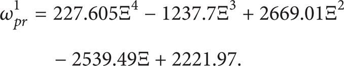
Select more discrete values with the step size for 0.05 to verify the applicability of (26). See Figure 7.
Figure 7 shows that, in the range of Ξ ∈ [0.8, 1.33], (26) has the accurate fitting effect. The error of the prediction is

Considering the predictive error of the first order is very small, let η pr ≤ 5%. Substituting (24) into (27) yields

By solving (28) in the range of Ξ ∈ [0.8, 1.33], get Ξmin = 0.63, Ξmax = 1.58. Ξmin , Ξmax are the boundary values of the acceptable intervals. Table 7 shows the size applicable intervals of the previous six orders.
Size applicable intervals of cylindrical shell.
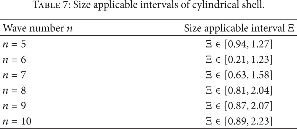
According to Tables 5 and 7 equivalent thickness of each order is contained by the matching size applicable interval. So the average equivalent thickness hE2 is acceptable.
Consider the prototype cylindrical shell with rectangular rings shown in Table 4 and the model equivalent cylindrical shell shown in Table 6 with λ = 2 and hE2m = 1.2 mm.
The natural frequencies of different orders are compared in Table 8; ηave is the error of predictive values.
Prediction of stiffened cylindrical shell.

5. Experimental Verification
According to the discussion in the above sections, an equivalent distorted scaled model of the cylindrical shell with sealing teeth is designed and the method of reducing the predicted errors is investigated. To be clearer, the process of the simplified design is shown in Figure 8.
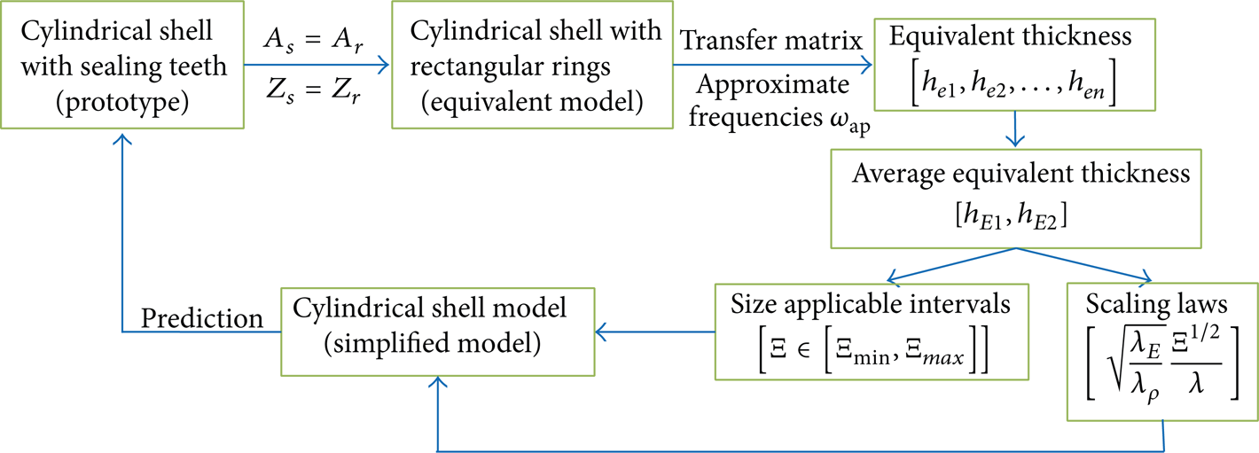
The process of the simplified design.
Experimental data are used to verify the method presented in this study. The parameters of prototype and model thin-wall short cylinder shell are shown in Table 9.
Structure and material parameters of experimental prototype and model.

Figure 9 shows the experimental cylindrical shell. LMS system is chosen as the equipment of the test. Table 10 shows the errors of prediction of the n = 5~9 orders. Figures 10 and 11 show the vibration modes of the prototype and the model.
Predicted errors of cylindrical shell.

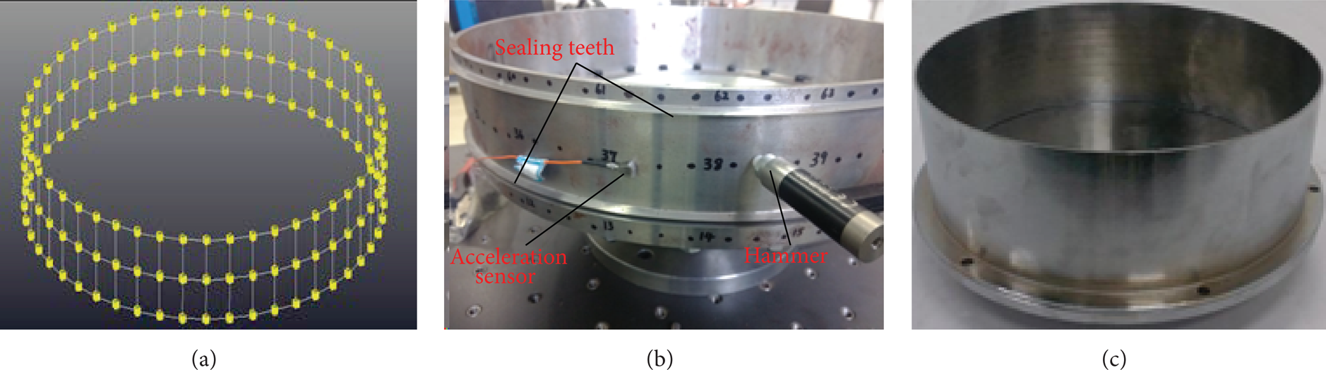
Experimental cylindrical shells. (a) Geometric model in LMS, (b) prototype of cylindrical shell, and (c) distorted model.

Vibration models of the cylindrical shell with sealing teeth. (a) n = 5, 3rd order, (b) n = 6, 1st order, (c) n = 7, 2nd order, (d) n = 8, 4th order, and (e) n = 9, 5th order.

Vibration models of the cylindrical shell model. (a) n = 5, 4th order, (b) n = 6, 2nd order, (c) n = 7, 1st order, (d) n = 8, 3rd order, and (e) n = 9, 6th order.
Table 10 indicates that the simplified cylindrical can predict the natural frequencies of the prototype cylindrical shell with sealing teeth in a good accuracy. However, the vibration models cannot match in each order under this method.
6. Conclusions
This study presents the design method of a distorted cylindrical shell test model in predicting dynamic characteristics of cylindrical shell with sealing teeth. The equivalent cylindrical shell with rectangular rings is designed in order to calculate the average equivalent thickness. Distorted scaling law and size applicable intervals are also employed to reduce the predictive errors caused by simplified design.
The results presented herein indicate that the dynamic characteristics of the cylindrical shell with sealing teeth can be accurately predicted by a distorted simplified model. Specific conclusions are listed as follows.
The equivalent cylindrical shell with rectangular rings is designed by satisfying the condition of A s = A r , Z s = Z r , which is selected by using the numerical analysis method. The moments of inertia, I and J, have slight influence on the natural frequencies of the stiffened cylindrical shell; thus the least square method and other conditions are not suitable in this case.
The transfer matrix method is employed to calculate equivalent thicknesses of the simplified cylindrical shell. An approximate frequency ω ap is introduced with N′ = 3 in solving the transfer matrixes. This method shows an acceptable result in designing the equivalent thickness.
The equivalent thicknesses are divided into two groups: low order and high order. Only low-order vibration is considered as the equivalent thicknesses of the high-order vibration are almost the same, and the method used in low-order vibrations is also applicable in high-order vibrations.
An average equivalent thickness hE2 is presented in this study. Distorted scaling law
The process of designing the simplified cylindrical model is shown in Figure 8. Experiment is employed to verify the method presented in this study. The natural frequencies of cylindrical shell with sealing teeth are predicted by a small scaled cylindrical shell. The prediction error of n = 5 is larger than those of other vibration orders.
Conflict of Interests
The authors declare that they have no conflict of interests, including specific financial interests and relationships relevant to the subject of this paper.
Footnotes
Appendices
Acknowledgments
This work was supported by the National Science Foundation of China (Grant no. 51105064); the Fundamental Research Funds for the Central Universities of China (Grant no. N1305030011); and the National Program on Key Basic Research Project (Grant no. 2012CB026000).