
Abstract
The simulation of advanced high-strength steel sheet (AHSS) stamping processes by means of dedicated computer-aided engineering (CAE) software requires the use of appropriate material models, the use of complex FEM models, and the use of advanced methods for solving nonlinear problems of their analysis. In practice, the engineering design of automotive body parts often leads to the formulation of problems, the solution of which requires ample computer resources and is very time-consuming. The paper describes a methodology to simulate stamping on the example of a car body part, with special attention being paid to the numerical efficiency of the FEM model and methods of solving it. The simulations of stamping of a sample stamped part—the automotive body part—in DynaForm and AutoForm programs are compared, focusing on the numerical effectiveness and consistency of the simulation results with the reality.
1. Introduction
The recent progress in car body design and manufacturing technology has caused the need for the use of stamped parts made of advanced/ultra-high-strength steel (AHSS) on car body parts. These steels, however, create new problems in the design of stamped parts and dies. One of them is the spring-back effect caused by the relaxation of the elastic part of strains caused by stamping after unload. Stamped parts made of AHSS have a greater spring-back effect than those made of the commonly used structural steel for plastic working. On the other hand, designers have better and better tools for computer-aided design and analysis that allow for more and more accurate simulation of the stamping process, along with determination of a spring-back value. However, in order to carry out the simulation in the right way, it is necessary to properly define the tasks and get appropriate data for the calculations. Then, with the help of tools available in a program, one can adjust the initial shape of parts of the die such as draw punch, die faces, and blank-holders, so that the shape and dimensions of the stamped part are in compliance with the project requirements. The remainder of this paper describes the process of modelling a sample stamped part, a car body part, using specialized software programs, DynaForm and AutoForm, dedicated to the design and simulation of metal sheet stamping with the ability to compensate the spring-back effect of a stamped part, paying attention to the numerical effectiveness of the model and methods of solutions, software.
2. The Material Model of a Stamped Part
The starting point for the analysis is the correct material model, including appropriate plastic yield condition and the flow rule. Among many models for anisotropic materials for plane stress and strain described in the literature, three of them are most commonly used in practice:
Hill [1],
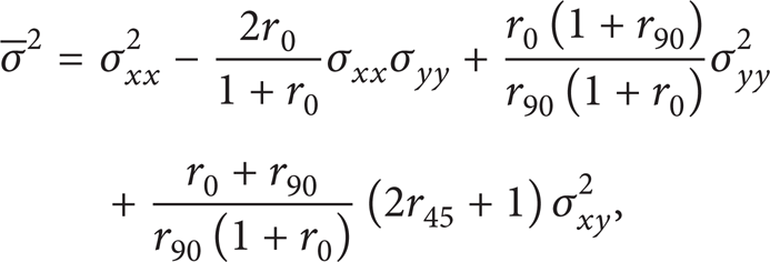
where r0, r45, r90 are Lankford coefficients characterizing anisotropy, oriented towards the direction of rolling, determined in a uniaxial stretching test,
Barlat and Lian [2],

where

where σ0 is a yield strength at bidirectional stretching at σ xx = σ yy and σ p is a yield strength at unidirectional stretching and M = 6 for steel,
Banabic et al. [3],

where

where constants K, L, N, P, Q, R, S, and T are experimental material parameters determining the shape of plasticizing surface and M = 6 for steel.
During bending and unbending of the metal sheet, certain phenomena occur in its material, which affect the final result of shape forming during stamping (Figure 1). These are [4]
Bauschinger effect (a), in which the material, initially in a soft state, has the same yield strength σ0 at stretching and pressing, and after loading (stretching) with strain σ > σ0 it gets stronger, but as a result of unloading and pressing it gets plasticized at a strain of σ > σ0,
the effect of transition from elastic to plastic state (b), in which there is a smooth, yet abrupt, change in the curve of characteristics σ(∊ p ) at another loading,
the hardening effect (c), which is the result of dislocation of plastic flow surface towards plastic deformation, which causes a permanent slope of characteristics σ(∊ p ),
the effect of final weakening (d), which is caused by an offset of characteristics σ(∊ p ) after another loading.
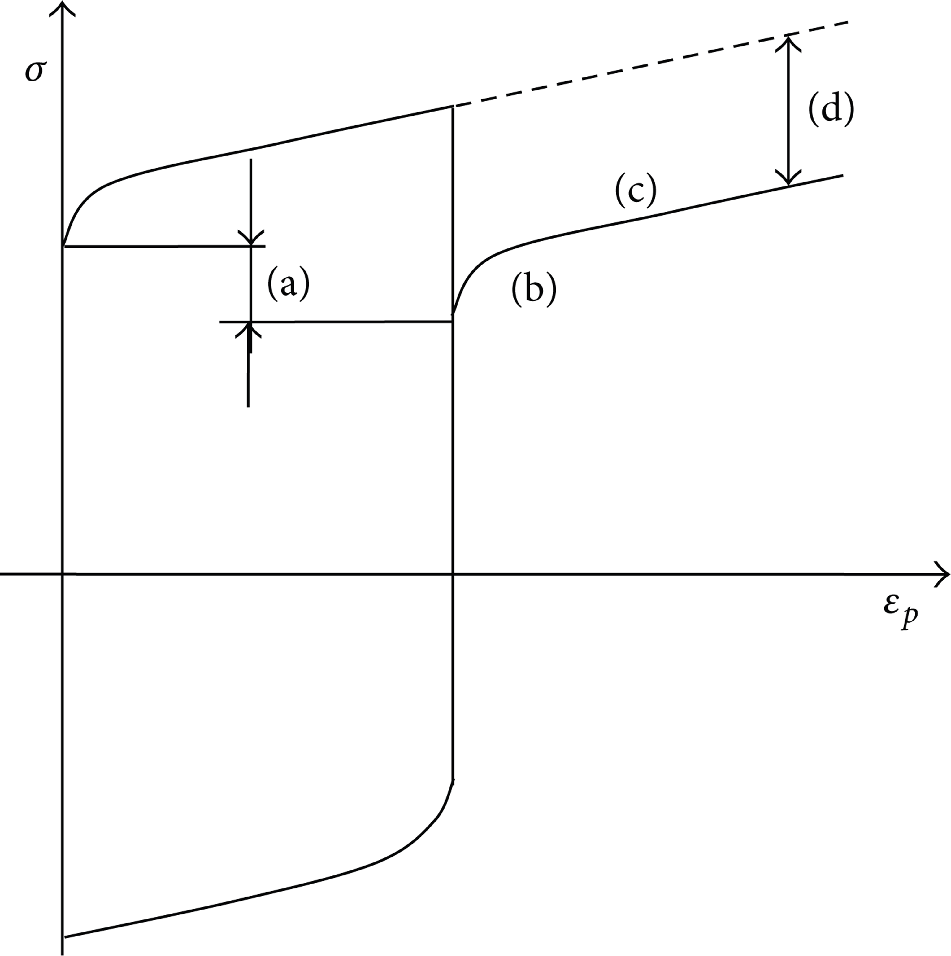
Diagram of effects in material during bending and unbending.
These effects of phenomena occurring in the material during the cyclic plastic deformation to varying degrees affect the accuracy of the simulation of the stamping process. Their inclusion requires the adoption of an appropriate hardening hypothesis, which, depending on assumptions and the related complexity of the constitutive equation, is more or less suitable in engineering applications. The most commonly used include
the hypothesis of mixed hardening [5], which takes into account both the isotropic and kinematic hardening while their proportions are determined by a weighting factor, and consequently the Bauschinger effect (a) and the effect of final weakening (d) (Figure 1) are taken into account,
Armstrong-Frederick hypothesis of hardening [6], which takes into account Bauschinger effect (a) and the effect of transition from elastic to plastic state (b) (Figure 1),
Geng-Wagoner hypothesis of hardening [7], which is the extension of the previous hypothesis and additionally it takes into account the hardening effect (c) (Figure 1),
Yoshida-Uemori hypothesis of hardening [8], which includes all the previously mentioned effects of changes in the material (a), (b), (c), and (d) (Figure 1).
The method of experimental determination of the material parameters present in the constitutive equations of plasticity conditions and hardening hypotheses and their values for selected AHSS steels are given in [4].
3. The Geometrical Model and FEM Model of a Stamped Part
Dedicated programs aiding in the design of stamped parts and dies, most widely used in the automotive industry, are, among others, DynaForm, AutoForm, and PamStamp. To design a die, taking into account the stamped part spring-back compensation, one must first make its geometric model. This should be a surface model. It can be made in any 3D CAD environment, for example, CATIA system. As the stamped part is usually formed in several successive steps, the one followed by the strongest (critical) spring-back effect has been selected for the purpose of further analysis. Figure 2 presents the postulated shape of the sample stamped part after this step.

Geometrical model of stamped part with marked section planes.
In the next step, models of contact surfaces of parts of die are formed, that is, the draw punch, die face, and the blank-holder with the stamped part, by using the offset function available in CAD software. The value of offset results from the thickness of the stamped sheet, out of which a blank is cut. The contour of the resulting blank allows for stamping with the least possible waste.
The next part of the stamped part modelling and stamping simulation is presented on the example of DynaForm; however, these processes are similar in other programs of this type (e.g., AutoForm). The program can import geometric models of the blank and part of the die (Figure 3) from the CAD system. Stamping simulation requires creating FEM models of the draw punch, die face, and the blank. Obviously, the most important model is that of the blank/stamped part, which has been discretized by means of SHELL16 surface elements. These are 4-node elements with square shape functions which provide a reasonable compromise between the adequacy of the model (giving results consistent with reality) and the numerical efficiency of the model (requiring moderate computer resources and computation time) for simulating large elastic-plastic deformations during bending. Correct discretization requires an experienced user and the rules of good practice [9]. The mesh of nodes should be regular and concentrated in fillets, holes, and similar places where the curvature changes drastically.
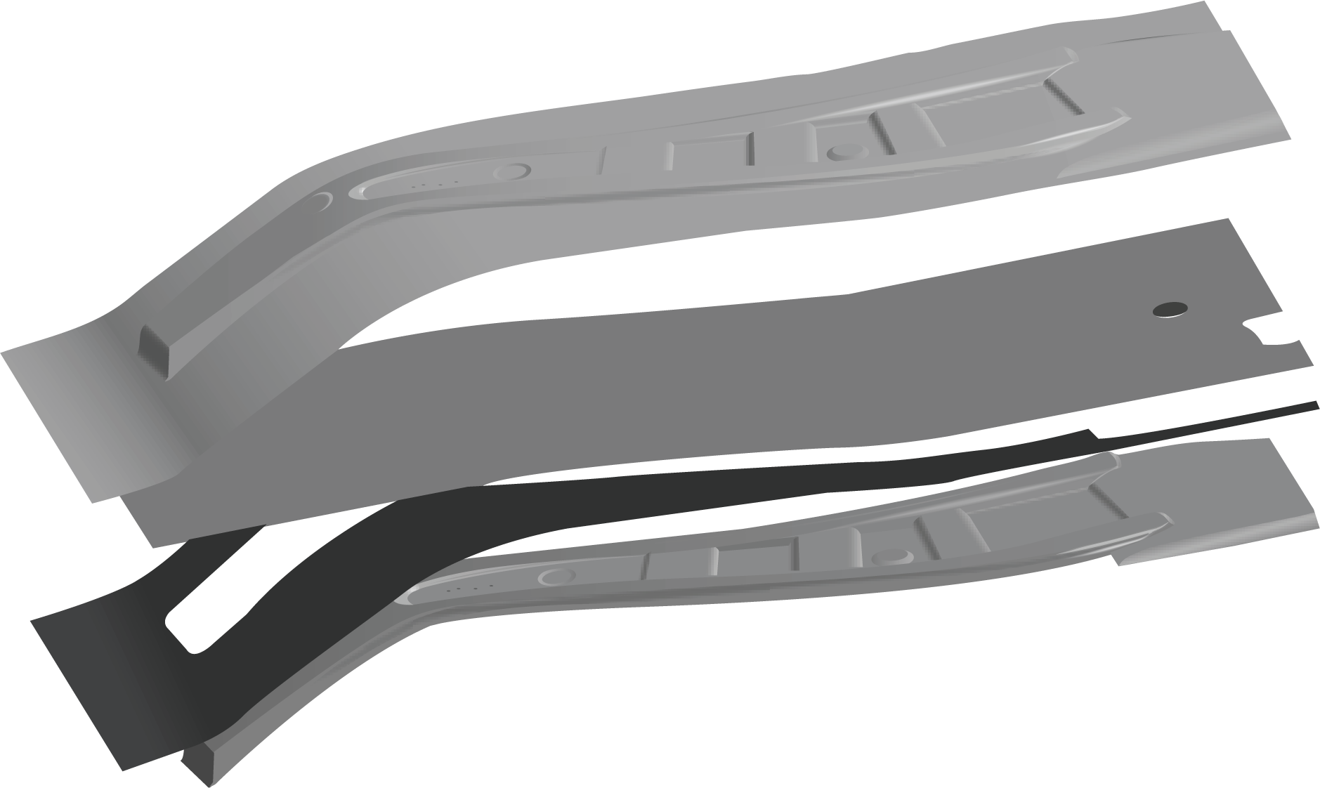
Geometric models of draw punch, die face, blank-holder, and blank.
The blank has been made of steel HSLA420, for which Barlat-Lian model and the hardening hypothesis of Yoshida-Uemori have been applied. The following numerical values have been set in the calculations E = 207 GPa, ν = 0,28, and r0 = r90 = 1, 0; the anisotropy parameter p has been calculated iteratively using the Krupskowsky law σ = k(∊0 + ∊) n , k = 1260 MPa, ∊0 = − 0.235064, and n = 0.135. During the simulation, the parts of the die (blank-holder, draw punch, and die face) are treated as rigid bodies, which occurs after assigning material type 20 to them (rigid material). As a result, the program treats the SHELL element as a rigid element, wherein the elements having the same label (ID) are automatically combined into a single rigid body, the position of which is defined by six degrees of freedom. Material constants (Young's modulus E and Poisson ratio ν) assigned to material type 20 do not make it an elastic body, but they are used in defining the parameters of the contact elements for modelling the contact point between the blank and the tools. The impact of the draw punch and the die face on the blank is modelled using nonlinear contact elements type 4 (surface-to-surface) that the program generates automatically.
4. Determining the Spring-Back
The purpose of the analysis is to simulate stamping and determine the value of the stamped part spring-back. Solving this last task allows adjusting the predesigned working surfaces of the die so as to compensate this spring-back. Naturally, the quality of the stamped part has to meet construction requirements and, in particular, the stamped part cannot have cracks, excessive thinning, or wrinkling.
Let us assume [10] that the shape of the working surface of the die is denoted by N, an element vector of nodal coordinates

where | | is the Euclidean norm.
For optimal solution
As noted earlier, due to the nature of the simulation, during which optimization problem (6) is solved, the problem of the numerical efficiency of the FEM models in the task and solution methods (solvers), and more precisely the demand for operational memory and CPU time, is a critical issue here.
5. The Analysis of Numerical Effectiveness
5.1. The FEM Model of a Stamped Part
The numerical effectiveness of the FEM model of a stamped part can be improved as long as the number of the finite elements/nodes of the FEM model of the blank is reduced without a significant deterioration of the quality of the solution. Programs for simulating metal sheet stamping, including LS-Dyna, have a special procedure for this purpose that makes it possible to consolidate multiple adjacent finite elements into one, mesh coarsening. In order not to compromise the quality of solutions, areas of the model that will not be subject to large deformations, such as plane areas, are selected. The parameter of the procedure is flatness tolerance (angle) expressed by the angle between the normal and the finite elements. Elements whose normal is within the specified tolerance are treated as lying on the same plane and then consolidated in one piece (Figure 4). Up to eight nodes of the model can be specified, around which the consolidation is to take place (of course, they cannot lie on the edges or in places where the boundary conditions are defined).
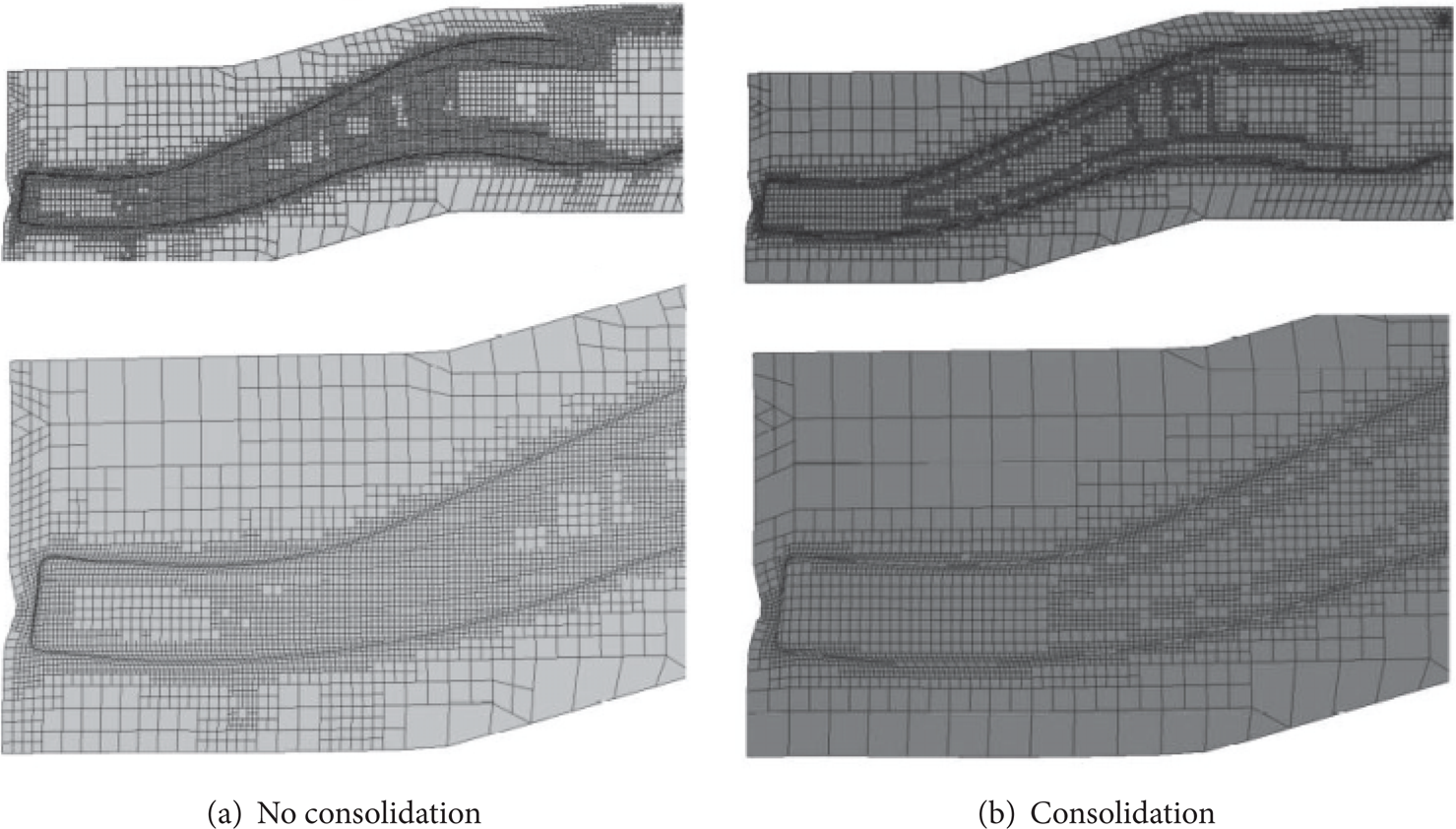
FEM model of the stamped part: without the consolidation of elements (a) and with the consolidation of elements (b).
As a result of the consolidation of the elements of the FEM model of the analysed stamped part, their number decreased from 18,301 to 11,620, that is, by 37%, while the number of nodes decreased from 19,283 to 13,212, that is, by 31%. To study the impact of the consolidation of elements on the numerical effectiveness of the FEM model, the effect of the stamped part spring-back of both models was analysed, before and after consolidation was made. The computation time decreased from 34 to 25 seconds (the calculations were performed on a computer with an Intel i7, 3.2 GHz and 16 GB of RAM, involving four processor cores simultaneously), by 26%. The improvement of the numerical effectiveness of the FEM model, the measure of which is the reduction of the computation time, depends primarily on the shape of a stamped part; if it is irregular with a small amount of plane regions, it will decrease, and otherwise it will increase.
5.2. Solution Methods
Despite the reduction of the number of the FEM model elements of the stamped part by the consolidation of elements, their number in FEM models of stamped parts used in car industry is calculated in thousands or even more, as a result of which a time of analysis is far too long for the engineering practice.
(i) To improve the numerical effectiveness of task solving in programs for simulating metal sheet stamping, for example, DynaForm, the standard shape functions of finite elements are replaced with functions, which are forms of free vibrations, eigenvectors of the task FEM model expressed with the global coordinates of the model. The advantage of such a procedure is that their own shapes are determined only once and can be used in subsequent iterations of problem solving and that it avoids transformation of local coordinate systems associated with the finite elements to the global coordinates of the model. A suitable vibration equation for a discrete model can generally be written as follows:

where [
where
Since the task to be solved is a static task, in (8) the mass matrix can be substituted with an identity matrix [
The eigenvectors of task (9) will be the base for the shape function in the task. The working surfaces of the die and the blank after deformation, stamped part, will be interpolated as if the surface nodes before deformation were translated to new positions, around which the shape of the surface will interpolate shape functions of the determined base of the eigenvectors function. The numerical effectiveness is improved by limiting the number of shape functions in the base. The numerical effectiveness is further improved by replacing optimization task (6) with conjugate task (10), wherein the working surface of the die after the adjustment and the blank are presented as the sum of the initial (nominal) shape and a linear combination of the shape function of the base. The weighing factors of the linear combinations of the shape functions of the base for the die

and its optimal solution is a weight vector
It is worth noting that solving conjugate task (10) requires much less memory resources and CPU time than solving primary task (6).
(ii) To solve the task of dynamic stamping simulation, DynaForm program uses the LS-Dyna solver which for the integration of dynamic equations uses an explicit numerical integration scheme [11] with central finite differences. As a result, in nonlinear issues, equations of the system are not coupled and computational resources are primarily used to calculate the internal nodal forces, including the task of contact between the die and the stamped part. In this scheme, the step of integration of differential equations Δt is selected depending on the stability of solution, which enables solving the issues of nonlinear contact, material flow, and large deformations. This, however, leads to assuming very small step values Δt, which as a result increases computation time, especially when the task becomes quasi-static in some areas of the FEM model. Undoubtedly, this is a drawback of the LS-Dyna solver in issues of metal sheet stamping simulation, including the calculation of the spring-back effect.
The AutoForm solver uses an implicit numerical integration scheme for solving dynamic equations [12]. The integrated system of equations should be well conditioned to make the scheme numerically effective. Unfortunately, nonlinear stamping simulation usually leads to a poorly conditioned system. However, due to the fact that the stiffness of the stamped part element in tangential directions to its surface is very much larger than that in the normal direction, simplification is assumed and only the membrane state of stress in the finite elements which modelled areas of intensive flow of the stamped part material is taken into account. As a result of the simplification, in each iteration the shape resulting from the shape of the die is assumed to be the first approximation of the shape of the stamped part in the areas of contact with the die, whereas the finite elements in these areas have six degrees of freedom at each node. However, in other areas, where the stamped part material flows intensively, the shape is determined by solving the task of membrane deformation under a constant load acting tangentially to the middle surface of the element. As a result, the finite elements in such areas have two degrees of freedom in each node, and solving the nonlinear task of material flow requires much less computation. Since solutions in the subsequent moments t + Δt are a result of the FEM model discretization on the finite elements, linear systems of equations are solved; the computational effort can be estimated as proportional to the third power of the number of degrees of the model's freedom. Thus, the reduction of computation time resulting from that described procedure amounts to 63: 23 = 216: 8 = 27 times. In addition, by taking into account only the membrane state of stress, large differences in values of stiffness matrix elements are avoided, which in turn leads to well-conditioned systems of equations, the numerical solution of which uses less memory resources and CPU time. Of course, the above estimations of the computation time reduction refer to those parts of the FEM model, in which an intense material flow takes place.
In order to compare the numerical efficiency of the DynaForm and AutoForm solvers, a stamping simulation was carried out and the spring-back effect of the FEM model of the stamped part from Figure 2 was analysed. Computation times amounted to 1,445 seconds for the DynaForm solver and 54 seconds for the AutoForm solver (the calculations were performed on a computer with an Intel i7, 3.2 GHz and 16 GB of RAM, involving four processor cores simultaneously). Thus, owing to the use of solving methods in the AutoForm solver, which improve numerical efficiency, and simplified finite elements in the areas of an intense material flow, the time of analysis was reduced nearly 27 times.
6. The Adequacy Assessment of FEM Models and Analysis Methods in DynaForm and AutoForm Programs
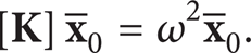
As already indicated, in the engineering practice of simulation of automotive body part stamping, the time of analysis often plays a critical role. Most of all, however, the FEM models of body parts should be adequate to the real parts; that is, the obtained geometric models of stamped parts should be consistent with reality. To assess the compatibility of the simulation results with reality, the shape of the stamped part from Figure 2 was measured using LineScan laser line scanner from Carl Zeiss. The view of the actual stamped part and the scan result in the form of the so-called cloud of points are shown in Figure 5.
View of the stamped part (a), scan result (b).
Then, the measuring points obtained during scanning were compared with the shapes of virtual stamped parts in DynaForm and AutoForm programs as a result of stamping simulation, where the spring-back effect was taken into account.
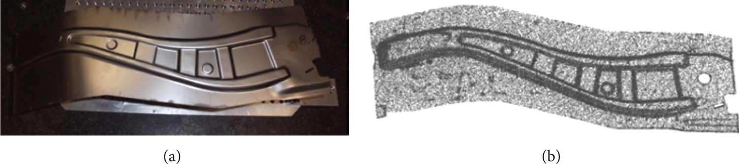
As the nodes of the stamped part FEM model are not consistent with the measuring points obtained during scanning, the comparison was made by means of Geomagic Qualify program, which enables finding the matching pairs of points, one of which is the point of the cloud received from the scanner and the second is the node of FEM model after simulation, located in the closest position. For the quantitative assessment of the compatibility of the simulation results with the measurement results, histograms showing the distribution of the shortest distances of the FEM model nodes from the real surface of the stamped part mapped with the scanner deviations e were determined. The cloud of points from the scanner consisted of 78,644 points. Figure 6 presents the comparisons between the results of the simulation in DynaForm and measurement (a) in AutoForm and measurement (b) and the resulting histograms showing comparisons between deviations e of the simulation results in DynaForm and AutoForm programs with the measurement results from the scanner (c). The bars in the graph represent the percentage share of deviations within the specified ranges and the lines in the graph illustrate trends determined by using a two-point moving average.
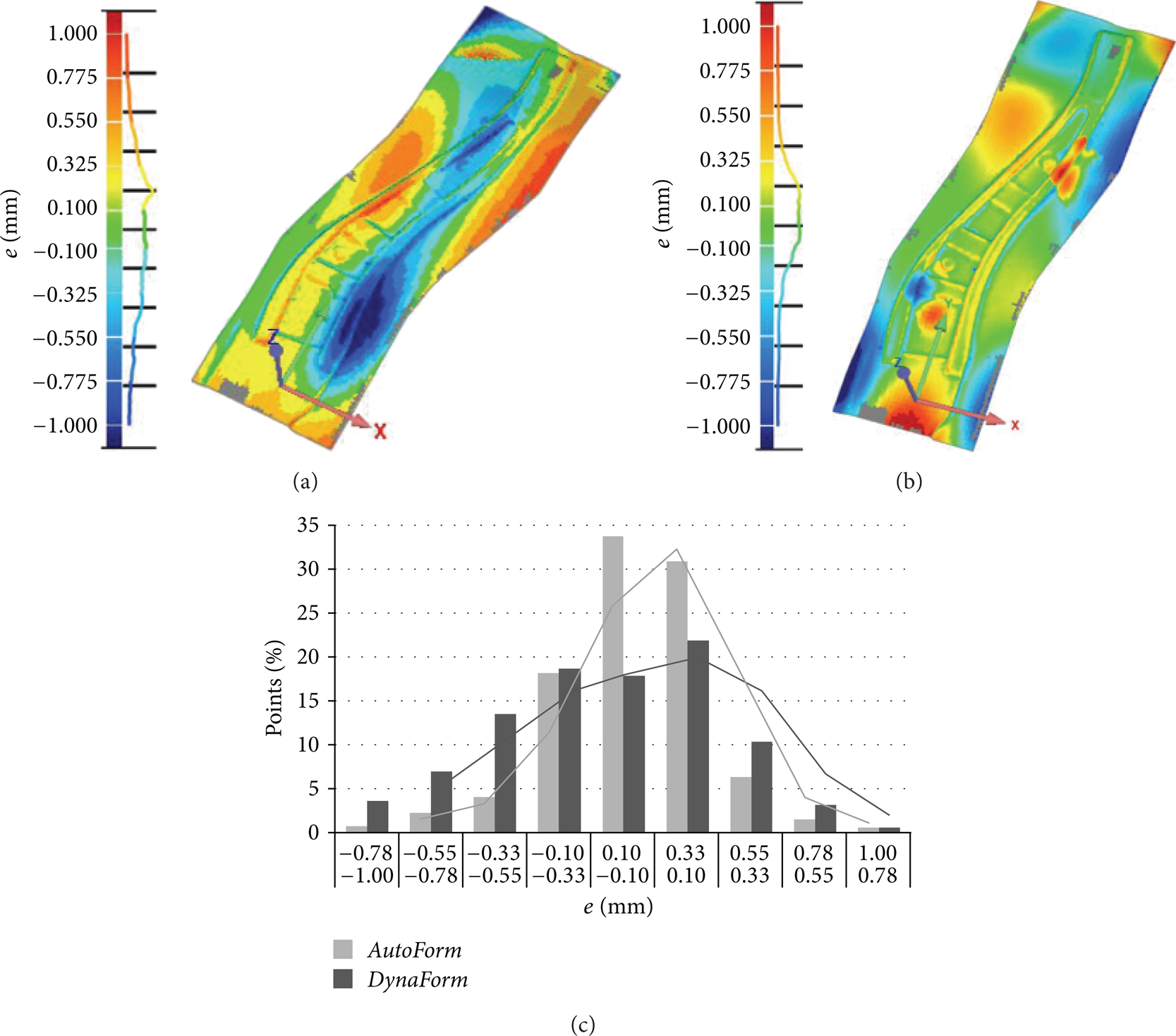
Comparison of the results of the simulation in DynaForm (a), in AutoForm (b), and in the measurement and of the histograms showing the distribution of deviations in the measurement and simulation results (c).
The compliance of the stamping simulation results in both programs with the measurement results can be assessed as very good, as more than 97% deviations are within the tolerance range of ±1 mm, and the average percentage deviation is very close, because for DynaForm it amounts to 10.78% and for AutoForm −10,99%. The average positive and negative values of deviations e, determined for all measurement points, equalled +0.267/−0.385 mm for DynaForm and +0.201/−0.210 mm for AutoForm. By analysing the trend line in the graph shown in Figure 6, it can be observed that DynaForm gives a more even distribution of deviations, whereas AutoForm provides a greater percentage share of points with the smallest deviations from the actual stamped part. The compliance of the simulation and measurement results was also compared in two selected characteristic sections, A-A (longitudinal) and B-B (cross), shown in Figure 2. In the longitudinal section A-A, the values of deviations e for all measuring points were in the ranges of −1.37/+0.975 mm with a standard deviation of 0.461 mm for DynaForm and −0.306/+1.103 mm with a standard deviation of 0.223 mm for AutoForm, while, in the cross section B-B, they were −0.841/+0.795 mm with a standard deviation of 0.434 mm and −0.509/+0.338 mm with a standard deviation of 0.192 mm, respectively.
7. Conclusions
The numerical effectiveness of simulation of metal sheet stamping for automotive body parts is mostly affected by
the complexity of the FEM model, the measure of which is the number of finite elements/nodes and the resulting number of degrees of freedom of the model; the user can reduce it by means of tools available in stamping simulation software, which do not significantly compromise the quality of the analysis results,
methods of solving the stamping simulation task and potential simplifications of the FEM model used by solvers of specific programs; the user has very limited ability to influence the solving methods, in real terms, knowing the differences between the methods used by specific solvers and possible simplifications of the FEM model; they may choose the one that ensures shorter computation time without compromising the quality of solutions.
Based on the comparison of the simulation results for a typical stamped part, an automotive body part, including the analysis of the spring-back effect in DynaForm and AutoForm programs and the comparison of the computation and measurement results, it has been found that the compliance of the simulation results with reality is sufficient for the engineering practice. The results obtained from AutoForm program are characterized by a smaller range of deviations of simulation results from the reality and a greater percentage share of the areas of the model with the smallest deviation from the actual stamped part. The comparison of the numerical effectiveness of the solvers shows that AutoForm definitely ensures a shorter time of analysis.
Conflict of Interests
The authors declare that there is no conflict of interests regarding the publication of this paper.