
Abstract
Electrochemical machining is widely used in the processing of difficult-to-machine metal materials. And through-mask electrochemical machining is a very important technology in the processing array structure of difficult-to-cut metal materials. Traditional through-mask electrochemical machining always uses a photoresist as the mask. The production process of a mask is complicated, and the mask cannot be reused. In this paper, through-active-mask electrochemical machining to process array structure in difficult-to-machine metal materials was investigated. Compared with traditional electrochemical machining masks, a copper-clad laminate is used to make the mask by mechanical machining in through-active-mask electrochemical machining. Also, the mask does not stick together with the workpiece but covers the workpiece by mechanical compaction, so the mask can be reused. In order to ensure the mask is in close contact with the workpiece, we need to arrange many compaction circular cylinders within the flow channel. The influences on electrolyte flow of compaction circular cylinders were investigated. The distribution of the compaction circular cylinders affects the electrolyte flow state, thereby affecting the processing. By analyzing the electrolyte flow state for the different distributions of compaction circular cylinders, one can find the best distribution of compaction circular cylinders for the required processing.
1. Introduction
Parts with groups of holes or dimple matrix are widely used in the industrial fields of aviation, electronics, automotive, and others, such as cooling air tubes and air conduct damper bushing in aero engines, raster in electron microscopes, and surface textures on piston surfaces [1–3]. Parts with groups of holes always have stringent requirements about consistent aperture and accurate distribution of holes. The processed material should not show deformation or residual stress. Most difficult-to-cut metal materials such as titanium alloys or nickel-based superalloys are difficult to achieve these requirements. In order to meet these requirements, many authors have proposed various methods. Mousavi et al. used a self-vibratory drilling head to drill small-diameter deep holes, enabling productivity to be improved by eliminating retreat cycles [4]. Döring et al. researched the hole formation process in ultrashort pulse laser percussion drilling [5]. Lalchhuanvela et al. investigated the profile accuracy of drilling holes in alumina ceramics by ultrasonic machining [6]. Electrodischarge drilling of an Al2O3-TiC composite has been studied by Calignano et al. [7]. Compared with other methods, electrochemical machining (ECM) is an important machining technique. This technique has many advantages such as high machining efficiency, unlimited material hardness and toughness, no existing heat-affected layer and residual stresses in the parts, no tool wearing, and low production cost [8, 9]. Thanigaivelan et al. researched the mechanism of drilling microholes in copper by ECM and analyzed various processing parameters by Taguchi's quality design concepts [10]. Zhu et al. proposed an electrochemical drilling method of multiple holes in which reverse electrolyte flow is achieved in the way of electrolyte-extraction, instead of traditional forward electrolyte flow which often causes poor electrolyte flow conditions and so an unstable machining process [11]. Natsu et al. used electrolyte jet machining to process microdimple arrays of 300 μm in diameter [12].
Through-mask electrochemical machining (TMECM) is a very important technology in the processing holes matrix of difficult-to-cut metal materials [13]. Wu et al. fabricated a stainless steel protector for a weak fiber sensor by TMECM [14]. Qu et al. proposed using a dry-film photoresist as a mask to fabricate microdimple arrays by TMECM and successfully produced microdimple arrays with 94 μm in diameter and 22.7 μm deep on cylindrical inner surfaces [15]. The photoresist is coated on the workpiece in traditional TMECM, and then the mask is produced with a corresponding pattern on the photoresist by photolithography. Finally, the pattern is transferred to the workpiece by ECM. But the photoresist generally cannot be reused after ECM, so every process must involve coating the photoresist and photolithography. The mask for through-active-mask electrochemical machining is made from copper-clad laminate (CCL) using a printed circuit board drilling and milling machine. The mask covers the workpiece by mechanical compaction, so the mask can be reused.
However, in order to prevent the electrolyte infiltrating to the nonprocessing zone, the mask must be pressed on the workpiece by a special fixture. A flow channel was constructed between the fixture and the mask, arranged with a lot of compaction circular cylinders within the flow channel. These compaction circular cylinders will interfere with the electrolyte flow. Therefore, the distribution manner of the compaction circular cylinders must be rigorously analyzed.
This paper focuses on the influence on through-active-mask electrochemical machining of the compaction circular cylinders distribution manner. According to the theoretical flow around circular cylinders, the impact of compaction circular cylinders on processing was analyzed. And then we determined the best distribution manner of compaction circular cylinders for the processing.
2. Description of the Flow Field
A schematic diagram of through-active-mask electrochemical machining is shown in Figure 1. The mask with a group of microholes located on the workpiece is movable and can be reused after being processed. The fixture pressed the mask on the workpiece and is the cathode for ECM. A neutral electrolyte, such as NaNO3 solution, is pumped out with high speed between the fixture and the mask. The area of the workpiece exposed to the electrolyte can be dissolved when sufficient voltage is applied. In order to improve the machining accuracy, we improved two aspects of TMECM.
Double Sided Electrochemical Machining. For the purpose of reducing the machining taper of groups of microholes, we processed the workpiece from both sides as in Figure 1.
Dual Cathode and Reusable Mask. A special CCL is used as the mask, which has a copper layer only on one side. The copper layer is in contact with the clamp, which constitutes the dual cathode in order to improve the electric field distribution. Simultaneously, the special CCL can be machined into the mask by a printed circuit board drilling and milling machine and the mask can be reused.
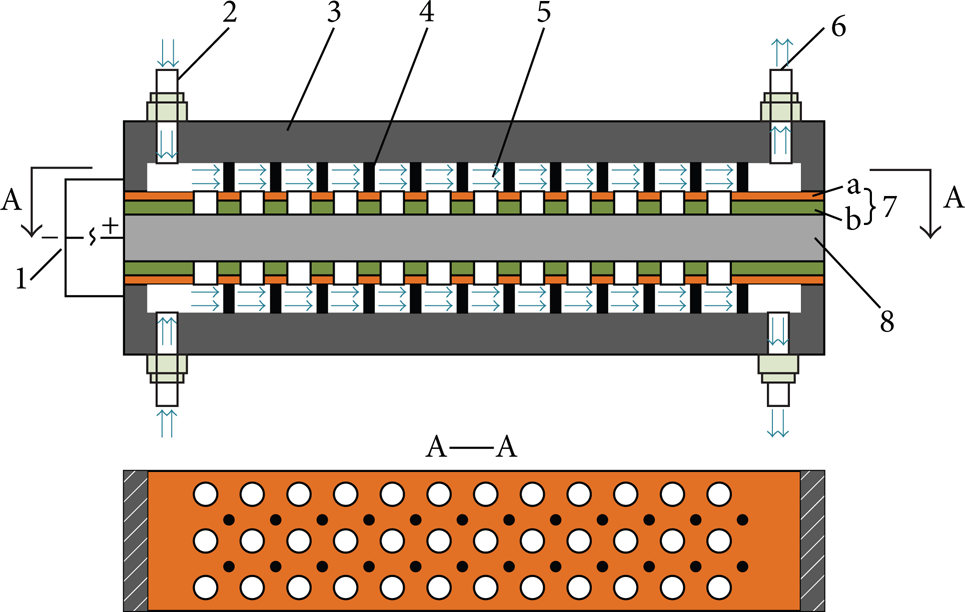
Schematic diagram of through-active-mask electrochemical machining. 1, power; 2, inlet; 3, fixture (cathode); 4, compaction point; 5, electrolyte; 6, outlet; 7, mask (a, copper layer (cathode); b, insulating layer); 8, workpiece (anode).
The flow field of through-active-mask electrochemical machining is the channel between fixture and mask, while the fixture extends many small compaction circular cylinders within the channel. The compaction circular cylinders are rubber cylinders, one end of each of which is fixed to the fixture and the other end presses on the mask. Therefore, the compaction circular cylinders interfere with the electrolyte flow similar to the problem of flow around a circular cylinder. According to the theoretical flow around a circular cylinder, under certain conditions (Re > 45) pairs of symmetric counter-rotating vortices appear as shown in Figure 2, which will cause pulse pressure in both cross-flow direction and streamwise direction [16–18]. Therefore, the processing zone must be arranged in an area not affected by the compaction circular cylinders (circular cylinders).

Schematic diagram of Kármán vortex street.
3. Simulation of Flow Field
3.1. Computation Model of Fluid
In the TMECM method of this paper, the cathode is stationary. The electrolyte is considered an incompressible fluid. Therefore, the Navier-Stokes equation of computation fluid dynamics can be used for this investigation. The mass and momentum conservation equations for the flow field of through-active-mask electrochemical machining are [19]

where ρ is the electrolyte density, v is the kinematic viscosity coefficient of electrolyte, u i is the electrolyte velocity vector, p is the electrolyte pressure, x i is the ith spatial coordinate, and f i is the mass force strength of fluid (in this paper, gravity is the only mass force acting on the electrolyte, so f i = g i ).
In the through-active-mask electrochemical machining process, electrolyte flows between the fixture and the mask. The thickness of the channel between the fixture and the mask is 1 mm, and the width is 100 mm. In this experiment, the electrolyte velocity is about 15 m/s. In this case, the Reynolds number is greater than 20 000. Therefore, a renormalization group (RNG) κ-∊ turbulence model is used, which is suitable for high Reynolds number flow problems. Turbulent dissipation rate ∊ is introduced to (1), and through a RNG method one obtains the RNG κ-∊ model [19]. The turbulent kinetic energy equation and dissipation rate equation of this model are

among which

where κ and ∊ are the turbulence kinetic energy and dissipation rate, G x is the turbulent kinetic energy caused by mean velocity gradient, μeff is the effective viscosity, G b is the turbulent kinetic energy caused by buoyant force (in this case, we do not consider the impact of buoyancy, so G b = 0). μ and μ t are dynamic viscosity and turbulent viscosity; ακ and α∊ are Prandtl number of the turbulence kinetic energy and dissipation rate (ακ = 1.0, α∊ = 1.3). C1∊, C2∊, C3∊, and Cμ are empirical constants in equations (C1∊ = 1.44, C2∊ = 1.92, C3∊ = 0.09, and Cμ = 0.09).
3.2. Geometry Model and Boundary Conditions
According to the theoretical flow around a circular cylinder [20], four cases will be simulated, which are single circular cylinder, double cylinders in a tandem arrangement, double cylinders in a side-by-side arrangement, and a multicylinder array, as shown in Figure 3. First, we simulate a single cylinder affecting the electrolyte flow and analyze changes in flow rate and vorticity distribution of cylinder wake flow. Second, we simulate the double cylinders tandem arrangement within the electrolyte flow field. Analysis is done of the influence on electrolyte flow of the different ratio of the two-cylinder gap (L) and the diameter of the cylinders. Third, simulations are carried out for cylinders in side-by-side arrangements similar to the second step. Fourth, the electrolyte flow state with a multicylinder array has been simulated. The configuration of the multicylinder array is based on the first three steps of the analysis. In these simulations, the flow field is a cuboid of length 300 mm, width 100 mm, and thickness 1 mm. In order to reduce the impact of the flow field, the diameter of the cylinder should be as small as possible. But compaction circular cylinders must meet certain strength. Therefore, the diameter is determined to be 1.5 mm.

Schematic diagram of four cases: (a) single circular cylinder, (b) tandem arrangement, (c) side-by-side arrangement, and (d) multicylinder array.
In the ECM process, a high electrolyte flow rate is helpful in improving the quality and efficiency of drilling holes [21]. It is generally believed that the flow velocity should be sufficient to achieve fluid turbulence and to ensure a substantially constant temperature of the processing zone. According to these two requirements, the speed value can be obtained from the following equations:

where 2300 is the critical Reynolds number of laminar and turbulent flow, ν is the coefficient of kinematic viscosity, D h is the hydraulic diameter, i is the current density, κ o is the conductivity of the electrolyte, C1 is the heat capacity of the electrolyte, ΔT is the allowed temperature rise, and L is the flow length. According to the experimental conditions and (4), the minimum speed is introduced as umin = 13.2 m/s.
In this simulation, inlet velocity and outlet pressure are used as the boundary conditions. We chose the inlet velocity as 15 m/s to simulate the flow field state. The outlet is directly connected to the atmosphere, so the outlet relative pressure is 0.
3.3. Simulation Results and Analysis
According to the above boundary conditions, the simulation results for each case of different flow rates are obtained by fluid analysis software. Figure 4 shows the contours graph of electrolyte velocity with a single circular cylinder. The electrolyte flow rate is close to zero in zone “I” as shown in Figure 4. The electrolyte flow rate is higher than 15 m/s in zones “II” and “III” of Figure 4, but the flow state is unstable. The electrolyte flow state is stable in zones “IV” and “V” as shown in Figure 4. Therefore, the processing zone can be selected in zones “IV” and “V.”

Contours graph of electrolyte velocity with a single circular cylinder.
A different electrolyte flow state was simulated for different ratios of L/D as shown in Figure 5. The electrolyte velocity is close to zero between the two circular cylinders when L/D < 3. So the double cylinder can be seen as an ellipsoid when L/D < 3. The velocity is unstable in zones “I” and “II” as shown in Figures 5(a) and 5(b). When L/D ≥ 3, the velocity is close to 3 m/s between the two circular cylinders, but this value is far less than the 13.2 m/s which is the minimum required in processing. However, the velocity is acceptable for processing in zones “I” and “II” as shown in Figures 5(c) and 5(d), the value of which is not only greater than 13.2 m/s but also relatively stable.

Contours graphs of electrolyte velocity with two circular cylinders in tandem arrangement: (a) L/D = 1.5, (b) L/D = 2, (c) L/D = 3, and (d) L/D = 4.
The simulations of electrolyte velocity with two cylinders in a side-by-side arrangement are shown in Figure 6. Figures 6(a) and 6(b) show that the velocity is less than 13.2 m/s in a wide area after the circular cylinders when L/D < 3. However, when L ≥ 3D the velocity of zone “I” (as shown in Figures 6(c) and 6(d)) is greater than 15 m/s and stable. To further analyze the regional distribution of velocity, a line l is selected in the middle of two cylinders (as shown in Figure 3(c)), and velocity curves of l at each case are obtained from inlet to outlet, as shown in Figure 7. From the velocity curves, we can find two conclusions which are as follows.
The electrolyte flow rate increased rapidly when the electrolyte flowed through the two cylinders, and then the electrolyte flow rate sharp decline and the velocity are less than 13.2 m/s until the outlet when L/D < 3. Therefore, it is not suitable for processing when L/D < 3.
When L/D ≥ 3 the change of the electrolyte flow rate is relatively stable and the velocity value is more than 13.2 m/s. Therefore, it is suitable for processing when L/D ≥ 3.
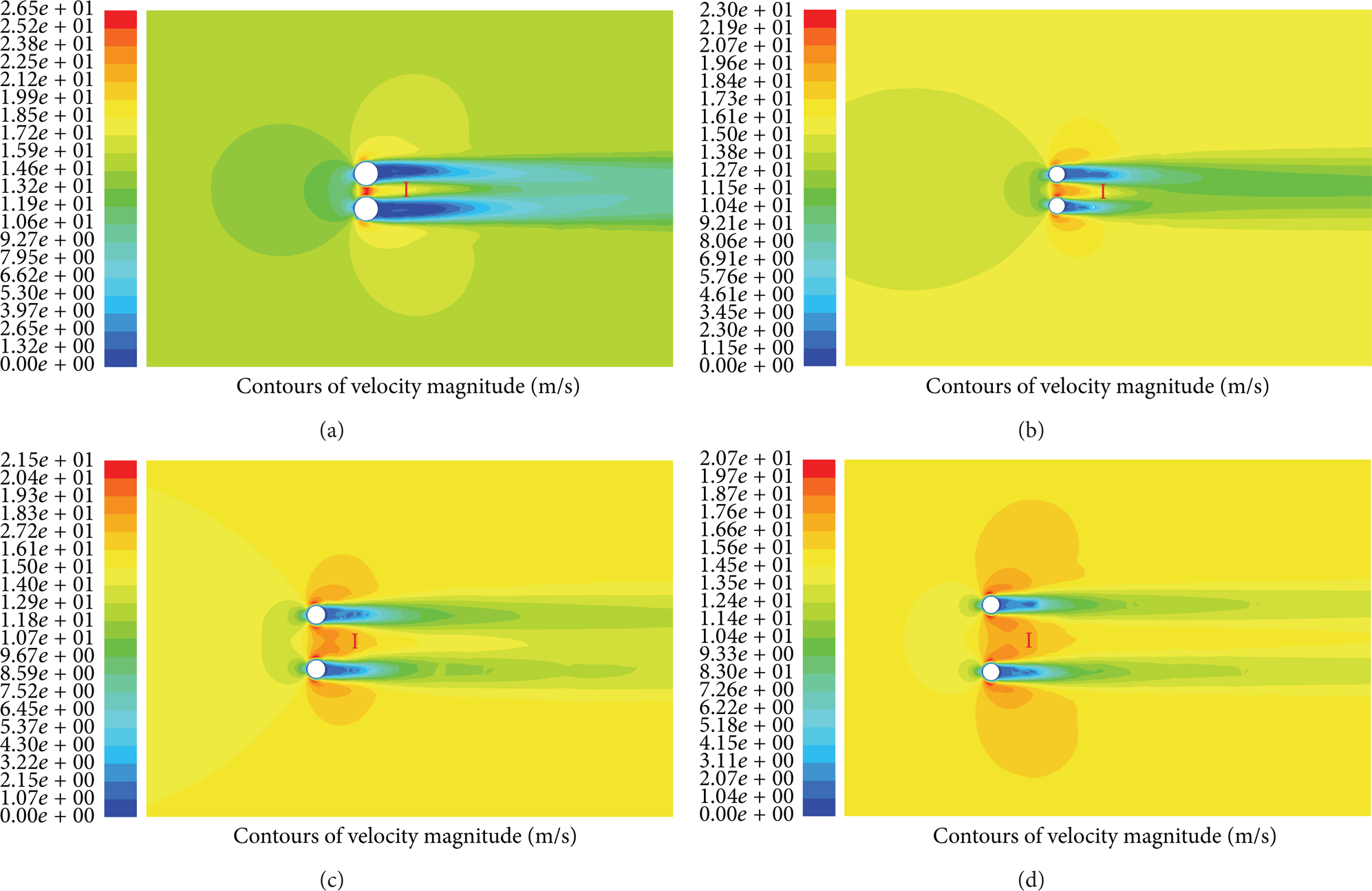
Contours graphs of electrolyte velocity with two cylinders in a side-by-side arrangement: (a) L/D = 1.5, (b) L/D = 2, (c) L/D = 3, and (d) L/D = 4.

Velocity curves of l at each case.
Column spacing of the multicylinder array is defined as L and line spacing is defined as H as shown in Figure 3(d). Based on the above simulation of the flow around two circular cylinders, we can find that the column spacing of the multicylinder array should meet the requirement L ≥ 3D and line spacing should meet the requirement H ≥ 3D, because this can ensure the flow field is independent and stable between the adjacent two rows of circular cylinders. The final decision for column spacing of the multicylinder array is L = 3D and the line spacing is H = 3D. So the column spacing and line spacing are both 4.5 mm. In the first place, we simulated a simple circular cylinder matrix (2 × 2) arrangement. Then the flow field with multicylinder matrix (13 × 26) arrangement was simulated. The simulation results are shown in Figure 8. Zone “I” as shown in Figure 8(a) can be accepted as the processing zone, because the electrolyte flow velocity is greater than 15 m/s and the flow state is stable. In order to quantify the changes of electrolyte flow rate in the middle of circular cylinder matrix (2 × 2), we selected one velocity value every 4 mm starting from the inlet to outlet. The velocity value curve as shown in Figure 8(b). The velocity value curve shows that electrolyte flow rate is the highest and stable in the 10 mm long area of the circular cylinder matrix center. As shown in Figure 8(c), the entire flow field is divided into a number of flow paths, and the electrolyte flow velocity of each flow path is consistent and stable, while the electrolyte flow velocity reaches 18 m/s. Therefore, these flow paths can be used as the ECM zones.

(a) Contours graph of electrolyte velocity with 2 × 2 circular cylinder matrix. (b) Velocity curves of the circular cylinder matrix center. (c) Contours graph of electrolyte velocity with the multicylinder array.
4. Experimental
In order to verify the simulation results, we designed a through-active-mask electrochemical machining test of machining a group of holes. The distribution of compaction circular cylinders is a matrix of 13 × 26 that is mentioned in the above discussion. The mask holes are uniformly distributed in the matrix as shown in Figure 9. The experimental conditions are listed in Table 1.
Experimental conditions.

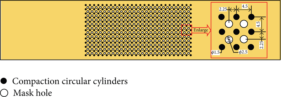
Schematic diagram of mask hole distribution.
The photo as shown in Figure 10 depicts experimental results and an enlarged view of a single hole. In order to check the consistency of the group of holes, we randomly measured the diameter of 200 holes by three-dimensional profilometer (DVM5000, Leica, Germany). Table 2 lists the diameter of all the holes. The minimum diameter is 3.192 mm and maximum diameter is 3.236 mm. So the deviation of the aperture is less than 50 μm. The results show that the consistency of holes is good. Thus, the distribution of compaction circular cylinders can guarantee the consistency of processing a group of holes.
Diameter value list.

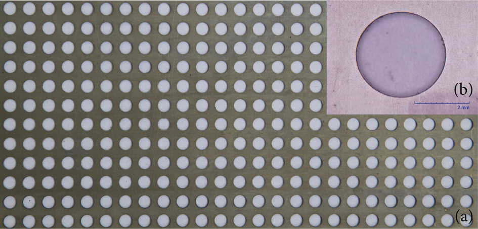
Experimental results. (a) Photo of experimental results. (b) Enlarged view of a single hole.
5. Conclusions
In this paper, we analyzed the influence on flow field of compaction circular cylinders in the through-active-mask electrochemical machining process. Based on simulations of the flow field and experimental investigation, the following conclusions can be drawn.
The compaction circular cylinders significantly affect the flow velocity and flow state of the electrolyte. When the electrolyte flows around a circular cylinder, there will be multiple regions with different flow velocities. One must select the appropriate region as the ECM zone.
A suitable arrangement of the compaction circular cylinders can divide the entire flow field into a number of flow paths, and the electrolyte flow state of each flow path is stable and consistent. This electrolyte flow field can be used to process groups of holes by through-active-mask electrochemical machining.
The experimental results show that the distribution of compaction circular cylinders based on the simulation result can allow the processing of a 12 × 25 matrix of holes at one time, with a deviation of aperture of less than 50 μm.
Conflict of Interests
The authors declare that there is no conflict of interests regarding the publication of this paper.
Footnotes
Acknowledgments
The work was financially supported by the National Natural Science funds (51275233) and the Aeronautical Science Foundation of China (2012ZE52068).