
Abstract
Since CO2 Stimulation in Horizontal Wells can avoid the problem of steam flooding, clay swelling, and sand production, it has been carried out in many fields. To improve the research on the controlling factors and their influence and establish a specific reservoir selecting method, this paper founded the components and geology model according to typical heavy oil reservoirs firstly. Comparing with pilot test, the theoretical model result could give expression to the characteristic of large water ratio descend rang, long period of validity, and high rounds effectiveness. Secondly, this study designed simulation scheme including factors of geology, development, and stimulation technology, to filter the controlling factors of the oil incremental and well reopened water cut and describe their influence. Based on it, we proposed a quick filter criterion to choose heavy oil reservoirs for CO2 stimulation.
1. Introduction
The technology of horizontal wells has applied in many viscous oil reservoirs, with process of steam stimulation and steam drives commonly. However, injected water and/or steam leads to not only clay swelling and sand production but also fast oil production decrease in high rounds stimulation, especially in water-sensitive reservoirs. The horizontal well CO2 stimulation has been used in enhanced oil recovery [1–4], high water cut reservoirs, heterogeneous reservoirs, and viscous oil not fit for thermal recovery since 1970s. Its mechanism include reducing oil viscosity, expanding oil volume, promoting solution-gas-drive, decreasing interfacial tension, acidizing, improving mobility ratio and density ratio, and increasing sweep efficiency. The result of this technology in Pisticci fields is worse than in Paradis, Trinidad and Tobago field [5–7], because of high gas-oil ratio [8].
Since 1970s, there is tremendous research on optimizing cyclic CO2 injection volume, injection rate, soaking time, production velocity of vertical well CO2 stimulation by laboratory experiment, and simulation research [9, 10], but little information is available on geology factors including formation dip, Heterogeneous degree, development factors including initial water cut, wellbore condition, and location of horizontal branch.
To solve this problem, using theoretical model method, this paper improves the study on controlling factors in horizontal well CO2 stimulation of heavy oil, rating the sensitive degree of geology, development, and technological parameters, and establishing viscous oil reservoir selecting method for CO2 stimulation.
2. Dynamic Modeling
2.1. Component Modeling
To facilitate the numerical simulation, the typical heavy oil components were incorporated into nine pseudo components according to the principle of property similarity. Based on matching the fluid properties and the result of expansion experiment, we obtained the ratio of nine components which reflects the real formation fluid phase state (Table 1). In addition, the corresponding underground oil viscosity is 87 cp, oil density is 0.992 g/cm3, bubbling pressure is 5.9 MPa and initial gas oil ratio is 21 m3/m3. The PVT data is calculated by PR equation of state.
Components of pseudocomponent.

2.2. Geology Modeling
We established a geological model of horizontal well CO2 stimulation, whose plane size is 700 m by 200 m; the grid plane size is 10 m by 10 m. Typically, horizontal well area grid size is 5 m by 5 m (Figure 1); the model thickness was divided into 11 layers, where the 150 m horizontal branch was located in layer 3. The average porosity is 0.26; the average permeability is 30 × 10−3 μm2.

Geology model.
2.3. Simulation of Character in Pilot Test
The horizontal well CO2 stimulation pilot test was carried out in JD oil field (Table 2). The numerical methods used in the simulations are adaptive implicit method.
Pilot test area properties.

CO2 stimulation was carried out in a total of 45 horizontal wells, of which geology, development factors are different, such as interlayer, thickness, initial water cut, and horizontal branch position. Different injection process parameters, such as cyclic CO2 injection amount, injection rate, soaking time, and production velocity, were designed for different horizontal well, and the maximum cycle oil increment is up to 2000 t. The CO2 stimulation dynamic characteristics can be summarized as follows.
(1) The water cut is low when the CO2 stimulation well is reopened. Before the horizontal well CO2 huff and puff, the average of water cut is 94%, as the water cut is 43%, on average, after CO2 stimulation. Some of the wells’ water cut specially could become 2% from 99%, showing that the CO2 can remove the water near the wellbore, and density difference between oil and CO2 makes oil full of this part.
As Figure 2 shows, the initial water cut of well W1 is 15%. When the water cut reached 97% on July 9, 2011, 325 t CO2 were injected during 4 days. After stuffy well of 20 days, water cut became 1% and gradually rose to 38% a month later. After five months, water cut was up to 97% again, and CO2 stimulation validity period is over.

Low well reopened water cut by CO2 stimulation.
(2) CO2 stimulation validity period last for more than 3 months. The statistics of 45 oilfield CO2 stimulation pilot test results show that average of validity period lasts for 250 days. The reason might be that water flow resistance and swept volume is enlarged because of the making of foam in low pressure area near wellbore.
As Figure 3 shows, the initial water cut of well W2 is 28%. When the water cut reached 92% on October 18, 2011 because of high production rate, 300 t CO2 were injected during 3 days. After stuffy well of 20 days, water cut became 18%. After seven months, water cut was up to 92% again, and CO2 stimulation validity period lasts for 227 days.
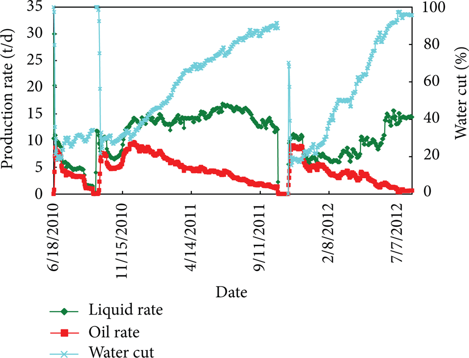
Validity period last for more than 3 months.
(3) Multicycle CO2 stimulation is still effective. Nine members of the 45 horizontal wells have carried out two rounds of CO2 stimulation. In spite of the fact that increased oil production is reducing with the increase of throughput rounds, the maximum oil production of second round is up to 1000 t.
As Figure 4 shows, the initial water cut of well W3, located in the peak of formation, is 4%. Because of high water cut, the first round CO2 stimulation was implemented in October, 2008. The water cut became 17% and CO2 stimulation validity period lasts for 250 days, which increased oil production 691 t. The second round CO2 stimulation was implemented in June, 2007. The water cut became 14% and CO2 stimulation validity period lasts for 228 days, which increased oil production 1000 t.

Effective in high round.
Typical theoretical model's 3 times CO2 stimulation parameters are designed as injecting CO2 with rate of 100 t/d for 3 days when water cut rises to 99%, then shut well for 30 days. When the well is reopened, the water cut is 20%, 19%, and 20%, respectively; the period of validity is in more than one year; the increased amount of oil in 2nd and 3rd round stimulation is, respectively, 442 m3 and 277 m3, inosculates with the dynamic characteristics of pilot test (Figure 5). Analysis of CO2 distribution and water saturation (Figures 6, 7, and 8), it shows that the typical model can simulate the phenomenon of CO2 driving water near wellbore and improving microscopic oil displacement effect. In conclusion, typical theoretical model can reflect the actual effect of heavy oil reservoir horizontal well CO2 stimulation.

Result of typical theoretical model.

Water saturation before the 2nd CO2 injection.

Water saturation after the 2nd CO2 injection.

CO2 distribution after the 2nd CO2 injection.
2.4. Simulation Project Design
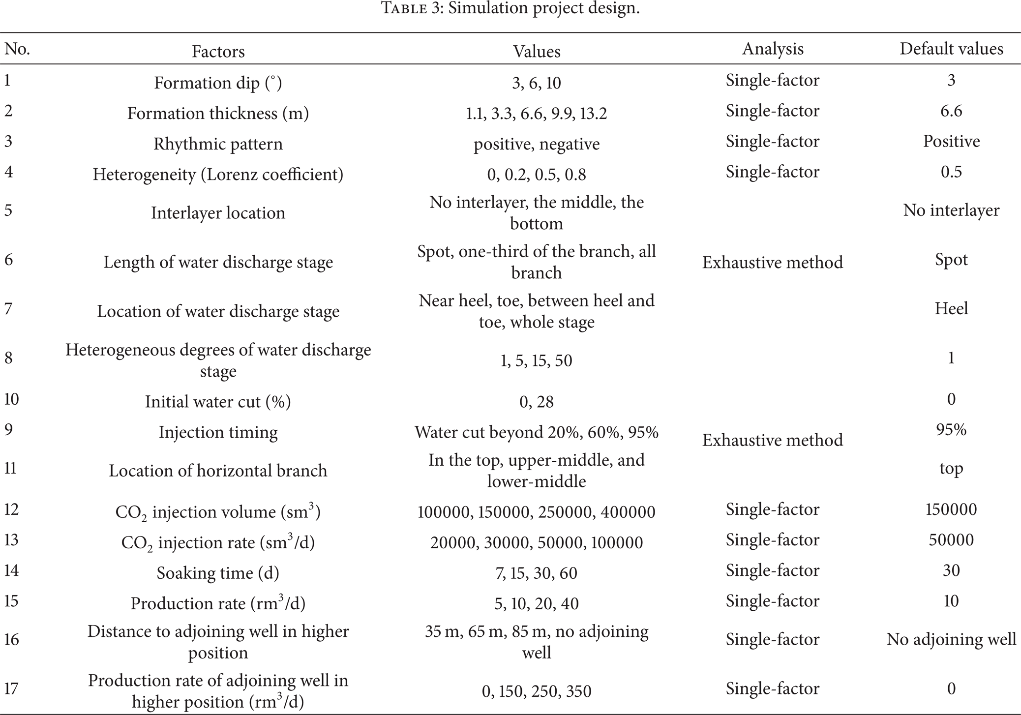
The result of horizontal well CO2 stimulation in heavy oil reservoirs is affected by the geology factors, such as formation dip, net thickness, rhythmic pattern, heterogeneity, and interlayer location; the development factors, such as wellbore condition, initial water cut, horizontal branch location, and production of adjoining well in high region; and the technology factors, such as stimulation time (water cut), injection CO2 volume, injection rate, soaking time, and production rate. Enlarge the typical value distribution of viscous oil reservoirs properly, and simulation project is designed with 335 instances (Table 3). Lorentz coefficient especially is used to quantitate vertical heterogeneity (Figure 9).
Simulation project design.

Map of Lorenz curve.
3. Controlling Factors Selecting
The controlling factors of CO2 stimulation in heavy oil is selected by analyzing the change law of well reopened water cut and oil increment, which is defined as production oil volume during validity periods.
3.1. Controlling Factors for Oil Increment
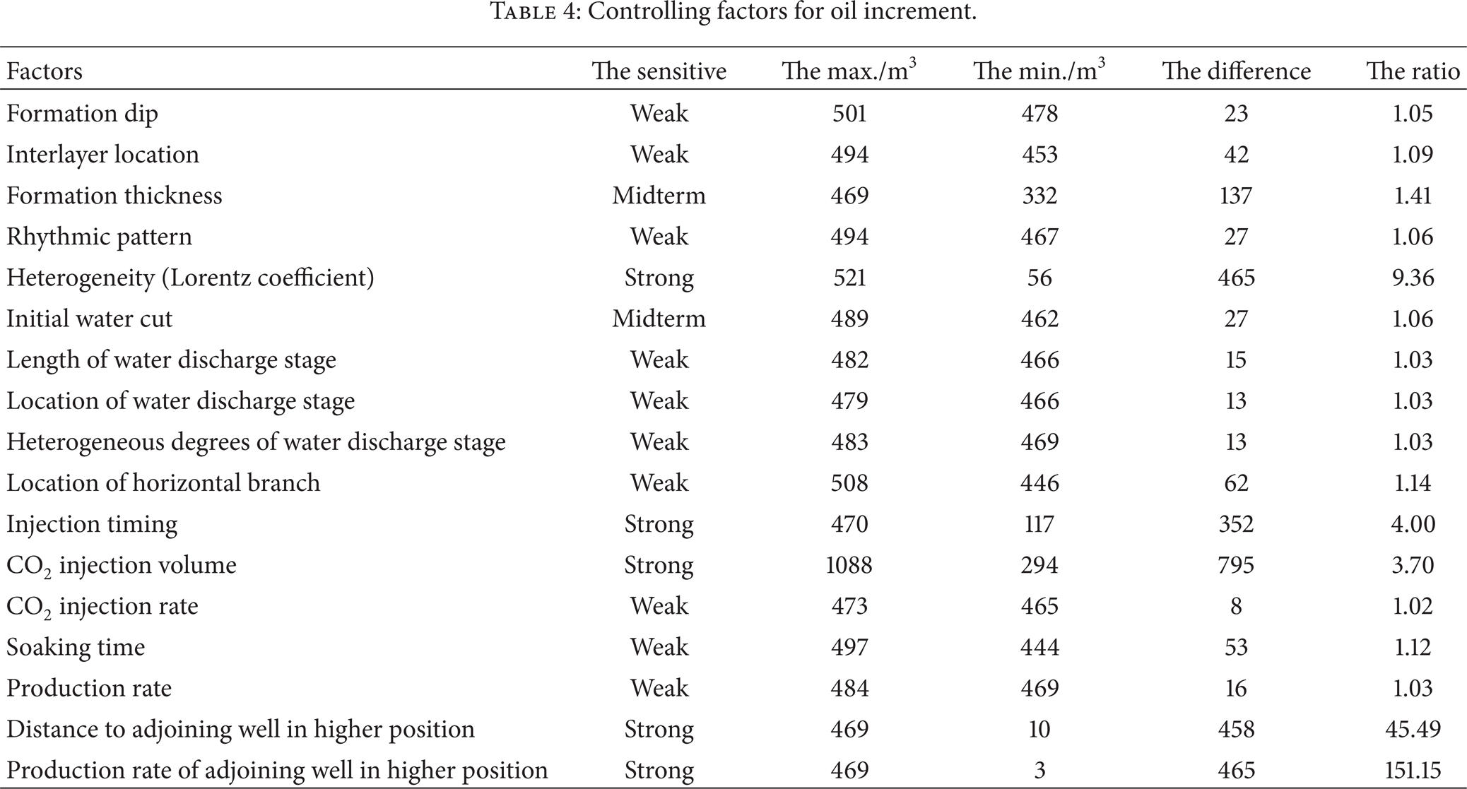
Since oil increment is positive correlation with the result of CO2 stimulation, defining the standard as the difference and ratio of the maximum and minimum oil increment, controlling factors were selected (Tables 4 and 5). Specific standard is as follows:
not sensitive: no influence to oil increment;
weak sensitive: has influence to oil increment and the difference below 100 m3 or the ratio below 1.4;
midterm sensitive: has influence to oil increment and the difference beyond 100 m3 and the ratio beyond 1.4;
strong sensitive: has influence to oil increment and the difference beyond 200 m3 and the ratio beyond 2.
Controlling factors for oil increment.
Oil increment change law.

Above all, the controlling factors for oil increment are formation rhythmic pattern, stimulation time, injection CO2 volume, and adjoining well in high region. It shows the following.
Horizontal well CO2 stimulation of viscous oil has great potential in popularizing in oil fields as its controlling factor is in low number.
The foundation and precondition to CO2 stimulation successful is reasonable parameter of CO2 injection 10 and oil production.
3.2. Controlling Factors for Well Reopened Water Cut
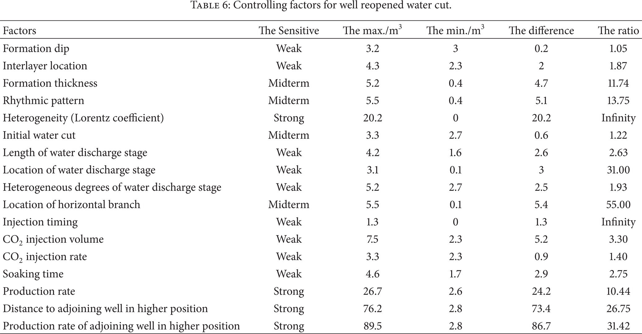
Since well reopened water cut has effect on the result of CO2 stimulation, defining the standard as the difference and ratio of the maximum and minimum well reopened water cut, controlling factors were selected (Tables 6 and 7). Specific standard is as follows:
not sensitive: no influence to oil increment;
weak sensitive: has influence to the water cut and the difference below 10% and the ratio below 10;
midterm sensitive: has influence to the water cut and the difference below 10% and the ratio beyond 10;
strong sensitive: has influence to the water cut and the difference beyond 20%.
Controlling factors for well reopened water cut.
Well reopened water cut change law.

Above all, the controlling factors for well reopened water cut are formation rhythmic pattern, production rate, and adjoining well in high region, similar to oil increment. It shows that the result of CO2 stimulation is determined by reservoirs characteristics, adjoining wells and parameter of CO2 injection.
4. Reservoir Selecting Method
By previous work on CO2 stimulation field test, reservoirs disagree with CO2 stimulation when we have the following situations.
Fractures are distributed near wellbore.
A high production rate adjoining horizontal well is located in higher position.
Horizontal branch is located in water layer, suggesting water plugging before CO2 injection.
Initial water cut is beyond 90%, suggesting water plugging before CO2 injection.
Based on the result of Chapter 3, we described a reservoir selecting method for CO2 stimulation in viscous oil preliminary (Table 8), and this method has been applied on pilot test.
Reservoir selecting method.

5. Conclusions
The typical theoretical model can reflect the actual effect of heavy oil reservoir horizontal well CO2 stimulation.
The controlling factors for oil increment and well reopened water cut are formation rhythmic pattern, stimulation time, injection CO2 volume, and adjoining well in high region.
The reservoir selecting method was established including 12 criteria.
Conflict of Interests
The authors declare that there is no conflict of interests regarding the publication of this paper.
Footnotes
Acknowledgment
This work was supported by Major National S&T Projects (2011ZX05009, 2011ZX05054, and 2011ZX05011).