
Abstract
This study primarily focuses on the use of radio frequency identification (RFID) as a form of traffic flow detection, which transmits collected information related to traffic flow directly to a control system through an RS232 interface. At the same time, the sensor analyzes and judges the information using an extension algorithm designed to achieve the objective of controlling the flow of traffic. In addition, the traffic flow situation is also transmitted to a remote monitoring control system through ZigBee wireless network communication technology. The traffic flow control system developed in this study can perform remote transmission and reduce traffic accidents. And it can also effectively control traffic flow while reducing traffic delay time and maintaining the smooth flow of traffic.
1. Introduction
With the rapid growth in the number of vehicles everywhere, road traffic conditions are becoming increasingly crowded, complicated, and chaotic. Countries all over the world are actively developing intelligent transportation systems (ITS), hoping to tap into the power of computer and communication networks to improve vehicle, road, and traffic conditions. Such an improvement in transportation system operations can lead to improvement in the safety and efficiency of today's transportation network. Because the international transport sector pays closer attention to and provides fuller cooperation in the promotion of ITS, the further development of the potential of a dynamic signal control model per second basis [1–5] for close integration into developing telecommunication and control technologies to produce more intelligent traffic control timing signals in real-time has become a key issue in long-term resource investment. The belief is that this trend will continue well into the future. The conventional traffic control methods include fix-time control, time-of-day control, vehicle actuated control, semiactuated control, green wave control, area static control, and area dynamic control [3]. However, there is no system meeting the adaptive characteristic. This is because the traffic control system is nonlinear, fuzzy, and nondeterministic, and thus traditional methods of modeling and control cannot work very well. Although some significant artificial intelligence (AI) methods such as fuzzy logic [4–7], neural network [8–10], evolutionary algorithms [11–13], and reinforcement learning [14–16] have been proposed to tune the cycle length and splits adaptively, the success in timing optimization and convergence rate are still limited. The cycle length and splits could be determined by using the fuzzy control method, and thus that could shorten the queue and reduce total traffic delay. However, most researchers work at controlling an isolated intersection with the fuzzy control method. Few apply this method to the coordinated control of area traffic because it is a complex large-scale system. There are many interaction factors, and it is difficult to describe the whole system using some qualitative knowledge. This is the limitation of fuzzy control methods. The applying effect of artificial neural network (ANN) depends on its generalization capability. So the samples should be ergodic and the learning process should converge to the global optimal point. In fact, it is hard to meet these conditions for a real application. Therefore, further development of ANN is needed for applying this method to traffic lights control. The evolutionary algorithms such as genetic algorithm, ant algorithm, and particle swarm optimization are all biomimetic methods for global optimization. Therefore, evolutionary algorithms are not likely to be trapped in local optima because of their characteristics of random search and implicit parallel computing. Also, when meeting a large-scale problem, these methods will spend much time to converge to the optima. It is disadvantageous for on-line optimization of area traffic coordinated control. In addition, the convergence rate is sensitive to parameters selected, which depend on practical problems to be solved. Thus, applying the evolutionary algorithm to area traffic coordinated control is limited. The advantage of reinforcement learning is that it is not necessary to set up the mathematic model for the external environment. However, there is also the disadvantage of converging slowly. It can be easily understood: compared with those methods requiring mathematical model for the external environment, it provided less information about the environment. So, it is impossible to converge quickly.
In traditional traffic detection, infrared detection systems are most commonly used for their ability to count traffic. However, when vehicles are traveling either too closely to each other or in parallel at high speed, such a traffic detection system can easily make a misjudgment, resulting in the failure of a supposedly intelligent traffic signal system to adjust the timing of traffic signals. Radio frequency identification (RFID) is an alternative system that is capable of handling data of a high density, is highly secure, reads quickly, and carries a policy which denies unauthorized replication or modification of data without permission [6–10]. In data transmission, the development of wireless communications technology and the rapid propagation of the Internet have led to the increasing importance of machine-to-machine (M2M) data transmission [11–15]. Therefore, this study combines RFID with ZigBee wireless network communication to provide a more intelligent control of remote traffic flow using the extension algorithm.
2. RFID and ZigBee Wireless Network Communication System
RFID data is recorded just like an IC card in a data carrier card, except that the data is exchanged through magnetic or electric fields, so that it is completed without any direct physical contact or human observation. RFID mainly uses tags as its basic components to send data back to the reader in a noncontact manner, which is finally then transmitted to the host side using RS232 for data application [6–10]. The intelligent traffic light control system (ITLCS) mentioned in this paper uses the passive RFID system that complies with the IEEE 802.11p protocol for detecting traffic flow. The wireless access in the vehicular environment (WAVE) interface is mainly used for vehicular wireless communication and is in accordance with the applications of the intelligent transportation system (ITS). In Taiwan, highway tolls are currently collected using an electronic toll collection system. More than 99% of vehicles are expected to have WAVE e-tags installed. For vehicles at high speed, the daily correct toll collection rate has reached 99.98%, indicating high detection accuracy. In the future, when 100% of vehicles have installed the WAVE interface, the ITLCS can be comprehensively applied to traffic light control for managing traffic flow on horizontal roads.
ZigBee is a wireless networking protocol developed by ZigBee Alliance that uses IEEE 802.15.4 standard specifications for its media access layer and physical layer [11–15]. It is a short distance wireless communication technology with a simple structure that is low in power and has a low transmission rate. It transmits to a distance of up to 10 m using 2.4 GHz and 900 MHz free available bands at a transmission rate of 20 to 250 Kbps. The network architecture is designed with master/slave attributes and is capable of two-way communication. According to technical specifications, ZigBee is a (i) power saving; (ii) highly reliable; and (iii) highly scalable technology.
3. Traffic Signal Control System Architecture
3.1. Programmable System on Chip
This study uses a Cypress Micro System CY8C27443 programmable system on chip (PSoC) [16] as a system controller. Unlike the limitations of traditional microcontrollers, PSoC is composed of a number of mixed signal arrays that are linked together using programs. The chip is formed with a fast CPU, flash memory, static random access memory (SRAM), and 8-pin I/O.
3.2. Hardware Circuit System Architecture
The intelligent traffic light control system (ITLCS) uses passive radio frequency identification (RFID) to detect the numbers of seconds spent by vehicles on main roads and side roads passing through road junctions during a green light period and to detect the number of vehicles on main roads and side roads passing through detectors during a green light period and then uses the RS232 interface to transmit the detected data to the program system on chip (PSoC) microcontroller. Subsequently, the ITLCS uses the extension evaluation method to estimate the duration of green light periods. The ZigBee wireless module is used to send real-time data regarding local weather conditions, air quality, and the detected registration information of vehicles passing through the road junctions to a regional control center. Then, the regional control center sends the regional information to an overall control center through the Internet; therefore, national traffic management units can control and manage nationwide traffic flow. Figure 1 shows the framework of the system and Figure 2 shows the circuit system of the hardware interface.

The framework of the proposed system.
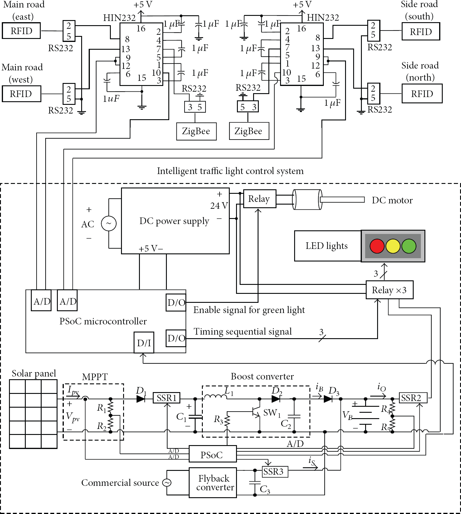
The circuit system of the hardware interface.
This study used traffic flow data generated using RFID, which was then transmitted through RS232 to PSoC. Because PSoC voltage is rated at 5 V, while RS232 output voltage is rated at 12 V, the RS232 output voltage was thus lowered to 5 V through an HIN232 chip before data transmission into PSoC. The internal digital to analog (D/A) converter of PSoC converts the data signal output to 5 V before it is sent to the intelligent traffic signal control system. The correlation grade calculated using the extension algorithm can be used to observe different types of relationships and for fine tuning the traffic signal time sequence. It results in the multiple segment control of traffic flow. The power system is the main feature that differs from the present conventional traffic light system. The developed system is powered from a photovoltaic module and commercial source. The system can be categorized as (i) solar panel; (ii) maximum power tracker; (iii) commercial source; and (iv) battery charger. In sufficient solar irradiation condition, solid-state relays SSR1 and SSR2 are switched on to convert solar power into electricity to charge the battery and then supplies power to the LED traffic light each day. Under low insolation or at night, the SSR3 is switched on and commercial source supplies power with solar panel to charge the battery. To protect the battery from over charging and over discharging, a PSoC is used for charging and discharging control. The battery acts as an immediate power storage and power storage buffer device. A PSoC is also used to control the mechanical experimental evaluation system and the real-time traffic light control based on the proposed extension method.
4. Intelligent Control of Traffic Flow
This section describes the method of applying extension theory to traffic flow control systems. Extension theory was first proposed by Professor Cai Wen in 1983 [17], which is a method of studying the extension and regularity of objects. The method is designed to deal with contradictory problems that can be quantified into digital data for processing by computer.
4.1. Extension Theory
The process of using computers to solve contradictory problems requires the use of extension method to establish a corresponding quantitative tool. The basis of extension mathematics is the extension set theory [17, 18], which includes the extension set, correlation function, and their relationship to extension mathematics. In terms of classical mathematics, the process of solving problems still requires the construction of a mathematical model [19, 20]. Extension mathematics is no exception. A matter element model is used in the extension mathematical model, which is defined in the following:

In matter element theory, matter element R can also be a multidimensional matter element. In a matter element array, there is the characteristic vector

However, each corresponding value can be either a point or a range. If it is a range, it is called a classical region and is included in a neighboring region. For example, if the length of a neighboring region is (0, +∞), then the length of a piece of paper (0, 50 m) represents the length of a classical region within the length of a neighboring region.
4.2. Correlation Function
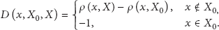
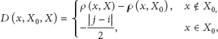
When the element of an extension set is a matter element, it becomes a matter element extension set. Value and quantity are studied together to quantitatively describe the changing relationship between an object and its attributes. To establish the calculation equation on the real axis of the correlation function, the concept of the range of distance as a real variable is extended as “distance”. In a correlation function, the concept of distance is expressed in the real domain (−∞, +∞). If x is a point within a certain interval

The difference in the concept of distance between the classical mathematical thought and the extension thought is that distance in classical mathematics refers to the distance d from point x to interval
The solving of the problem not only involves the consideration of the positional relationships of points inside the interval, but also between two different intervals, which can be described using rank value. Assume that there are two intervals
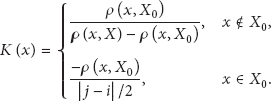
Having acquired the concept of distance and rank value, the correlation function, which is distance divided by rank value, is shown in (5) and drawn in Figure 3 as a curve diagram. Consider the following:


Correlation function curve.
Figure 3 shows that if
4.3. Establishment of an Extension Matter Element Model
In this study, traffic flow data collected from RFIDs installed at road intersections are divided into three traffic parameters.
Flow: the number of vehicles passing through within a period of time, which is used to better understand the operating conditions of road sections. Speed: the time it takes for single vehicles to pass by the detector, which is used to better understand the average speed of road sections. Occupancy: the amount of traffic flowing through the detector at various times, which is used to better understand the vehicle density conditions of road sections.
Because occupancy can be better understood through the parameters of flow and speed, this study used speed and occupancy as characteristics for the matter element model. Thus, the matter element model for the traffic flow is defined in the following:
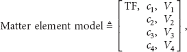
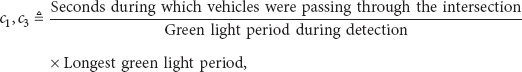

Equation (7) is used to calculate the maximum number of seconds under various green light periods to glean information about the speed of vehicles. The faster the speed, the shorter the time it takes for a vehicle to pass through, which indicates low traffic flow at that moment. Equation (8) is designed to calculate occupancy rate, such that the higher the value, the higher the traffic flow it represents at that moment, with a higher potential for traffic congestion. Here, the traffic flow is divided into high, moderate, and low rates that when combined with the corresponding main roads and side roads, are used to establish nine types of flow conditions; namely,
TF1: main road and side road traffic flow are high; TF2: main road traffic flow is high, and side road traffic flow is moderate; TF3: main road traffic flow is high, and side road traffic flow is low; TF4: main road traffic flow is moderate, and side road traffic flow is high; TF5: main road and side road traffic flow are moderate; TF6: main road traffic flow is moderate, and side road traffic flow is low; TF7: main road traffic flow is low, and side road traffic flow is high; TF8: main road traffic flow is low, and side road traffic flow is moderate; TF9: main road and side road traffic flow are low.
An RFID sensor is used to collect data on the quantity of traffic passing through the detector and records the number of vehicles passing through the intersection and the amount of time it took for all vehicles to pass through the intersection when the signal light is green, which is tested using different lengths of time for the green light. After the characteristic values are calculated using (7) and (8), the recorded data are organized to construct various categories of classical and neighboring regions in the matter element model. The nine categories of the classical region in the matter element model are listed in Table 1. As for the neighboring region, it is constructed using the maximum and the minimum values of all the various types of the classical region. To avoid calculation error in digits by (4) at the endpoint, a value 0.1 is added to the maximum value and subtracted from the minimum value before expressing it using the following:

The extension matter element model of traffic flow.

5. Experimental Results
5.1. Simulation System of Traffic Light Control
We adopted a mechanical experimental evaluation system because we intended to test the viability and accuracy of the passive RFID system and the ZigBee wireless module and their respective communication interfaces and not only test the viability of the application of the proposed extension evaluation method for traffic flow control. Therefore, using models of traffic flows available, for example, in simulation of urban mobility (SUMO) for simulation and testing cannot verify the viability of the entire system. A schematic diagram of the traffic simulation system was constructed to verify the feasibility of a traffic signal control system based on RFID/ZigBee wireless network communication, which is shown in Figure 4. Acrylic was then used to construct a model to simulate an intersection, with small LED lights placed at the intersection to model the traffic signal lights. RFID was added to the front of the model signal lights to monitor traffic at the intersection. After the collected data was transmitted to PSoC, ZigBee was activated to remotely monitor the traffic flow. The flow of vehicles was simulated using a model of a moving track driven by a DC motor-shaft driven belt, and pieces of Velcro were taped to the belt at various locations before small model cars were stuck on them. When the motor began to run, it drove the belt which moved the drive lane, causing the model cars to move. The number of model cars could be added this way to achieve the required traffic flow density, with the actual traffic control diagram shown in Figure 5.

Simulation system scheme of traffic signal light control.

Physical development of traffic signal flow control simulation system.
5.2. Intelligent Traffic Flow Control System
The extension matter element model was constructed to verify the feasibility of the proposed technological method for determining traffic flow, in which the intelligent traffic control system must be able to fine-tune the number of seconds that the signal light stays green, to adapt to various traffic flow conditions. Of course, in using the extension method, identification results from correlation degree and extension distance can similarly be used to calculate the representative green light period. Thus, the extension method was used to make decisions on the period during which the light is green for the control of traffic flow.
When using ZigBee for remote real-time monitoring, the direction of the intersection and vehicle ID can be displayed directly on the computer screen, as shown in Figure 6.

Screen display of computer monitoring of vehicles passing the intersection.
The control program required for determining traffic flow in extension mathematics is as follows.
Step 1.
Create a classical region for the extension matter element model of each traffic flow category and neighboring region of (9).
Step 2.
Read the information on each characteristic value obtained from traffic flow measurements.
Step 3.
Calculate the value of the correlation function of traffic flow to obtain the correlation degree for each category of traffic flow, with a maximum value of the correlation degree equal to 1. Thus (4) is revised to
Step 4.
Set the weight coefficients
Step 5.
Calculate the level of correlation of each traffic flow, as shown in the following:

Step 6.
Determine the traffic flow category using the maximum correlation value of individual category, the decision equation of which is as in the following:

If the primary traffic flow category is determined to be 
The basic number of seconds in traffic flow was divided into high, moderate, and low traffic flow, with corresponding green light time periods divided into 

Test data for traffic flow decision using the proposed extension method.

Results of traffic flow category identification using the proposed extension method.

The above description clearly shows that calculation of correlation degree can effectively adjust the number of seconds in the green light interval of the traffic signal under different traffic flow conditions, which can also be fine-tuned.
To show that the extension evaluation method is excellent, the performance of the extension evaluation method was compared with those of particle swarm optimization (PSO), genetic algorithm (GA), and evolutionary programming (EP) algorithms under the condition of high traffic flow (i.e., when 10 vehicles pass through main roads, 10 vehicles pass through side roads, and the green light period lasts for 25 seconds; that is,
Traffic flow control performance obtained using the PSO, GA, EP, and the proposed extension methods.

6. Conclusions
The traffic signal control system proposed in this study, which is based on RFID and ZigBee wireless network communication, possesses accurate traffic flow detection and remote wireless transmission capabilities. The data collected from the detected traffic flow is divided into the number of vehicles and the number of seconds for vehicles to pass through during the green light interval, which is transmitted to a PSoC. The category of traffic flow at the period that vehicles pass through the intersection is determined using extension mathematics, and the timing of the corresponding traffic signal is further adjusted for control of the actual traffic flow.
Footnotes
Conflict of Interests
The authors declare that there is no conflict of interests regarding the publication of this paper.