
Abstract
The leakage flow paths in the sidewall gaps of centrifugal pumps are of significant importance for numbers of effects. The paper is concerned with the transient flow in the leakage flow paths with wear ring clearance variation. For this purpose, numerical simulations of the whole pump were carried out. The grid dependence and yplus check were performed first. Additionally, experimental data of performance characteristic and pressure fluctuation inside the sidewall gap was used to validate the numerical results. The transient velocity fields inside the sidewall gaps during one blade passage period were simulated. And the leakage through the wear ring gap was obtained for all operating points investigated. To have a better idea of attenuation and propagation of pressure inside the sidewall gap, the unsteady pressure distributions in the gap were calculated. Additionally, the surfaces of the impeller were divided into four parts. The fluid force on each part was expressed as a percentage of the total radial force. Through comparing the flow fields, the pressure distributions, and the radial force between the pumps with different wear ring clearances, the effects of the wear ring clearance were discussed in detail. The results can be used to guide the optimum design of the pump sidewall gaps.
1. Introduction
Leakage flow paths between the rotating impeller and the stationary housing play an important role in centrifugal pumps. The gaps in the leakage flow paths can greatly affect pump performance. A larger gap size can decrease the disk friction and hence increase the leakage flow rate, according to the study conducted by Gulich [1]. Also, increasing the length and surface roughness of the gap clearance will increase the pump losses and reduce the leakage flow rate [2]. The swirling flow and nonuniform pressure distribution induced by the leakage in the sidewall gaps are the main sources of the radial force [3]. Uy and Brennen [4] and Adkins and Brennen [5] indicated that the leakage flow from the impeller outlet to the front sidewall gap can produce great hydraulic forces, which can take up 70 percent of the total radial force and 30 percent of the total tangential force. Guinzburg et al. [6] investigated the influence of the gap size between the shroud and the casing on the hydraulic force, and the results show that the decreasing leakage gap size can increase the force. Hsu and Brennen [7] presented the effect of swirl at the leakage path inlet on unsteady hydraulic force, which indicated that the increasing swirl can make the forces unstable.
Recent years, CFD was used to study the hydraulic forces and pressure pulsations in centrifugal pumps. Majidi [8], Solis et al. [9], and Barrio et al. [10] calculated the radial force and pressure fluctuations in centrifugal pump but without the leakage flow paths being considered. However, the leakage flow paths are of significant importance for numbers of effects; they must be included in CFD calculations. Several authors have included the leakage flow paths in their calculations [11–13].
Since the wear ring clearance gap is an important part of the leakage flow paths in centrifugal pumps, it is necessary to pay enough attention to its influence. Increasing wear ring clearance can decrease pump head and efficiency, as illustrated in studies conducted by Chen et al. [14], Zhao et al. [15], and Wenguang [16]. Additionally, a strong hydraulic force can be developed when the impeller has a whirling motion in the housing [3]. This effect was known as the Lomakin effect [17]. The effect was well studied both experimentally [18, 19] and numerically [20, 21].
The main goal of the paper was to study the influence of the wear ring clearance gap on the transient flow in the pump. For this purpose, the wear ring clearance was changed from 0.1 mm to 1.0 mm with the other geometry parameters remaining the same. The commercial code CFX was used to solve the transient flow in the whole pump under seven flow rates ranging from 20% to 140% of the rated flow rate. The whole pump included the leakage flow path, the impeller, and the volute as well as the inlet domain. Structured grids were generated for the whole geometry. And the grid dependence and y+ check were performed firstly. Additionally, the experimental data of the pump performance characteristic and pressure fluctuations inside the sidewall gap were used to validate the numerical results. Once validated, the internal flow and pressure pulsations as well as unsteady radial force were calculated by the numerical code as a function of the wear ring clearance.
2. Numerical Model and Methodology
The focus of this study was a centrifugal pump with single suction and single volute, with a shrouded impeller. The impeller is designed to operate at 2900 rpm. The designed flow rate is 50 m3/h, and the designed head is 30 m. The wear ring clearance changes from 0.1 mm to 1 mm, with the other geometric parameters staying the same. General pump geometric values are identified in Table 1.
Main pump parameters.

A CAD model was generated first, and then the model was discretized into mesh by using the code GridPro 5.1. The mesh is of high quality structured grids which was divided into four parts: (i) inlet domain, (ii) impeller, (iii) volute and outlet duct, and (iv) leakage flow domain. Each of the parts was built and meshed independently. As the impeller (ii) has a relative rotation with respect to the three other parts, six surfaces were created as interfaces between (i)–(iv) and (iii)-(iv) as well as (ii)–(iv). Figure 1 presents a detail of the mesh and the interfaces of the pump. In Figure 1, the surfaces A and F were created as interfaces between the inlet domain-leakage flow domain and the leakage flow domain-volute and outlet duct. The surfaces B, C, D, and E were used as interfaces between the leakage flow domain and the impeller.
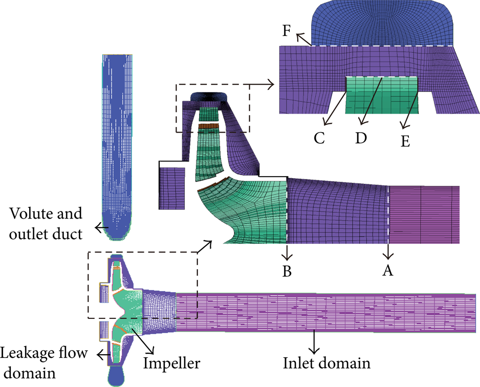
Some details of pump mesh and interfaces.
The commercial software CFX was applied to solve the transient fully 3D Reynolds-averaged Navier-Stokes equations in the whole pump. In order to simulate the rotational effect, the multiple frames of reference were involved. The impeller part (ii) was set in the rotational frame of reference, and the inlet domain (i) and volute and outlet duct (iii) as well as the leakage flow domain (iv) were set in the stationary frame of reference. The grid interfaces between two stationary components were set as general grid interface (GGI). Between the rotational and stationary components GGI was also used as internal component connection, and the Rotor/stator interface was applied in transient analysis, while the frozen rotor interface was used in steady state analysis.
The boundary conditions imposed were a constant total pressure (1 atm) at the inlet of the inlet domain (i) and a mass flow rate at the outlet of the volute and outlet duct (iii). The reference pressure was set to 0 Pa. All walls of the flow domain were modeled using a no-slip boundary condition. A second-order high resolution discretization was used for the advection terms and a second-order backward Euler scheme for the transient terms.
Turbulence was simulated with a k-ω SST model, which is considered as a good compromise between accuracy and computational effort even for the impeller sidewall gaps [22]. The standard wall function was used to calculate boundary layer variables. In order to simulate the turbulence effect in the boundary layer, the grid node of the first cell-layer away from all the walls was specified to be 2 E − 5 m. The detail mesh is shown in Figure 2. The reported magnitude of y+ of the surfaces is shown in Figure 3. In Figure 3, y+ on the impeller and volute surfaces is well below 16.

Details of mesh on impeller walls (a), volute walls near tongue (b), and walls of leakage flow domain (c).

y+ distribution on the impeller and volute.
The transient calculations were initialized from the steady solutions; the number of time steps for each blade passage was set to N = 36. This resulted in a time step size of Δt = 1.15E − 4 s, which corresponded to 180 time steps per revolution. The average residual convergence criterion was set to be 1E − 5. The CFD results were recorded after five impeller revolutions performed to achieve a stabilized solution. The simulations in this study were carried out on a cluster of twelve Intel Xeon 5600 nodes.
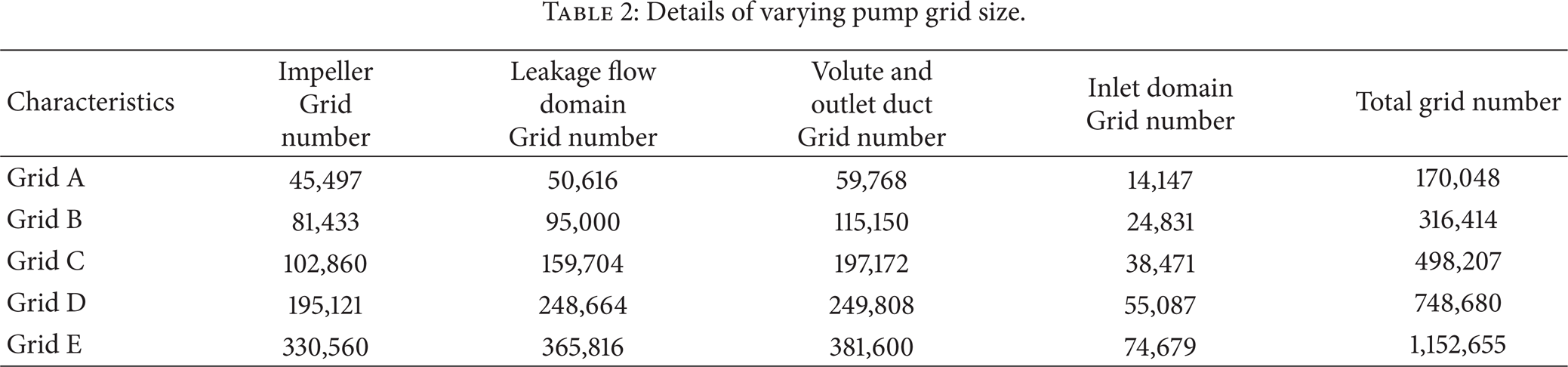
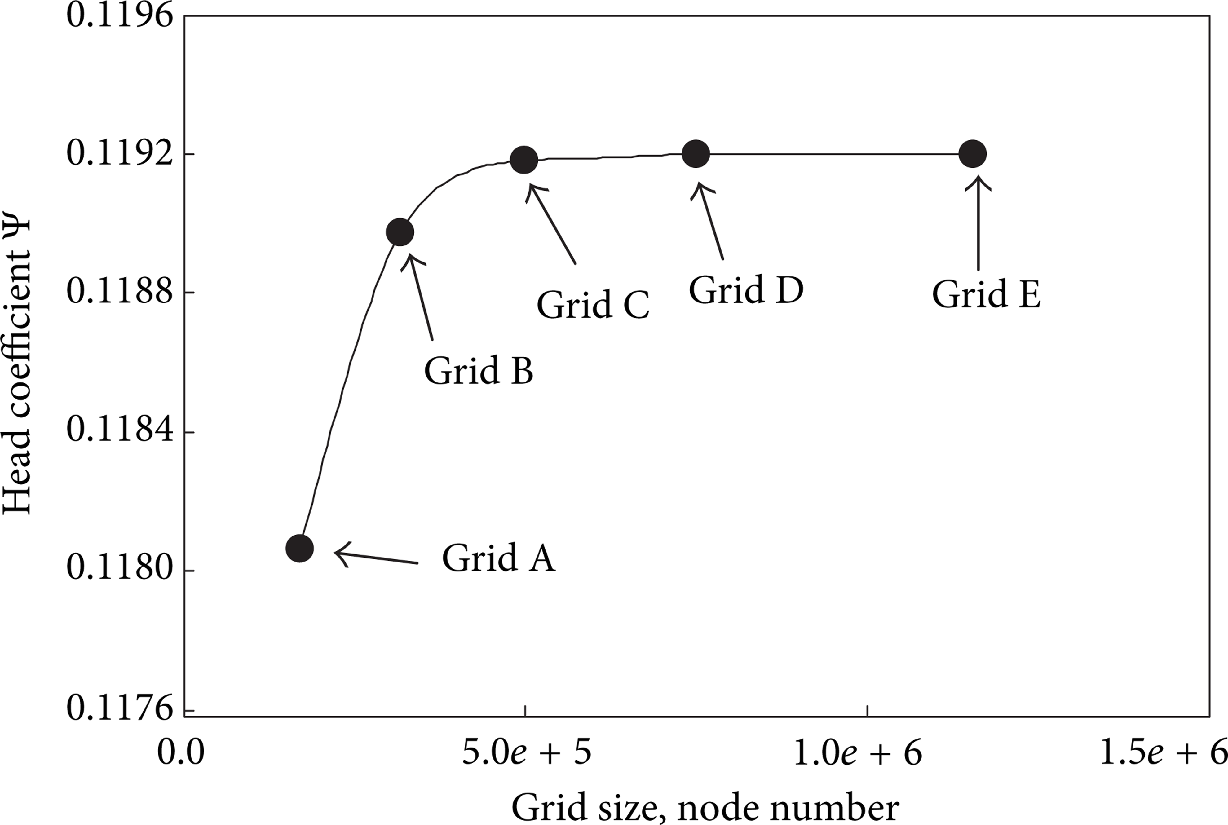
The grid dependence study was carried out through five grid topologies, named Grid A, Grid B, Grid C, Grid D, and Grid E. The details of varying grid sizes are shown in Table 2. The pump head at the design condition was taken as the parameter to determine the influence of the mesh size on the solution. In Figure 4, it can be observed that the pump head coefficient reaches an asymptotic value as the number of grids increases. According to this figure, Grid D is considered to be reliable to ensure the grid independence.
Details of varying pump grid size.
Influence of gird size on pump head.
In order to study the unsteady flow in the pump, two coordinates were built as shown in Figure 5. One was a coordinate used for defining blade position marked as (x,y) and the other marked as (x′,y′) was for defining the circumferential position in the stationary parts. In the coordinate (x,y), one blade was chosen as a reference, and the line through the trailing edge of this blade and the rotating center was defined as axis-x, and the line passing the center and the tongue of the volute was defined as axis-y. The axis-x rotates with the blade, with the axis-y remaining stationary. The relative angle between x and y in clockwise direction was defined as φ. When the trailing edge of the reference blade was just passing the tongue, the value of φ was 0. The axes x′ and y′ in the coordinate (x′,y′) were both stationary, and the circumferential position was defined by using the angle θ. The angle θ increases along clockwise direction, and θ = 0 when x′ = 0 and y′ > 0. To capture the pulsating pressure in the sidewall gaps, two virtual lines formed by various monitoring points were created in the sidewall gaps (red line for the front sidewall gap and blue line for the rear sidewall gap), as shown in Figure 5. In order to verify the numerical results, during the experiments a pressure tap was located in the front sidewall gap, as shown in Figure 5.

Coordinate definition (a) and location of monitoring points (b).
3. Experimental Validation
The numerical results were validated by means of measurements of pump performance characteristics and unsteady pressure fluctuations. The experiments were carried out in a close hydraulic rig, as shown in Figure 6. The pump in the rig was driven at a constant speed of 2900 r/min by a variator, with a blade passing frequency of fBP = 242 Hz. The torque was measured through a Hall-effect sensor. In the rig, the flow rate was controlled by a flow valve installed downstream on the outlet pipe, and the flow rate was measured by a turbine flow meter. The mean static pressure was tested through two piezoresistive pressure sensors installed at the inlet and outlet of the pump. The measuring ranges of the sensors were −100 kPa~100 kPa and 0~600 kPa, respectively. A transient pressure sensor (PPM-T127C from CSPPM Co. Ltd., China) with the sensitivity of 12.5 mv/KPa was used and mounted on the pressure tap (see Figure 5) to monitor the pulsating pressure in the front sidewall gap. A PXI-6251 data acquisition module was applied to capture the electric signals and convert them to digital signals. The data was finally analyzed by using the code LabVIEW in a computer.

A close hydraulic test rig.
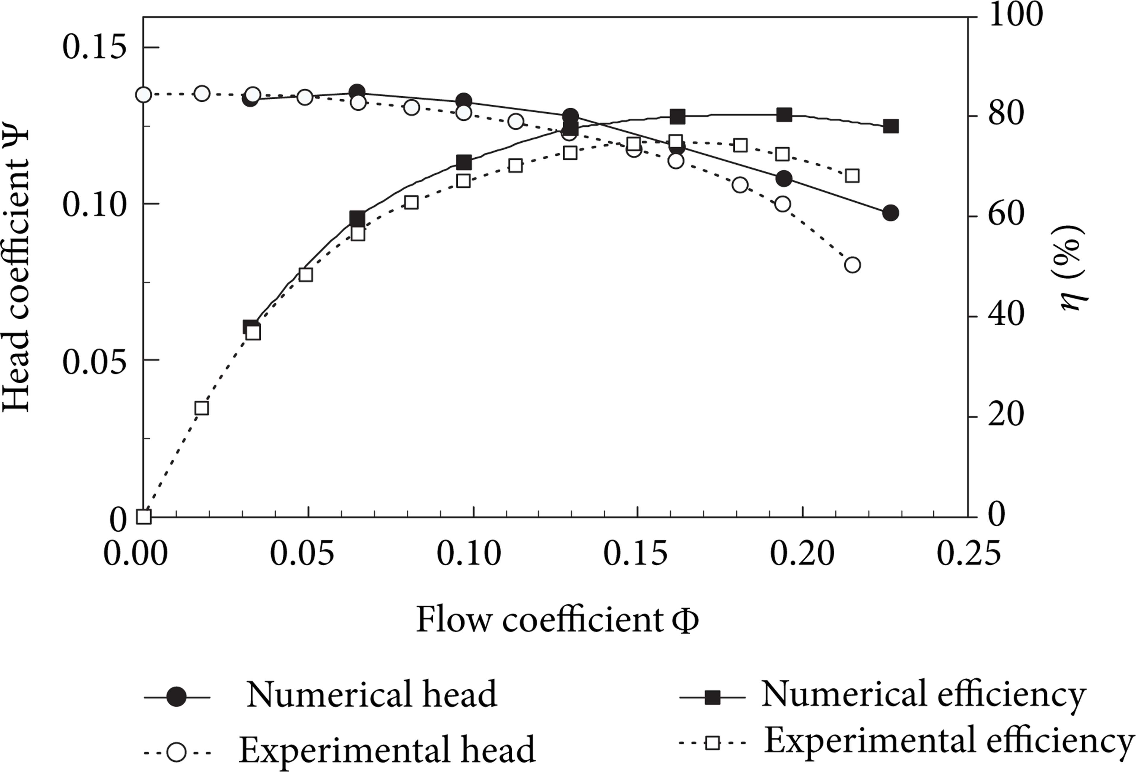
Figure 7 presents the experimental performance characteristics and the numerical predictions. It can be seen in Figure 7 that there is a general good agreement between the experiments and the predictions. At the low and medium flow rates the relative differences between experimental and numerical pump head characteristic remain below 4.5%. However, at the large flow rates the relative differences become big, because at this flow rate the cavitation occurred, and its effect was not considered in the CFD calculation in this study. Also, it can be seen in Figure 7 that the efficiency characteristics predicted are close to the experimental results at the low and medium flow rates, and big differences can be observed at the large flow rates because of the cavitation.
Performance curves of the pump obtained experimentally and numerically.
The transient CFD predictions were also validated by the unsteady pressure fluctuation inside the front sidewall gap. Figure 8 presents the numerical and experimental pressure pulsations during an impeller revolution at the design flow rate. Although the numerical pressure is not always the same at the same time as the experimental data, it can be observed in Figure 9 that the comparison between the numerical results and experimental data shows a quite good agreement.
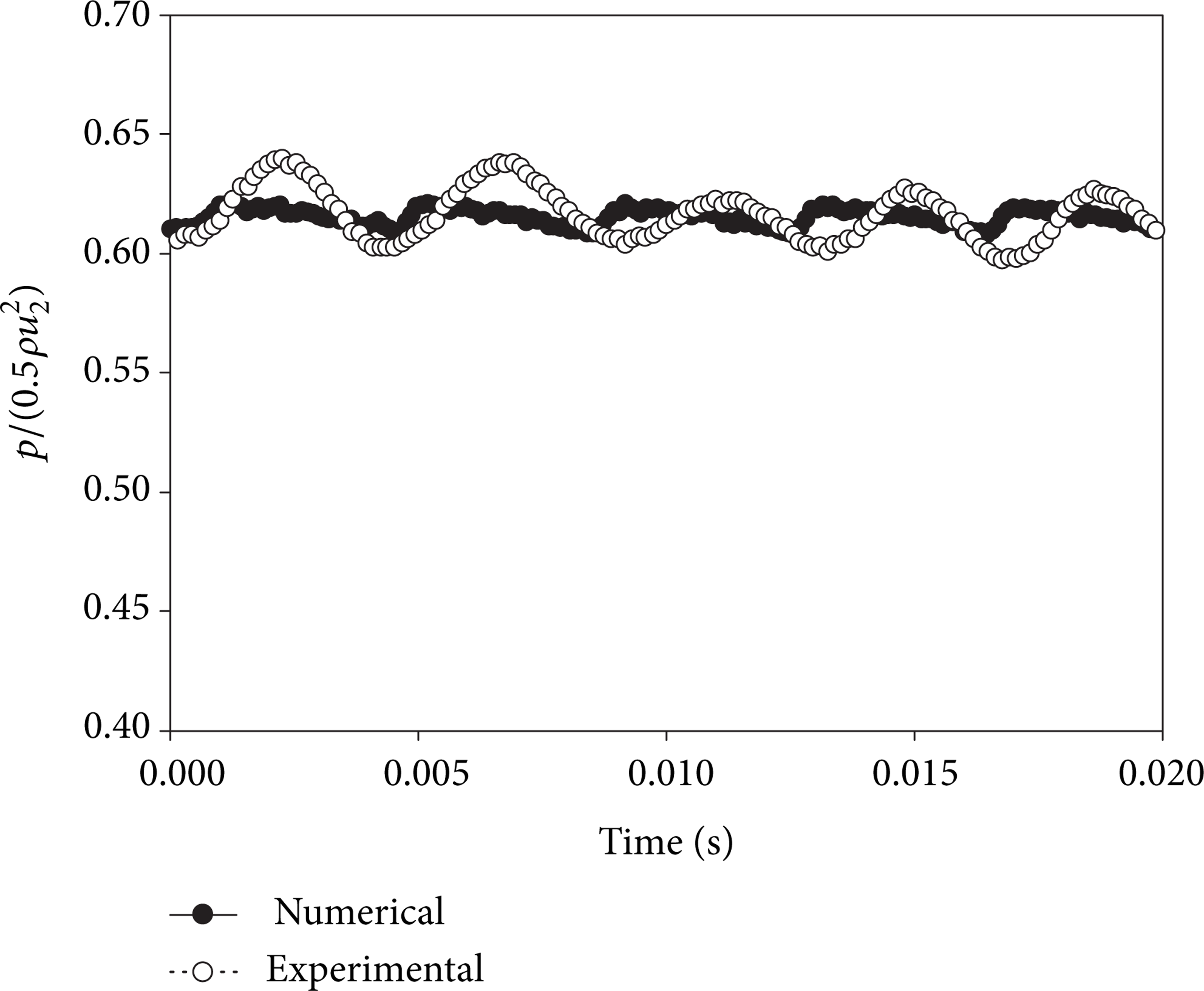
Pressure fluctuation inside the front sidewall gap at the design condition.

Vectors of velocity for wear ring clearance e = 0.2 mm during one single blade passage period (Q/Q N = 1.0): (a) numerical results for φ = 0°; (b) numerical results for φ = 24°; (c) numerical results for φ = 48°.
4. Results and Analysis
Once the numerical results were validated, the numerical model was used to investigate the pressure fluctuations and velocity fields in the sidewall gaps. And also the unsteady radial force was studied with wear ring clearance variation. In this study only the wear ring clearance was changed, and the other geometric parameters remained the same, as listed in Table 1.
4.1. Unsteady Flow Fields in the Sidewall Gaps
The velocity fields in the sidewall gaps during one single blade passage period for the wear ring clearances e = 0.2 mm, e = 0.6 mm, and e = 1.0 mm are presented in Figures 9, 10, and 11, respectively. According to Figure 9, the fluid in the rotating boundary layer inside the sidewall gaps is transported radially outwards by the centrifugal forces; for reasons of continuity, fluid flows back radially inwards along the casing wall; then a core flow is formed in the sidewall gaps. Obviously, the fluid field inside the front sidewall gap has a time periodic pattern, while the flow field inside the rear sidewall gap almost remains the same. That is because a leakage is always present in the front sidewall gap, but in the rear sidewall gap the leakage is zero because of the shaft seal. The leakage carries an angular momentum from the volute casing into the front sidewall gap and enhances the fluid rotation. For blade position φ = 0°, the fluid flowing inwards along the front casing wall is of low velocity. As the blades rotate to the position φ = 24°, the velocity is increased. But when the blades get to the position φ = 48°, the velocity of the fluid along the front casing wall is decreased. This indicates that the velocity along the front casing wall varies with time, which introduces a time-varying flow pattern in the front sidewall gap. Comparing the three Figures in Figure 9, it can be observed that the velocity distribution at the impeller outlet has an effect on the inlet boundary condition for the flow through the front sidewall gap. The flow in the front sidewall gap is coupled to the main flow at the impeller outlet by exchange of momentum through the leakage, which can accelerate or retard the fluid rotation in the gap.

Vectors of velocity for wear ring clearance e = 0.6 mm during one single blade passage period (Q/Q N = 1.0): (a) numerical results for φ = 0°; (b) numerical results for φ = 24°; (c) numerical results for φ = 48°.

Vectors of velocity for wear ring clearance e = 1.0 mm during one single blade passage period (Q/Q N = 1.0): (a) numerical results for φ = 0°; (b) numerical results for φ = 24°; (c) numerical results for φ = 48°.
Through comparing Figures 9, 10, and 11, it can be concluded that the flow patterns remain the same as for wear ring clearance e = 0.2 mm except that the overall velocity magnitude level varies according to the wear ring clearance. It can be observed that the velocity in the front sidewall gap gets increased with increasing wear ring clearance. This is because the leakage is increased with increasing clearance, according to Figure 12. In Figure 12, the leakage is nondimensionalized with respect to the design flow rate. A continuous reduction of the leakage is apparent when the pump flow rate increases. Also an appreciable rise is visible when the wear ring clearance increases. And the rate of rise is decreased with increasing wear ring clearance according to Figure 12. Due to the increased leakage, the velocity magnitude in the front sidewall gap is increased and the pressure would be decreased at the same time.
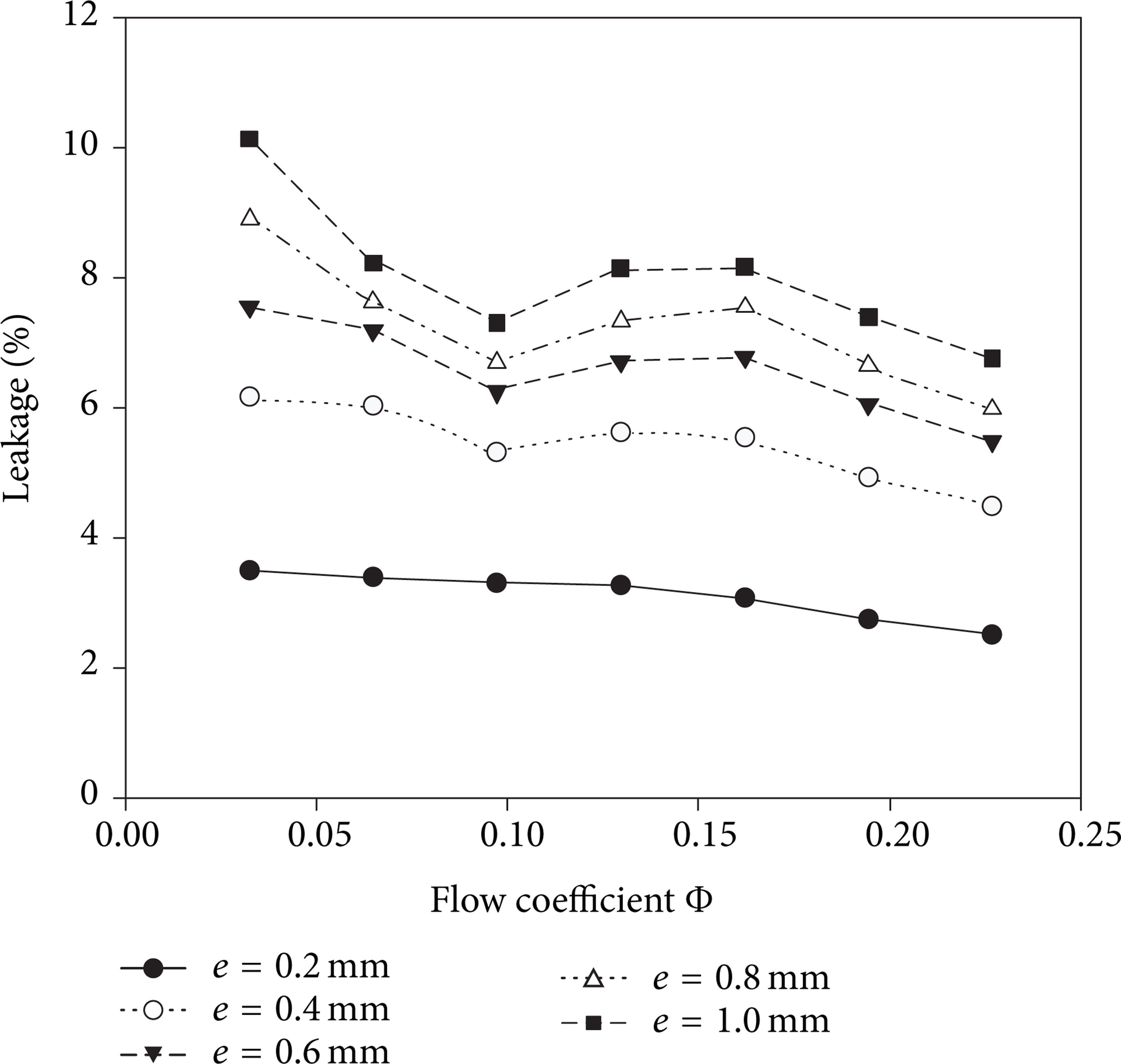
Leakage as a function of the flow rates.
4.2. Unsteady Pressure Distributions in the Sidewall Gaps
4.2.1. Results under Design Flow Condition
The static pressure inside the sidewall gaps along the virtual lines (see Figure 5) was obtained through the CFD calculations. Figure 13 presents the comparisons of the static pressure distribution inside the sidewall gaps between different wear ring clearances. It can be seen from Figure 13(a), in the front sidewall gap, that the static pressure distribution changes greatly with the clearance. It increases with the decreasing wear ring clearance. However, in the rear sidewall gap, as shown in Figure 13(b), no significant difference is present. For the rear sidewall gap, the leakage is zero. As a result, the wear ring gap has much less effect on the flow since the axial flow component diminishes. The comparisons between the pressure distributions inside the front and rear sidewall gaps indicate that the influence of the leakage flow on the pressure distribution is much stronger in the front sidewall gap.

Comparisons of static pressure distributions inside the front sidewall gap (a) and the rear sidewall gap (b) with wear ring clearance variation under the design flow condition.
To have a better idea of attenuation and propagation of pressure fluctuations inside the front sidewall gaps, the data of pulsating pressure along the virtual line was collected during an impeller revolution. Figure 14 shows the unsteady pressure distribution inside the front sidewall gap. The coordinate in x represents the radius along the virtual line nondimensionalized with respect to the impeller radius. The y-coordinate corresponds to the angle of rotating blades during an impeller revolution. The comparison between the three different wear ring clearances shows that an appreciable reduction of the pressure fluctuations between e = 0.2 mm and e = 0.6 mm is obvious. No significant decrease is observed between e = 0.6 mm and e = 1.0 mm. This indicates that the reduction gradient of the pressure fluctuation in the front sidewall gap decreases with increasing wear ring clearance. This is related to the relationship between the rate of change of the leakage and the wear ring clearance. As mentioned in Figure 12, the rate of rise of the leakage decreases with increasing wear ring clearance, which causes the change of pressure much less with increasing wear ring clearance. Also, a time periodic pattern for all geometries is clearly visible during an impeller revolution.

Contours of normalized pressure fluctuations inside the front sidewall gap with different wear ring clearances (Q/Q N = 1.0): (a) numerical results for wear ring clearance e = 0.2 mm; (b) numerical results for wear ring clearance e = 0.6 mm; (c) numerical results for wear ring clearance e = 1.0 mm.
4.2.2. Results for Off-Design Conditions
The unsteady pressure diagrams for part load and overload conditions are shown in Figures 15 and 16. It can be concluded that the basic relationships remain the same as for the design flow rate except that the overall pressure level varies according to the operating point. According to Figure 15, for the part load condition, the reduction of the pressure fluctuations with increasing wear ring clearance is more obvious compared with the design flow rate. For the overload point, the reduction is not clearly visible as the same with the design point, according to Figure 16. Also the pressure fluctuation increases with increasing radius along the virtual line inside the front sidewall gap in case of off-design conditions.

Contours of normalized pressure fluctuations inside the front sidewall gap with different wear ring clearances (Q/Q N = 1.0): (a) numerical results for wear ring clearance e = 0.2 mm; (b) numerical results for wear ring clearance e = 0.6 mm; (c) numerical results for wear ring clearance e = 1.0 mm.

Contours of normalized pressure fluctuations inside the front sidewall gap with different wear ring clearances (Q/Q N = 1.0): (a) numerical results for wear ring clearance e = 0.2 mm; (b) numerical results for wear ring clearance e = 0.6 mm; (c) numerical results for wear ring clearance e = 1.0 mm.
4.3. Unsteady Radial Force
The transient radial load on the impeller during an impeller revolution for seven flow rates is presented in Figure 17. According to this figure, the radial force changes from the second quadrant to the fourth with increasing flow rates. It reaches its minimum at the design flow rate, while it rises at the off-design conditions. The force increases with growing flow rate for the overload condition and increases with decreasing flow rates for the part load conditions. The time-average radial force is presented as function of the flow rates, as shown in Figure 18. At the design condition, the force is of very low magnitude compared with the off-design points. As such the change of force with the wear ring clearance is not clearly visible at the design condition. But for the off-design conditions, it can be observed that the time-averaged value of the force rises with increasing wear ring clearance.

Radial force on the impeller for seven flow rates.

Time-averaged radial force as a function of the flow rates.
To have a better idea of the influence of the wear ring clearance on the radial force, the surfaces of the impeller are divided into four parts. As shown in Figure 19, the four parts include the boundary surfaces of wear ring clearance (with green color), the surfaces of the front shroud wall (with yellow color), the surfaces of the rear shroud wall (with blue color), and the inner surfaces of the impeller (with red color). The force on each part is expressed as a percentage of the total radial force acting on the impeller. Figure 20 presents the force on these separated parts at the design condition.

Four parts of the impeller.

Unsteady radial force acting on the separated parts of the impeller during an impeller revolution.
According to Figures 20(a) and 20(b), the sum of the forces created in the wear ring clearance and in the front sidewall gap takes up more than 60% of the total radial force. Therefore, small percentage is occupied by the forces generated in the rear sidewall gap and inside the impeller. This indicates that the wear ring clearance and the front sidewall gap have more important effect on the safe operation of the pump. According to Figure 20(a), the reduction of the fluid force with increasing wear ring clearance is obvious. However, the reduction will be small when the clearance exceeds a certain value. This is because high pressure will be created in the narrow gap when the wear ring clearance is very small. When the clearance increases, the leakage rises quickly and a huge reduction of pressure is obtained as a result. If the clearance keeps increasing, the rise of the leakage will be very little according to Figure 12, and therefore no significant change of pressure or the force will be observed. It can be observed in Figure 20(b), a continuous growth of the force created in the front sidewall gap is apparent when the wear ring clearance increases. Also the rate of the growth gets small when the clearance exceeds a certain value, which is similar to the force created in the wear ring gap. According to Figures 20(c) and 20(d), it can be concluded that the wear ring clearance has little impact on the fluid force created in the rear sidewall gap and inside the impeller.
5. Conclusion
The transient flow in a centrifugal pump with various wear ring clearances was studied. The wear ring clearance was changed from 0.1 mm to 1.0 mm with the other geometry parameters remaining the same. Structured grids were generated for the whole pump geometry. The grid dependence and y+ check were performed first. Experimental data of performance characteristic and pressure fluctuations inside the sidewall gap was used to validate the numerical results. The comparisons between numerical predictions and experimental data show good agreement, which indicates that the CFD method in the paper could be used to predict the internal transient flow in the pump. The analysis of the results gives the following conclusions.
The transient velocity fields inside the sidewall gaps during one blade passage period are studied. The results indicate that the unsteady flow in the front sidewall gap is strongly coupled to the main flow at the impeller outlet. And the magnitude of the velocity in the front sidewall gap clearly depends on the value of the wear ring clearance. However, the results in the rear sidewall gap show that the flow is independent of both the time and the wear ring clearance because of zero leakage through the rear sidewall gap.
The unsteady pressure distribution inside the front sidewall gap is found to be very dependent on both the wear ring clearance and the radial position, with maximum pressure fluctuations for part load conditions. However, the pressure distribution in the rear sidewall gap is found to be independent of the wear ring clearance. Thus, the results of the pressure distributions inside the sidewall gaps indicate that influence of the leakage flow on the pressure distributions is much stronger in the front sidewall gap.
The results of the fluid force indicate that the force created in the wear ring gap and the front sidewall gap contributes more than 60% or 70% to the total radial force acting on the impeller. And the fluid forces created in the two gaps are found to be very dependent on the wear ring clearance. Thus, the fluid force created in the wear ring gap decreases with increasing clearance, and little change is obtained when the clearance exceeds a certain value. In addition, a continuous growth of the force created in the front sidewall gap is apparent when the clearance increases.
Footnotes
Nomenclature
Conflict of Interests
All authors declare no conflict of interests. The supports of the National Natural Science project of China titled “Multi-condition hydraulic design of centrifugal pumps based on environment recognition memory methods” (nos. 51109095 and 51209105) and the Jiangsu Province project titled “Coarse particles clogging mechanism in pumping system” (no. CXZZ13_0675) have no conflict of interests.
Acknowledgments
The authors gratefully acknowledge the support from the National Natural Science project of China titled “Multi-condition hydraulic design of centrifugal pumps based on environment recognition memory methods” (nos. 51109095 and 51209105) and the Jiangsu Province project titled “Coarse particles clogging mechanism in pumping system” (no. CXZZ13_0675).