
Abstract
Energy efficiency is one of the most important issues for operations of wireless sensor networks. To increase network lifetime and to reduce energy consumption of sensor nodes, many clustering and routing protocols have been studied. In this paper, we propose an energy-efficient cooperative communication method which forms clusters and establishes intercluster routes directly or via relay nodes. Relay nodes selected by the cooperation of adjacent cluster heads along with their cluster members can prevent long-haul transmissions of cluster heads. This can reduce the energy consumption of cluster heads. We show the validity of using relay nodes and then compare the performance of the proposed method with that of a well-known clustering and routing protocol for wireless sensor networks. Our computational experiments demonstrate that network lifetime, energy consumption, and scalability of the proposed method are better than those of the compared method.
1. Introduction
A wireless sensor network (WSN) consists of a large number of wireless sensor nodes, which obtain data from the near environment and then transmit the information to the external base station (BS) directly or via multihop [1]. Wireless sensor nodes have many constraints which differ from other wireless networks [2, 3]. A wireless sensor node is constrained in terms of its processing capability and storage capacity. Furthermore, its critical weakness is that the power device cannot be recharged or replaced. Therefore, energy efficiency is very important in WSNs [4].
To raise the energy efficiency of WSNs, many routing protocols have been developed, such as flat routing, cluster-based routing, and location-based routing. Most of the routing protocols utilize a distributed or self-organizing method. The cluster-based routing is the most energy-efficient routing protocol among them. It divides a WSN into several clusters, which are comprised of a “cluster head” (CH) and many “cluster members” (CMs). To reduce the transmission energy consumption, CMs transmit data packets to its CH, and only CHs perform relatively long-haul transmissions to the BS directly or via other CHs [2].
However, a transmission between CHs is a long-haul transmission. When CHs transmit their data packets to their established route, which is connected to an adjacent CH or the BS, the energy consumption is dominant in the entire energy consumption. In order to relieve the transmission energy consumption of CHs, transmission ranges of CHs should become shorter. In order to increase energy efficiency, some cluster-based routing protocols in wireless networks utilize relay nodes (gateway nodes). Using relay nodes not only reduces transmission ranges of CHs but also reduces transmission energy of CHs.
In this paper, we propose an energy-efficient cooperative communication method (EECC) for a WSN. Appropriate relay nodes are selected by cooperation between the cluster of a CH and the cluster of the adjacent CH. Using the relay nodes reduces transmission ranges of the CH and also improves the entire network performance.
This paper is organized as follows. Section 2 reviews the previous studies on routing using relay nodes. Section 3 presents the radio model used in this study along with the basic assumptions of this study. Section 4 explains the process of the SOSAC, a basic routing model without node cooperation, which we modified and then Section 5 explains the process of EECC. Section 6 proves the validity of EECC and then compares the performance of EECC with that of another well-known model. The last section presents the conclusions of this study and proposes future research directions.
2. Related Works
Wireless networks have used diversity, such as spatial diversity, time diversity, and frequency diversity, in order to overcome wireless channel problems. One of the promising techniques is called Multiple-Input Multiple-Output (MIMO) handling channel fading. MIMO requires multiple antennas at the wireless terminal [5, 6]. Although MIMO using multiple antennas has many advantages, the implementation cost is expensive and moreover, it is hard to mount multiple antennas to small-sized wireless terminals. Therefore, ad hoc networks and wireless sensor networks could not use MIMO [5, 6].
Recently, cooperative communication has been studied in many literatures. It is an alternative that can use spatial diversity without multiple antennas per wireless terminal, acting as a virtual MIMO antenna array. By cooperating with the neighboring wireless terminals, cooperative communication can improve the performance of these networks [5, 6]. Another advantage of cooperative communication is being able to increase the energy efficiency of wireless terminals by using relay nodes. Since the energy consumption of wireless nodes is proportional at least to the square of the distance, transmission energy from the source node to the destination node can be reduced considerably by using relay nodes [7–9].
Therefore, selecting the appropriate relay nodes is one of the most important factors for increasing the performance of the cooperative communication method. In addition, the decision on the number of relay nodes is also significant. According to the number of relay nodes, the relay selection mechanism is classified into two main categories, single relay selection schemes and multiple relay selection schemes [5].
The advantage of the single relay selection schemes is that the hardware at the receiver is simple and easy to implement. Further, it can minimize the overhead due to orthogonal channels and can also reduce the complexity of the selection process [5]. At first, we consider two single relay selection schemes in this study as follows.
In the CSI-timer mapping relay selection [10], the relay node is decided by the instantaneous channel state information (CSI). When initiating communication between the source and the destination, neighboring nodes overhear that. The channel quality of neighboring nodes is deduced by the strength of the received RTS/CTS sequence. Each neighboring node derives a timeout, and then the earliest timeout node becomes the cooperating relay.
In the power-aware relay selection (PARS) [11], to increase the lifetime of a node, the most important factor in selecting a relay node is power conservation. The PARS has three criteria in deciding on a relay node. The three criteria are as follows: minimizing the total transmit power, maximizing the minimum absolute residual power value after the current transmission, and maximizing the minimum ratio of the residual power after transmission to the current residual power.
The advantage of multiple relay selection schemes is the ability to achieve a better tradeoff between error performance and spectral efficiency. Also, it can reduce more energy [5]. There are two multiple relay selection schemes as follows.
In the energy-efficient relay selection [12], the relay nodes are decided by the channel gain. The source broadcasts its message only within a certain range, which however does not reach the destination. The M relay nodes that received the message successfully transmit the training sequences to the destination. The destination selects the relay nodes based on the channel gains.
In the generalized selection combining multiple relay selection scheme (GSC-MRS) [13], the relay nodes are decided by the signal strength. The source node communicates with the destination node through both the direct link and the strongest N indirect links. The destination decides the strongest N indirect links by using the channel coefficients among the source, relay, and destination.
The above-mentioned schemes aim to achieve spatial diversity gain. It can reduce the fading and outage probability and improve the quality of service and network lifetime. However, since the main objectives of cooperative communication are not to maximize the network lifetime, the degrees of improving network lifetime of these schemes are limited.
Another relay selection scheme is the cooperative communication scheme in a clustered wireless sensor network [14]. The number of relay nodes is not fixed in that scheme. According to the channel and noise states, the number of relay nodes is changed. It uses a packet error rate (PER) based analysis in order to decide on the relay nodes. It consists of two schemes, which are intracluster broadcasting and intercluster cooperative transmission. At the intracluster broadcasting phase, the CH broadcasts the packet to its CMs. The CMs receive the packet and decode it. Through the CRC parity check bits, the relay nodes are decided. At the intercluster cooperative transmission phase, the CH and relay nodes simultaneously transmit the packet to the destination. This scheme reduces the overall energy consumption per packet by adjusting the transmission energy levels for the intracluster and intercluster transmissions. However, since the adjusting method is calculated by linear programming, it is not realistic.
Some studies on relay node placements have been carried out in order to increase the network lifetime in WSNs. In [15], to prolong network lifetime, relay node placement is calculated by a mixed-integer nonlinear programming problem and a heuristic method. Due to the fact that the mixed-integer nonlinear programming problem (MINLP) is NP-hard, a heuristic algorithm was proposed to reduce the complexity. Although such methods can extend the network lifetime, the suggested heuristic method for the MINLP is hard to be used in real-time distributed networks. Another relay node placement is in [16]. Here, integer programming problems are formulated in order to guarantee coverage, connectivity, bandwidth, and robustness. According to the objects such as minimizing the number of sensor nodes deployed, minimizing the total cost, minimizing the energy consumption, maximizing the network lifetime, and maximizing the network utilization, many integer programming problems are solved. However, these are difficult to be used at distributed networks like [15].
The above three schemes for WSNs use relay nodes to extend the network lifetime. However, since those schemes are not implemented in distributed manner, it is hard to apply the real operations of wireless networks.
In this paper, we propose an energy-efficient cooperative communication method (EECC). EECC is operated by a self-organized manner through exchanging localized neighbor information in WSNs for real-time implementation in the distributed networks. The most important goal of EECC is maximizing the network lifetime through relay nodes. The CHs decide the appropriate relay nodes based on the information that is obtained by their cluster and the adjacent cluster. The appropriate selection of relay nodes can help reduce long-haul transmissions of the CHs as well as maintaining a load balance of the entire network. As a result, network lifetime is prolonged.
3. Network Modeling
3.1. First Order Radio Model
A sensor node consumes energy when transmitting and receiving packets in a WSN. In wireless data transmission, energy consumption is correlated to the packet size and the distance between the two sensor nodes. Extensive research has been conducted in the area of low-energy radios. Different assumptions about the radio characteristics, including energy dissipation in the transmission and receive modes, will change the advantages of different protocols.
First order radio model is widely used as an energy consumption model of WSNs. First order radio model is simple and easy to apply, since that assumes ideal propagation condition when transmitting and receiving packets [17]. First order radio model is divided into two classes according to the research groups [18]. One research group uses the pass loss exponent of 2 and 4 (such as HEED [19]). Another research group uses the pass loss exponent which is assumed to be 2 (such as LEACH [20], PEGASIS [21], SCAR [22], SOSAC [23]). First order radio model that we used in this paper is as follows.
Transmitting the data packet: a sensor node consumes Receiving the data packet: a sensor node consumes A k-bit data packet is transmitted from sensor node to sensor node, and The sensor node receives data packet: the energy consumption of the sensor node is given by
3.2. Definitions for the Model
We define the following terms for our EECC model.
Period: in the data transmission phase, all CMs transmit a data packet to the BS via its CH. A cycle of this process is defined as a “period.” Clustering round: the number of sequential periods during a data transmission phase is defined as a “clustering round.” Identical cluster configuration is maintained during one clustering round. We assume that 1 round consists of 10 periods. Network lifetime: the accumulative periods are defined as a “network lifetime” by the time a certain number of sensor nodes (e.g., 20 sensor nodes) are discharged of their energy.
4. Self-Organized and Smart-Adaptive Clustering (SOSAC)
Our proposing method is based on our previous work, clustering and routing method of a self-organized and smart-adaptive clustering and routing approach (SOSAC) [23]. To increase energy efficiency, SOSAC decides the appropriate CHs and establishes an intercluster route using smart mechanisms based on exchanging localized neighbor information in a distributed self-organizing manner. Since the energy efficiency of SOSAC is proved in [17], we apply the clustering and routing method of SOSAC as the clustering and routing method of our proposed method, instead of making a new one. We briefly explain the procedures of the SOSAC herein.
4.1. States of Sensor Nodes
States of each sensor node of SOSAC are divided into the following five states depending on the roles.
Undecided state: when a sensor node has been first scattered in the sensor field, or when a CH or a CM has completed its duty, that becomes an undecided state node. It does not belong to any cluster, yet. CH candidate state: only the CH candidate state node can compete the other CH candidate state nodes to become a CH. CH state: a CH collects and aggregates information from its CMs and then transmits data packets to other CHs or the BS. CM state: a CM periodically transmits the data packet which has the neighboring information to its CH. Drained state: a sensor node drained of its energy or broken down becomes a drained state node. It cannot function anymore.
4.2. Clustering Phase
To expand the network lifetime, SOSAC forms clusters periodically. The clustering phase is comprised of three steps: broadcasting step, CH selection step, and clustering step as follows.
First, in the broadcasting step, to exchange information which is necessary for deciding the CH candidate state nodes, the CHs broadcast a CH-change-signal packet. When the sensor nodes are scattered in the sensor field at period zero, there is no CH; thus all sensor nodes become CH candidate nodes at period zero. Second, in the CH selection step, to exchange information which is necessary for deciding the CHs, CH candidate nodes broadcast a CH-candidate-information-signal packet. CH candidate nodes calculate their fitness values from the received information and then exchange the fitness values with other CH candidate nodes. The CH candidate node with maximum fitness value becomes the CH. The fitness value is calculated by the neighborhood degree, residual energy, and the passage of time. Third, in the clustering step, in order to form clusters, each CH broadcasts a CH-signal packet. Except for the CHs, all other nodes decide on their cluster using the CH-signal packet.
4.3. Intercluster Routing Phase
To reduce the long-haul transmission of CHs, all CHs create a routing tree. The intercluster routing phase is comprised of two steps: deciding master CH step and route establishment step.
First, in the deciding master CH step all CHs exchange the expected residual energy in order to decide the master CH. The CH which has the expected residual energy becomes the master CH. The expected residual energy is calculated by the current energy and the expected consuming energy when it transmits data packets to the BS during one round. Second, in the route establishment step, the CHs within the broadcasting range are connected with the master CH. The master CH plays the role of the parent node and the CHs connected with the master CH play the role of the leaf node. The leaf nodes become a parent node; such procedure is repeated until all CHs are connected.
4.4. Data Transmission Phase
In this phase, all data packets which are made by all CMs are transmitted to the BS via CHs. (The data transmission phase is divided into 2 steps: CM transmission step and CH transmission step).
4.5. Smart Backup Mechanism
If a CH is suddenly broken, the transmission of data packets can fail according to the location of the CH on the intercluster routing tree. To avoid network failures, SOSAC executes the smart backup mechanism during the data transmission phase. The CMs of the CH overhear the transmission of the CH continuously. If the CH does not transmit a data packet during certain time periods, the CMs of the CH judge the breakdown of the CH and then neighboring CMs of the CH elect the new CH.
5. Energy-Efficient Cooperative Communication (EECC): The Proposed Clustering and Routing Protocol
In this section, we propose a SOSAC-based energy-efficient cooperative communication method (EECC) for a WSN. In order to reduce the transmission range of CHs, when performing intercluster transmissions, a selected relay node can cooperate with its CH.
EECC is comprised of four phases. The clustering phase forms the clusters, the intercluster routing phase decides on the transmission route among the CHs, the intercluster relay selection phase decides whether the CHs use relay node at intercluster transmission, and the data transmission phase transmits data packets from each CM to the BS. Since the clustering phase and the intercluster routing phase of EECC perform identical roles to that of SOSAC, we skip accounting for those phases. Those phases are briefly explained at the previous section with a more detailed explanation as in [17]. Therefore, we explain the intercluster relay selection phase in Section 5.2 and the data transmission phase in Section 5.3. First in Section 5.1, the state of each sensor node of EECC is explained to help understand the EECC operations.
Figure 1 indicates the progress of EECC in a flowchart.

Flowchart of EECC.
5.1. States of Sensor Nodes
Each sensor node of EECC performs its duties while being changed into the following seven states depending on the roles. Figure 2 indicates the state transition diagram of EECC. Since five states of EECC (such as the undecided state, CH candidate state, CH state, CM state, and drained state) are explained in the previous section, we only explain the relay candidate state and relay state herein (The five states of the above EECC perform identical roles to those of the five states of SOSAC.) Consider the following.
Relay candidate state: any of the CMs located in a certain area of the intercluster routing paths can become a relay candidate state node. Only the relay candidate state nodes can compete for the selection of a relay node. Relay state: one relay candidate node within a certain intercluster routing path becomes a relay node. As a relay node, it relays data packets from a certain leaf CH to its parent CH.

Transition diagram of sensor node states.
5.2. Intercluster Relay Selection Phase
After forming clusters and establishing an intercluster routing tree, EECC searches for the appropriate relay nodes in order to reduce the energy consumption of long-haul transmissions of CHs. Since the transmission energy consumption of our radio energy consumption model is proportional to the square of the distance, using relay nodes can considerably reduce the transmission energy consumption of CHs. Furthermore, it can maintain a load balance, and the network lifetime is prolonged by using the relay node eventually. The intercluster relay selection phase is comprised of two steps: relay candidates selection step and deciding relay step as shown in Algorithm 1. Figure 3 shows the relay candidates selection step of EECC.
The CH(leaf node) transmitting packets is called CH T and its cluster is called cluster T The CH(parent node of CH T) receiving packets from CH T is called CH R and its cluster is called cluster R (1.1) CH T broadcasts a relay-candidate-signal packet within a certain range, which is the distance between CH T and CH R. (1.2) CMs of cluster R, which received a relay-candidate-signal packet from CH T, become a relay candidate node of CH T. (1.3) Relay candidates of cluster R transmit their own information to CH R. (1.4) CH R broadcasts a relay-candidate-signal packet within a certain range, which is the distance between CH T and CH R. (1.5) CMs of cluster T, which received a relay-candidate-signal packet from CH R, become a relay candidate node of CH T. (1.6) Relay candidates of cluster T transmit their own information to CH T. (2.1) CH R transmits gathered information to CH T. (2.2) CH T receives information from CH R. (3.1) CH T decides a relay node using the gathered information from the relay candidate nodes of CH T. If (a relay node is decided) (3.2) CH T transmits a relay-signal packet to the relay node of CH T. (3.3) The relay candidate node received a relay-signal becomes the relay node of CH T. Else (3.3) End this phase

Relay candidates selection step of EECC.
5.2.1. Relay Candidates Selection Step
To select an appropriate relay node, CHs choose the appropriate relay candidates and obtain information from them. In Figure 3(a), the transmission route of CH T which transmits data packets to their parent CH (CH R) is established to the CH R by the intercluster routing phase. To find out the appropriate relay node, the CH T cooperates with the CH R. In Figure 3(b) and procedure 1.1 to procedure 1.2 of Algorithm 1, the CH T broadcasts a relay-candidate-signal packet in order to find out the appropriate relay candidate nodes from the cluster R. In Figure 3(c) and procedure 1.4 to procedure 1.5 of Algorithm 1, CH R broadcasts a relay-candidate-signal packet in order to find out the appropriate relay candidate nodes from cluster T. Figure 3(d) shows the selected relay candidate nodes, such as red nodes, node 2~node 8. If node 1 is selected as a relay node, the transmission energy consumption of CH T is reduced considerably. However, transmission energy consumption of relay node 1 will increase considerably than when CH T transmits data packets to the CH R directly. From the point of view of the load balance or entire energy consumption, that selection should be prohibited. If node 9 is selected as a relay node, the transmission energy consumption of CH T increases considerably. This should also be prohibited, that is, the objective of broadcasting ranges of CHs. Procedure 1.3 to procedure 1.4 of Algorithm 1 are executed by obtaining information, for example, the distances between a relay candidate node and each CH, along with the remaining energy of a relay candidate node. To reduce the transmission energy consumption of relay candidate nodes of cluster R, these nodes transmit this information to their CH.
5.2.2. Deciding Relay Step
There are two kinds of routes. In one route, the CH T transmits data packets to the CH R directly. The other is CH T which transmits data packets to the CH R via the relay node of CH T. In procedure 3.1 of Algorithm 1, the CH T calculates the fitness functions of all routes and then decides the best route as well as the relay node of the best route. If the value of the fitness function of the direct transmission to the CH R is higher than the values of the fitness function using relay nodes, the CH T does not use a relay node. In procedure 3.2 to procedure 3.3 of Algorithm 1, if the relay node is decided, the CH T notifies the relay node decision of CH T.
5.3. Data Transmission Phase
If the intercluster relay selection phase is completed, all routes are established from each CM to the BS. Information gathered by each CM is transmitted to the BS via CHs and the relay nodes through the established routing paths. The data transmission phase is comprised of two steps: CM transmission step and CH transmission step as shown in Algorithm 2.
(For each CMs except for relay nodes) (1.1) Sense environment. (1.2) Make a data packet. (1.3) Transmit a data packet to its CH. (For each CHs from a leaf node) (2.1) Aggregate the received data packets from CMs. If (a relay node of the CH T exists) (2.2) Transmit a data packet to the relay node of CH T. (2.3) The relay node of CH T receives the data packet. (2.4) The relay node of CH T aggregates the received data packet from CH T and from its own data packet. (2.5) The relay node of CH T transmits an aggregated data packet to the CH R. Else (2.6) CH T Transmits an aggregated data packet to the CH R
5.3.1. CM Transmission Step
In procedure 1.1 to procedure 1.3 of Algorithm 2, CMs observe their neighboring environment and create a data packet per period. CMs transmit the data packet to their CH, except for the relay nodes. When relay nodes receive a data packet from their CH, they aggregate a data packet from their CH and their own data packet, rather than transmitting their own data packet to their CH.
5.3.2. CH Transmission Step
In procedure 2.1 to procedure 2.6 of Algorithm 2, CHs gather information from their CMs and then aggregate information per period. CHs transmit a data packet through the established route either directly or via their relay node per period to the BS.
6. Computational Experiments of EECC
In this section, we show the performance of EECC. To measure the performance of EECC and to compare it with other protocols (such as SOSAC and HEED [19]), these were developed using the Visual Studio 2008 environment.
6.1. Experimental Assumptions
In this section, we introduce the experimental environment of the EECC.
The locations of all sensor nodes and the BS are fixed. The deployment of sensor nodes uses random distribution. The location of the BS (x-axis: 100 m, y-axis: 300 m) is known in advance in the 200 m * 200 m sensor field. For this field, the broadcasting range of EECC is set to 20 m. The data packet size is 1,000 bits, and the signal packet size is 50 bits. All sensor nodes have an initial energy of 0.5 J. The test utilized the average of the performances from 10 different deployments of sensor nodes in the sensor fields. We assumed that a WSN cannot operate when more than 20% of the sensor nodes are discharged. Therefore, the network lifetime is defined as the time when 20% of sensor nodes are discharged in our experiments. In the experiments, the number of sensor nodes is 100, except for the scalability experiments.
6.2. Deciding a Fitness Function
To reduce the long-haul transmission energy of CHs as well as lighten the workloads of relay nodes, appropriate selection of relay nodes is essential. EECC decides the relay nodes through fitness functions of all routes; it decides the best route along with the relay node of the best route. Therefore, deciding an appropriate fitness function is the most important factor. We introduce four criteria for the fitness function.
6.2.1. Maximizing Residual Energy of the CH
Because the CH consumes huge amount of energy, this criterion aims to relieve energy consumption of the CH. The transmitting CH calculates the values of fitness function of all routes as follows.

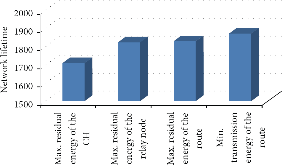
Comparison of network lifetimes of four criteria for the fitness function.
6.2.2. Maximizing Residual Energy of the Relay Node
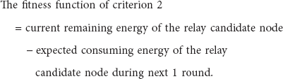
Since the role of the relay nodes is to assist their CHs not overstrained, this criterion aims to relieve the workload of the relay node. The transmitting CH calculates the values of the fitness function of all routes as follows.
6.2.3. Maximizing Residual Energy of the Route
From the point of view of load balance or entire energy consumption, the energy of CH and the energy of a relay node are considered to be better together. The transmitting CH calculates the values of the fitness function of all routes as follows.
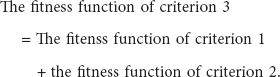
Criterion 3 considers the energy of the CH and the energy of the relay node together. In Figure 4, the lifetime of criterion 3 is higher than that of criterion 1 and that of criterion 2. This implies that criterion 3 maintains a load balance better than criterion 1 and criterion 2. However, the comparisons of direct transmission and using transmission via a relay node are not exact. Since a direct transmission consumes the CH's energy only, the average residual energy of the CH at direct transmission can be about half of that of transmission via a relay node.
6.2.4. Minimizing Transmission Energy of the Route
To resolve the problem of the fitness function of criterion 3, this criterion considers consumed energy of the CH and the relay node rather than the residual energy. The transmitting CH calculates the values of the fitness function of all routes as follows.

6.3. The Validity of Using Relay Nodes
To prove the validity of the cooperative communication method, we compare between the network lifetimes of EECC (using relay nodes) and that of SOSAC (without relay nodes).
Figure 5 demonstrates that the network lifetime of EECC is between 20.7% (when the 1st sensor node is drained) and 9.7% (when the 20th sensor node is drained) longer, compared to the network lifetime of SOSAC. This experiment indicates that the cooperation of CHs and relay nodes prolongs the network lifetime by reducing energy consumption and maintaining load balance.

Comparison of network lifetimes of EECC and SOSAC.
6.4. Comparisons of Basic Performance with HEED
In this section, we compare the network lifetimes and residual energies of the sensor nodes of EECC and the hybrid-energy-efficient distributed clustering approach (HEED) [18], which is a well-known cluster-based intercluster routing protocol. The HEED forms clusters and establishes intercluster routes in order to raise energy efficiency. To decide the appropriate CHs, HEED utilizes two parameters. The first parameter is residual energy of sensor nodes. The second parameter is the (i) minimum degree cost, (ii) maximum degree cost, and (iii) average minimum reachability power (AMRP) to solve break-ties. To establish proper intercluster routes, HEED uses the breadth-first search tree (BFST).
First, we compare the network lifetimes of EECC and HEED. Figure 6 shows that the network lifetime of EECC is 101.3% (when the 1st sensor node is drained) longer and 6.3% (when the 20th sensor node is drained) longer than the lifetime of HEED, respectively. This implies that using relay nodes through the cooperation of CH and their relay node is a suitable application. EECC controls CHs so as not to consume energy quickly by spreading transmission energy of CHs based on the appropriate relay selection, which allows a relatively long network lifetime.

Comparison of network lifetimes of EECC and HEED.
Second, we compare the average ratios of the residual energies of EECC and HEED. In Figure 7, the average ratio of residual energy of EECC is between 57.4% (when the 1st sensor node is drained) and 43.4% (when the 20th sensor node is drained) smaller than that of HEED. This implies that the energy consumption of the entire sensor nodes of EECC is more balanced than that of HEED.
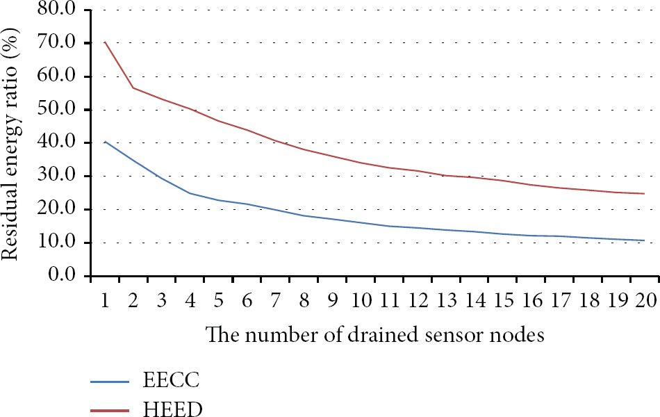
Experiment on the residual energy ratios of EECC and HEED.
6.5. Scalability of EECC
In this section, we experiment the scalability of EECC. Since the sensor fields of WSNs can vary according to the locations, the scalability of clustering and routing protocols is needed. In this experiment, the sizes of sensor field are increased from 200 m * 200 m to 300 m * 300 m and the number of sensor nodes is increased from 100 sensor nodes to 200 sensor nodes, in order to prove the scalability of EECC.
Figure 8 shows the network lifetime of EECC when the sizes of the sensor field and the number of sensor nodes are increased. When the size of sensor field is fixed, according to the increase of the number of sensor nodes, EECC tends to increase the network lifetime. In contrast, when the number of sensor nodes is fixed, according to the increase of the sizes of sensor field, EECC tends to slightly decrease the network lifetime. The reason is that transmission ranges of sensor nodes are increased, since the density of sensor nodes is decreased. Therefore, we can conclude that EECC has reasonable scalability.
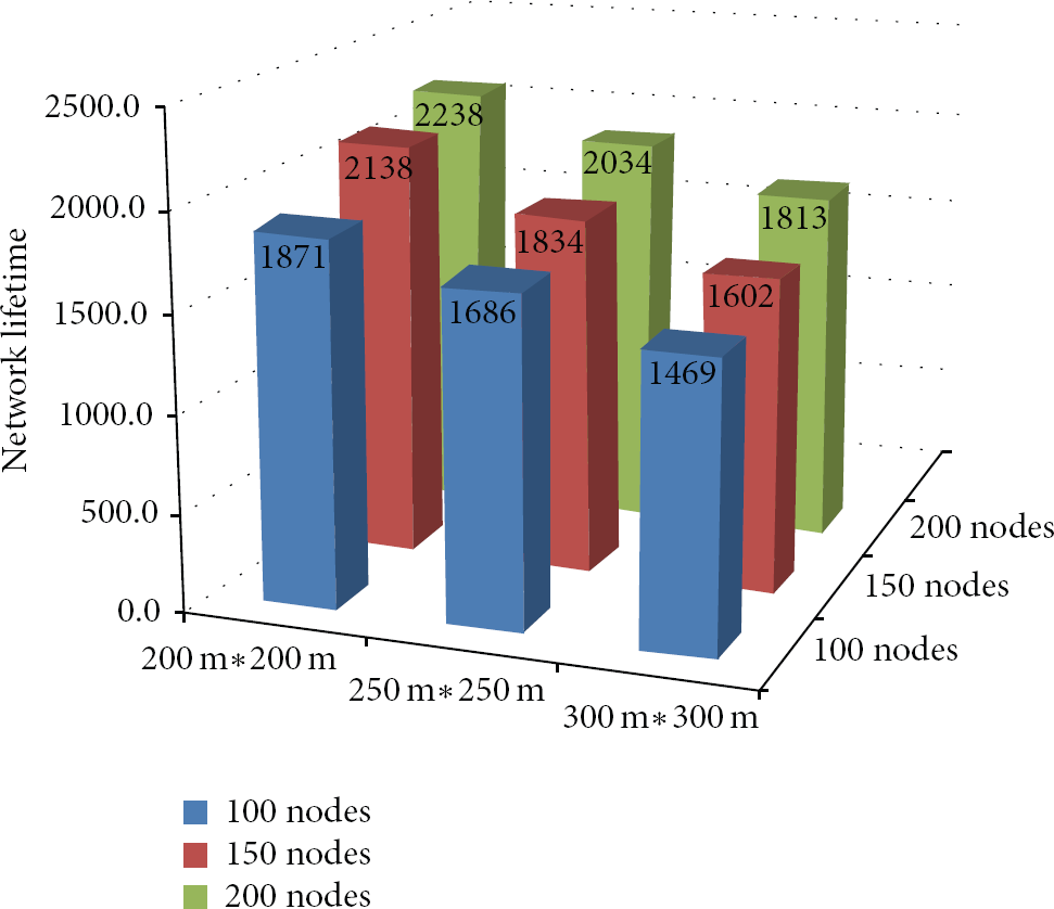
Experiment on the scalability of EECC.
7. Conclusion
This paper proposed an energy-efficient cooperative communication model with clustering and routing schemes for WSNs, the so-called EECC. Since the proposed model utilizes a self-organizing approach, it has good characteristics, such as distributed control, adaptability, and scalability. The proposed model attempts to maximize the network lifetime and to maintain load balance through clustering and intercluster routing by using relay nodes. The key advantage of this model is the appropriate selection of relay nodes that can assist their CH. According to the conditions of intercluster routes, the CHs decide whether or not to use a relay node. It can reduce the transmission range of CHs and also save energy consumption of CHs. As a result, energy states of the entire sensor nodes are more balanced, prolonging the network lifetime of the WSN. The proposed method also demonstrated superior performance compared to that of an existing clustering and routing method.
The relay selection schemes have many interesting research issues. An appropriate research example is the mobile environment. In addition, when the intercluster routing phase is progressed, if relay nodes can be determined, the intercluster relay selection phase can be integrated. It can simplify procedures and reduce overhead cost regarding the establishment of the intercluster routes. As a result, it can become a more energy-efficient and easier method.
Footnotes
Conflict of Interests
The authors declare that there is no conflict of interests regarding the publication of this paper.
Acknowledgment
This work was supported by Mid-career Researcher Program (2013015884) through NRF grant funded by the MEST.