
Abstract
We propose a novel overlay multicast protocol over wireless sensor network, CLOM (cluster and location based overlay multicast) which use both cluster based approach and location based approach. A cluster based approach is used to manage multicast group consisting of relatively large number of nodes while a location based approach is used to construct a multicast tree with rapidity and low control overhead by using geometric information taken from GPS device. Additionally, the information of damping area and the scheme for reducing the CH node discovery time and control overhead have been introduced into CLOM to improve the performance of the tree. The simulation results showed that CLOM works properly with low data distribution delay and low control overhead where the number of multicast group members is relatively high.
1. Introduction
Recently, the need of applications supporting group communication has been gradually increasing both in wired and wireless network environments. The IP multicast has been regarded as the best solution for group communication applications in wired network, but the deployment of IP multicast was delayed for several reasons, such as the cost required for exchanging network equipment, the difficulties of network management, and the security problems. In order to overcome aforementioned disadvantages of IP multicast, the overlay multicast protocols [1–5] have emerged as an alternative to the IP multicast.
However, the introduction of the commercial IPTV and its related services makes it inevitable to deploy the IP multicast. Moreover, initiation of IPTV services leads to the acceleration of wireless IPTV services to offer ubiquitous, incessant, and seamless services to the users. The wireless IPTV services could be applied to various mobile communication infrastructures such as CDMA networks, LTE (Long Term Evolution), Wibro, and MANET (Mobile Ad Hoc Network). Particularly, MANET would play an important role in wireless IPTV in its early stage because it does not require any fixed infrastructure. MANET, an autonomous network, consists of nodes which have dynamic, random, and nomadic characteristics and could connect them. Thus, each node could be regarded as a router as well as an end host in MANET environment. In terms of routing functions, each node maintains routing tables and cooperates to support multihop path connections between two nodes [6, 7]. However, it has some restrictions including lack of bandwidth, limitation of data transmission distance, and channel intervention in data transmission compared to conventional wired-line network, which make it difficult to design, implement, and deploy the wireless network routing protocols in real world. Multicast over MANET also has experienced difficulties in its design and implementation because of the limitations of MANET. In its early stage, a variety of multicast protocols designed for wire-line network were introduced to support multicast functions in MANET, but they could not be applied directly to MANET. Many multicast protocols have been proposed for MANET later on.
To apply overlay multicast in designing and implementing multicast over MANET is also used as an alternative approach as in the wire-line network. As previously described, overlay multicast is originally designed for wire-line network to emulate multicast functions without the help of network equipment. In MANET, it has some advantages in the amount of control overheads and the tree robustness [8–10].
Overlay multicast can reduce the amount of control overheads by tracking group dynamic only rather than underlying topology changes. In other word, the control information used for maintaining the virtual topology is generated only when the virtual topology is changed in overlay multicast scheme. From the viewpoint of the robustness, overlay multicast would maintain virtual topology if nodes included in a group know their neighboring nodes.
2. Proposed Scheme: Cluster and Location Based Overlay Multicast over Mobile Ad Hoc and Sensor Network
2.1. Overview
Most multicast protocols for MANET environment have focused on relatively small group. However, the development of communication technologies, the evolution of applications supporting group communication, and especially the advent of ubiquitous age increase the introduction of MANET multicast protocol which can support relatively large-scale multicast group. In order to construct multicast tree for multicast group having relatively large number of nodes with less control overheads, we use cluster based approach and location based approach requiring GPS devices at the same time. Generally, cluster based approach is fit for large-scale multicast group since it can reduce control overheads by limiting control message's distribution domain within a cluster. In addition, it can also decrease the time complexity of constructing virtual mesh and converting virtual mesh into its corresponding multicast data delivery tree. However, it requires an extra scheme that elects the representative of each cluster, CH (Cluster Head) node, and it needs special cares to deal with CH nodes because the failure or leave of CH node affects the data delivery tree performance adversely. In the worst case, the absence of CH node can cause the collapse of data delivery tree and data transmission can be blocked for a while [11].
In our proposal, CLOM, the location of cluster, and its area are determined by its physical location beforehand. We assume that each mobile node has a GPS device to identify its current location and the cluster which it belongs to. Under aforementioned conditions, we design a CLOM with two layered networks: the intra cluster network and the intercluster network.
The intracluster network, the lower layer network, consists of mobile nodes located in the same cluster. The group member nodes within a cluster build up virtual mesh and elect the CH node according to CH node election scheme by exchanging intracluster control messages. The intracluster control messages are also used to maintain virtual mesh for each cluster by exchanging network status information including the neighboring information of group members, the intracluster topology information, and the intercluster topology information. Note that the intercluster topology information describing topology of CH nodes is also included in its contents and distributed in intracontrol messages to minimize data service suspension duration by seamless switch of CH node. Then, the elected CH node converts virtual mesh into a data delivery tree rooted at CH node using a SPT (Shortest Path Tree) algorithm [12].
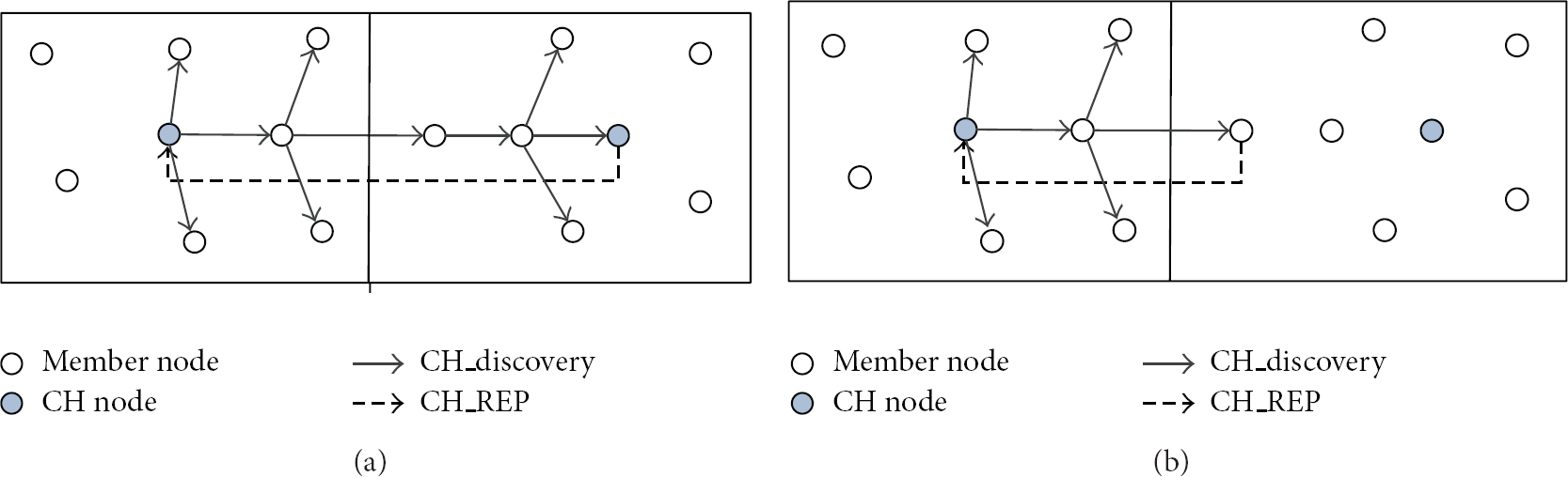
The intercluster network, the higher layer network, consists of CH nodes. In order to create virtual mesh between CH nodes, all CH nodes get their own neighboring CH node information and they construct and maintain virtual mesh based on collected information using intercluster control messages. Next, the root node, the CH node of the source node, forms a data delivery tree for CH nodes from a virtual mesh using a SPT algorithm. Figure 1(a) shows the examples of physical topology and Figure 1(b) shows its corresponding conceptual network constructed by CLOM.

Example of physical topology and the conceptual network.
In order to achieve stable and efficient data service, the data distribution from the source node to whole group members is conducted by following ways considering hierarchical structure of CLOM. First, the source node transmits data to the root node. The root node is the CH node of the source node. It creates intercluster network rooted at itself upon receiving the data from the source node based on its topology table and CH node neighbor table which will be described in the next part. Next, the root node relays data received from the source node to all CH nodes over an intercluster network. Finally, each CH node distributes data received from the root node to its cluster members.
2.2. Protocol Description
In CLOM, there are 9 types of control messages which can be categorized into the intracluster control message and the intercluster control message. Besides, there are three tables—neighbor table, CH node neighbor table, and topology table—to make up and to maintain virtual mesh by cooperation with control messages.
The neighbor table is stored and kept by all multicast group members to maintain and monitor the status of neighboring nodes. In order to construct multicast tree which generates low control traffic and adapts to node's mobility, it has to be maintained in an efficient way. The contents of the neighbor table would be changed by the JOIN_REQ, JOIN_REP, and Hello message. In particular, the neighbor table is mainly affected by the Hello message. The main purpose of the Hello message is to poll the neighbor nodes and to distribute topology information. For example, if one node does not receive the Hello message from its neighbor nodes within the predefined time, it would regard the counterpart node as a failed node. The JOIN_REQ and JOIN_REP messages only change the neighbor table when a certain node joins the multicast group.
The CH node neighbor table is kept by CH nodes to maintain and monitor intercluster network. The CH_Hello, CH_Discovery, and CH_REP messages affect the changes of CH node neighbor table. Among them, CH_Hello message is the most closely related to the CH node table since CH_Hello message is exchanged periodically with node's neighbor CH nodes. The function of CH_Hello message is similar to Hello message except for the boundary and destinations. The Hello message is distributed within the same cluster and its destination is confined to its neighbor nodes located in same cluster area. However, the CH_Hello message has no restriction in its distribution domain and its destinations are the CH nodes placed in other cluster area. The function of CH_Discovery and CH_REP message is also similar to JOIN_REQ and JOIN_REP message, respectively.
The topology table is stored and maintained by all multicast group members. In CLOM, it consists of whole cluster member information included in the same cluster area, CH node information, and the whole intercluster network information.
Particularly, the intercluster information is useful to offer seamless and swift switch of the CH node occurred by the unintentional leave or the failure of the CH node. If the intercluster information is not included in topology table, the CLOM cannot support continuous service because the newly elected CH node should perform CH node discovery procedure to find its neighbor CH nodes. During the CH node discovery procedure, the service offered by CLOM is inevitably suspended since there is no way to receive the downstream data distributed from the source node.
In order to achieve its own operations, each control message should interact with three tables mentioned above. In other words, the insertion, modification, and update operations of the tables are implemented using control messages exchanged among multicast group members. Followings are the detailed descriptions of each control message.
The JOIN_REQ message is generated by the node that wants to join multicast group and it is distributed to intracluster network. Thus it is included in the intracluster control message and only distributed within the same cluster area to which the originator belongs.
The JOIN_REP message is sent by the node which received JOIN_REQ message as a response. The node received JOIN_REQ first stores the information about the node (IP address, hop count, and so on) sent JOIN_REQ into its neighbor table and topology table. Next, it informs the node which sent JOIN_REQ message that group join process was completed by sending JOIN_REP message. In addition, the topology table is also transmitted to the node which sent the JOIN_REQ message to reduce the time required to receive data service from the source node. The node received JOIN_REP message creates its neighbor table and topology table based on the received JOIN_REP message and topology table.
The Hello message is generated by whole group members. The main purposes of the Hello messages are to poll whether neighbor nodes are failed or not by exchanging it between neighbor nodes periodically and to distribute topology information if there is any discrepancy between topology tables of neighboring nodes. To this end, the Fisheye State routing is used in CLOM.
The Leave message is generated by the node which want to leave from a multicast group voluntarily or the node which leaves from the cluster area because of its mobility. The node that received Leave message from its neighbor node deletes the information about the node that sent Leave messages from its topology table and neighbor table.
The CH_ANN message is generated by the CH node of each cluster to inform its cluster members located within the same cluster area of CH node's existence and CH node's information when a new CH node is elected or new cluster is formed. In CLOM, it is broadcast every one second.
The CH_Leave message is generated by the CH node or CH node's neighbor node which found the failure of the CH node to inform its cluster members located within the same cluster area of the CH node's leave or failure. If the CH node moves to other cluster area from the current cluster, it broadcasts CH_Leave message to all cluster members before it escapes from the current cluster area. If the neighbor node of the CH node catches the failure of the CH node, it also broadcasts CH_Leave message to all cluster members instead of CH node. Upon receiving CH_Leave message, all cluster members will attend the CH node election process and pick up the most appropriate CH node using a CH score.
The CH_Discovery message is generated by the newly elected CH node to find neighbor CH nodes. The operation of CH_Discovery is similar to that of JOIN_REQ message except for the distribution range difference between them.
The CH_REP message is sent by nodes which are included in different cluster area and received the CH_Discovery message. Any node received CH_Discovery message sent from other CH node responds with CH_REP messages. Since each node maintains the up-to-date information regarding its CH node by exchanging control messages (Hello message, JOIN_REP message, and CH_ANN), it is useless to relay the CH_Discovery message to the CH node. By operating this way, CLOM can reduce the time required for finding neighbor CH nodes and the amount of control messages generated while the messages is disseminated to the CH node. In addition, the CH node neighbor table will be attached to CH_REP message to inform the newly elected CH node of the information about the whole CH nodes placed in intercluster network. Figure 2 shows how can CLOM reduce the required time and the amount of control messages at the same time.
The examples of reducing the CH node discovery time and control messages.
As shown in Figure 2(b), if the intermediate node which knows the information about its CH node responds with CH_REP against the CH_Discovery message, it can reduce the neighbor CH node discovery time. In addition, the generation of useless control messages indicated as dotted lines in Figure 2(a) can be removed.
The CH_Hello is generated by each CH node periodically. The operation of CH_Hello message is similar to that of Hello message except for the distribution domain and destination. The main purposes of CH_Hello message are to check whether the neighbor CH node is failed or not and if there are some changes in network topology; CH node which finds the modification of topology table notifies the fact to its neighbor CH nodes.
2.3. The Construction of Intracluster Network
2.3.1. Node Join, Leave, Management, and Data Delivery Tree Construction
In CLOM, there are two scenarios in join process which depends on the existence of the CH node. The one is that there is a CH node in the cluster area when a new node wants to join a multicast group. The other is that there is no CH node in the cluster area when a new node wants to join a multicast group.
If there is a CH node in the cluster where a new node wants to join a multicast group, node's group join process is done by following steps
Node I starts neighboring discovery process using an ERP (Expanded Ring Search) technique by distributing JOIN_REQ message to group members placed within the same cluster area. Under this environment, the hop count is set to 1 for the first time and then the value is increased by 1. When node J receives JOIN_REQ messages from node I, it records node I as its neighbor node in the virtual mesh, along with the hop distance. It is done by inserting the node I's information into node J's neighbor table and topology table. Node J sends back JOIN_REP message to node I with topology table, so that node I understands the whole network information. The information of node J is inserted into node I's neighbor table and topology table.
Node I's join process will be completed upon receiving JOIN_REP message from Node J. Then, node I participates in multicast group and starts operations as a group member.
If node I cannot receive JOIN_REP message within the predefined time period for three times consecutively, node I regards itself as a CH node of the cluster and node I broadcasts CH_ANN message to inform its cluster members of its existence and information such as IP address and hop distance. And then, Node I starts neighbor CH node discovery process by distributing CH_Discovery message.
In CLOM, the leave process of normal member is simple. The node that wants to leave multicast group sends Leave message to its neighbor nodes. Upon receiving Leave message, neighbor nodes remove information of the leaving node in their neighbor table and topology table. The abrupt leave or failure of the neighbor node could be seen by the Hello messages. In order to maintain up-to-date neighbor and topology tables, each group member exchanges hello message to its neighbor nodes periodically. If a node finds some changes in network status, it will inform its neighbor nodes of the network status modifications using Hello message to which the discrepancy of network status information is appended.
However, the leave process of CH node is somewhat complicated and special cares have to be paid. There are two possible scenarios of CH node's leave: a voluntary leave and an unintentional leave. In a voluntary leave, CH node broadcasts CH_Leave message to group members located in the same cluster area. Upon receiving CH_Leave message, members within the same cluster area elect a new CH node according to CH node election process which will be described later more precisely. In an unintentional leave, the fact of the CH node's absence or failure will be found by CH node's neighbor nodes when they exchange Hello messages. In this case, the node finding the leave of the CH node broadcasts CH_Leave messages to inform group members within the same cluster.
In addition, the CH node periodically distribute topology table including the status of cluster member nodes and all CH nodes. Using the aforementioned topology table distribution and Hello message exchange, each node can maintain the newest network information.
In CLOM, the data delivery tree is calculated based on virtual mesh using a SPT (Shortest Path Tree) algorithm rooted at the CH node. It is reconstructed whenever the status of intracluster network is changed.
2.3.2. CH Node Election Process
The CH election process will be performed when existing CH node leaves the multicast group or a new cluster is built up. The CH node candidates include all group members positioned within the same cluster area. In the CH node election process, the most important factor is how long the elected CH node will stay in the cluster area since frequent replacement or failure of CH node can affect the performance of multicast network in an unfavorable way. Thus, the node that has the least possibility of leaving the cluster area should be picked up as a CH node. For this end, the CH score function is introduced, the value of which is determined by combination of Dist function and Speed function of mobile 11 nodes.
In order to define CH score function, first the normalization of Dist function and Speed function is required. Equations (1) and (2) represent the Dist function and Speed function, respectively:
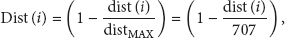

As shown in (1) and (2), the value of Dist function is determined by the physical distance from the center of the cluster area to the mobile node and the value of the speed function reflects the moving speed of the mobile node. The location and speed information of each mobile node can be easily gathered by using GPS device since all nodes are equipped with GPS device.
The calculation of the CH value is shown in the following based on (1) and (2):

Through simulation, we will select the most appropriate Alpha value, which minimizes the changes of the CH node.
2.3.3. The Handover Management
In MANET environment, every node is apt to move in the random and unpredictable way. In CLOM, nodes moving from one cluster to another have to be dealt carefully. Node's frequent cluster changes can degrade the tree's performance because they require the rebuild or change of intracluster network related to moving node.
Figure 3 shows the examples of node's movements that affect the performance of tree significantly. Case 1 shows that a node moves from cluster A to cluster C with a zigzag way. Under this circumstance, intracluster networks for cluster A and cluster C will be updated frequently according to node's move and it will increase the dynamic of intracluster network. Case 2 shows different pattern of node's movement. In this case, clusters A, B, C, and D are affected by node's migration and their intracluster networks are also oscillated. In case 3, clusters C, D, and B are affected by node's shifting. There would be other patterns that influence the intracluster network, but we show three types of movement patterns of nodes here to stress the need of node's handover management.

Example of node's movement.
In order to damp the network dynamic caused by node's moving pattern, we introduce the damping area within a cluster area. Using the damping area, nodes moving from one cluster to another suspend their cluster changes until they get out of damping area.
Figure 4 illustrates the cases that node's frequent cluster changes are restricted by the damping area. In case 1, the moving node does not change its cluster and does not affect cluster B since its moving trajectory is limited within a damping area. Compared with case 1 of Figure 3, the number of moving node's cluster changes is sharply dropped and it can result in the stability of the intracluster network for cluster A and C at the same time. In case 2, the moving node does not affect intracluster network for clusters A, B, C, and D. In case 3, the moving node affects the intracluster network for clusters C and B. Compared with case 3 of Figure 3 where node's movements influence intracluster networks for clusters C, D, and B, it can also increase the stability of cluster network.

Example of restricting the frequent cluster changes of nodes using a damping area.
In addition, damping area is also applied to the CH node for seamless switch of the CH node. If the CH node moves into damping area, it would broadcast CH_Leave message to its cluster members.
2.4. The Construction of Intercluster Network
The process of constructing a virtual mesh for intercluster network is similar to that of intracluster network. In CLOM, the CH_Discovery message is used to detect the neighbor CH nodes. In this case, the ERP technique is also used but the initial hop distance is set to 3 and the value of the hop distance will be increased by 3 in every attempt. Upon receiving the CH_Discovery message, the CH node or normal node which received it responds with the CH_REP message including whole inter cluster network information that is appended in the form of table. The CH_Discovery message is used only when the newly elected CH node does not know the intercluster network information. However, it is very rare to generate the CH_Discovery message since most member nodes grasp the intercluster network information by exchanging topology table. In order to maintain intercluster virtual mesh, the CH_Hello message is exchanged between neighboring CH nodes periodically. If some changes of intercluster network information are detected, the change information would be distributed by the CH_Hello message, so that all CH nodes maintain up-to-date network information.
The data delivery tree of intercluster network can be computed based on current virtual mesh of intercluster network by using a SPT algorithm rooted at the root node having the source node as its cluster member node.
3. Performance Evaluation Using Simulations
3.1. Simulation Environment
In order to evaluate the performance of CLOM, the simulations are implemented using the NS-3 network simulation tool. In this model, 200 mobile nodes are placed in a 2000 m by 2000 m area. The whole area consists of 4 cluster areas each of which occupies 1000 m by 1000 m area. The movement of mobile nodes is determined by “setdest” software embedded in NS simulator. The functions of the setdest are as follows. First, it determines the random location of each mobile node. Then it sets the destination of mobile nodes to be reached and it automatically reallocates new destination of mobile nodes if they reach their destinations. For performance comparison, semi-Multicast protocol is used which is similar to CLOM except that it does not support cluster-based approach. The detailed parameters of the simulation are shown in Table 1.
The detailed parameter of simulation.

3.2. The Selection of Alpha Value
CH value is determined by the combination of Dist function, speed function, and Alpha value. Among them, the output values of the Dist function and speed function cannot be changed because they are automatically determined by mobile nodes’ distance from the center of the cluster to their current location and their moving speed. However, the Alpha value can be treated as a variable. Thus, we can get the most suitable multicast tree by manipulating the Alpha value in simulation as a parameter.
As mentioned earlier, frequent changes of the CH nodes affect the tree performance adversely. That is because the changes of the CH node can bring about the collapse of the cluster to which it belongs for a while. Therefore, special attention has to be paid in selecting Alpha value, which can minimize the changes of the CH nodes. In order to take the most appropriate Alpha value, we conduct simulation by varying the Alpha value from 0 to 1.0 for 1800 simulation seconds.
Figure 5 shows the number of CH node changes according to the speed of mobile nodes when 80 mobile nodes were joined in the group and moved in a random way.

The number of CH nodes’ changes.
According to the simulation results, the number of the CH nodes’ changes reaches its maximum value where the Alpha value is 0.0. However, the number of CH nodes’ changes is approximate in most cases (from 0.1 to 1.0). Note that the CH value of each mobile node is determined by only speed function where the Alpha value is 0. It means that the mobile node having the lowest moving speed within the same cluster is elected as a CH node regardless of its location. Under aforementioned circumstance, it is likely to easily depart the cluster area if the newly chosen CH node is placed near the border of the cluster area.
Figure 6 shows the snapshot for the number of the CH nodes changes where the node's maximum moving speed is 10. As shown in Figure 6, the number of the CH nodes changes is distributed 0 to 5 where the Alpha value is not a 0.2, but the number of CH nodes’ changes is distributed more widely and randomly where the Alpha value is a 0.0.

The Snapshot of the number of the CH nodes’ changes where the node's MAX Speed is 10.
The number of CH nodes changes reaches its minimum value where the Alpha value is 0.2. It means that the multicast tree will show best performance when more weight (0.8) is given to speed in calculating the CH value. However, the number of the CH nodes change is relatively small and the difference among the cases is slight. For more detailed analysis, we introduce the average number of CH node's changes as shown in Figure 7 because it is difficult for deciphering Figure 5.

The average number of CH nodes’ changes.
As shown in Figure 7, the average values of CH nodes’ changes is less than 2 in most simulation runs except the case where Alpha value is 0.0. That is because the cluster area is well chosen for mobile nodes moving with low speed. However, the situation will be changed if the movement speed of mobile nodes increases.
3.3. The Average Delay
In the application software using data distribution, the average delay could be regarded as the most important criterion to determine the feasibility of the application. That is because the high average delay makes it difficult to deploy in the real world. In order to investigate how the Alpha value influences the average delay, we conduct simulations with the Alpha value of 0.0 which stands for the worst case and the Alpha value of 0.2 representing the best case. In addition, we include the semi-Multicast for performance comparison.
Figure 8 shows the average delay of each condition according to the maximum moving speed of mobile nodes. As expected, CLOM shows its best performance where Alpha value is 0.2. The performance difference between where Alpha value is 0.2 and where Alpha value is 0.0 is about 29% and the difference between Alpha = 0.0 and the semimulticast is around 57%. In most cases, the average delay increases as the speed of mobile nodes increases. Note that the average delay of Alpha = 0.0 reaches its peak value where the maximum node speed is 5 m/Sec. That is the example of the frequent changes of the CH nodes can block the operation of the protocol for a while.

The average delay.
3.4. The Maximum Delay
The maximum delay also could be regarded as a criterion to determine the feasibility of MANET protocol. In reality, it is not easy to lower the maximum delay over MANET environment because of the characteristics of MANET. In this section, we measure the maximum delay of the CLOM and semi-Multicast and analyze the feasibility and the performance of them based on measured results.
Figure 9 shows the maximum delay of the proposed protocol (Alpha = 0.0, Alpha = 0.2) and semi-Multicast. In most conditions, the semi-Multicast shows the low maximum delay than proposed protocol both Alpha = 0.0 and Alpha = 0.2. That is because the difference of data distribution method between the proposed protocol and semi-Multicast. Under the normal state, both CLOM and semi-Multicast operate based on their own protocol operations. However, they will perform failure recovery process under the abnormal state and there are some differences in their data distribution scheme after the failure recovery process.
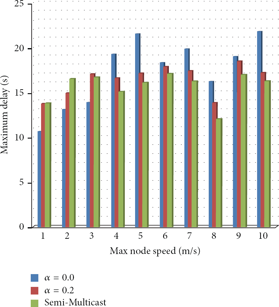
The Maximum delay.
Figure 10 shows why CLOM has the relatively long maximum delay compared with semi-Multicast. In semi-Multicast, data sent by source node can be delivered to destination node just via node 4. However, data has to go through nodes 5, 6, CH node, 9, and then destination. In other words, CLOM has longer data distribution delay time in its initial phase. In addition, the failure or change of the CH node of the CLOM can delay the maximum delay time.
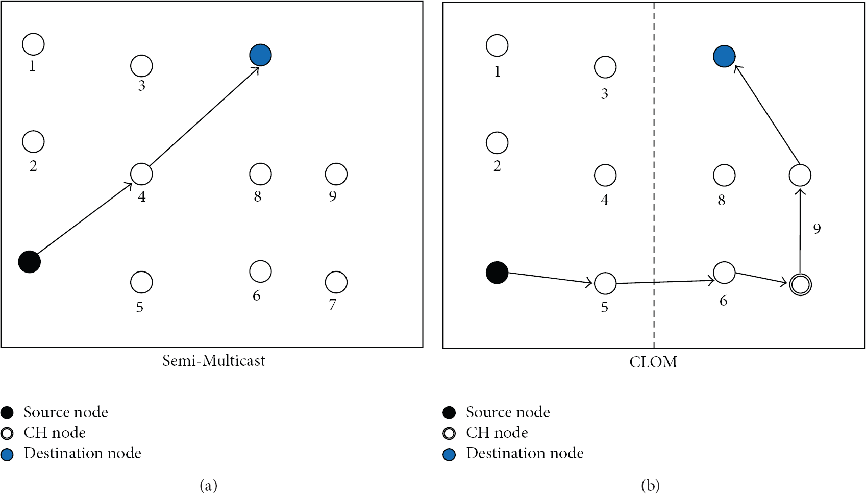
The examples of data delivery scheme in Semi-Multicast and CLOM.
For most cases, the maximum delay occurred from CLOM and semi-Multicast reaches or goes beyond 15 Sec. However, it occurs under unusual conditions such as a temporary failure of wireless link, a temporary wireless link interference, and so on. In other words, the data transmission of some nodes is temporarily stopped because of the characteristics of MANET and results in an exceptionally long suspension of service.
3.5. The Control Traffic Ratios
The control traffic ratio has been the continuous interest in network protocol design. Particularly, the decrease of the control traffic is more important in wireless network than its counterpart wired network because of its characteristics such as a limited bandwidth, instability of the connection that comes from its mobility, and channel interruption of MAC layer.
In this section, we calculate the control traffic ratio based on measured results and analyze them. Figure 11 shows the control traffic ratio of CLOM and semi-Multicast according to nodes’ maximum moving speed.

The control traffic ratios.
According to Figure 11, the control traffic ratio has gradually increased as the node's moving speed increases except where the node's maximum speed is 6 m/Sec. The CLOM generates less control traffic than the semi-Multicast on average. That is because the broadcasting domain of control traffic in CLOM is limited within each cluster except for intercluster messages. In case of semi-Multicast, there is no scheme to prevent control traffic from spreading whole area. In addition, the control traffic ratio is relatively low because we use relatively high-capacity data source.
In terms of the amount of control traffic, the CLOM with Alpha = 0.0 reduces the control traffic generation by 4% only and the CLOM with Alpha = 0.2 reduces it by 11%. In addition, CLOM generates more control traffic than semi-Multicast where the node's maximum speed is 1 m/Sec, 2 m/Sec, and 3 m/Sec. That is because the need for multicast tree reconstruction come from nodes’ mobility is few under the situation where each mobile node moves with low speed. Few topology modifications make the semi-multicast to generate less control traffic. The CLOM, however, needs to generate intercluster messages regardless of node's movement speed.
3.6. The Connection Ratios
In order to serve data distribution over MANET environment, the connection ratio of group members is a critical factor. The low connection ratio can bring about the degradation of service quality. Figure 12 shows the connection ratio of the CLOM with Alpha = 0.0, Alpha = 0.2, and semi-Multicast. The connection ratio, on average, reaches 99.6%, 99.725%, and 99.525% in the CLOM with Alpha = 0.0, Alpha = 0.2, and semi-Multicast, respectively. It means that three proposals are suitable for data distribution service.
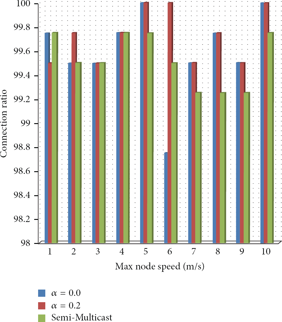
The connection ratios.
4. Conclusion and Future Work
In order to construct overlay multicast tree over MANET, the CLOM exploiting the cluster based approach and the location based approach at the same time is proposed. Generally, the cluster based approach is used to deal with a large group. In CLOM, the cluster based approach is used to prevent the control traffic from being distributed to the whole area rather than a cluster area. The location based approach is used to define each cluster area beforehand and to identify the exact location of each mobile node. In addition, the GPS device required for using the location based approach makes it possible to calculate the CH value which could be taken by the speed of mobile node and the distance from the center of the cluster to the current location of mobile node.
By performance evaluation, the CLOM shows better performance than semi-Multicast in terms of the average delay, the control traffic ratio, and so on.
However, there are some researches that have to be conducted in CLOM. The first one is to find the relationship between the moving speed of the mobile nodes and the suitable size of the cluster area. Under the condition where each mobile node moves with relatively low speed, the suitable size of the cluster area will be decreased. On the other hand, the increase of node's moving speed will make the increase of the size of the cluster area. The second one is to find the way to reduce the number of the CH nodes’ changes by improving the CH value function. As shown in simulations, the frequent changes of the CH node can bring about various side effects such as the increase of the average delay, the increase of the control traffic ratio, and the decrease of the connection ratio.
Footnotes
Conflict of Interests
The authors declare that there is no conflict of interests regarding the publication of this paper.
Acknowledgment
This research was supported by the MKE (The Ministry of Knowledge Economy), Korea, under the ITRC (Information Technology Research Center) support program (NIPA-2013- H0301-13-1006) supervised by the NIPA (National IT Industry Promotion Agency).