
Abstract
Laser texturing is a relatively new multiprocess technique that has been used for machining 3D curved surfaces; it is more flexible and efficient to create decorative texture on 3D curved surfaces of injection molds so as to improve the surface quality and achieve cosmetic surface of molded plastic parts. In this paper, a novel method of laser texturing 3D curved surface based on 3-axis galvanometer scanning unit has been presented to prevent the texturing of injection mold surface from much distortion which is often caused by traditional texturing processes. The novel method has been based on the computer texture mapping technology which has been developed and presented. The developed texture mapping algorithm includes surface triangulation, notations, distortion measurement, control, and numerical method. An interface of computer texture mapping has been built to implement the algorithm of texture mapping approach to controlled distortion rate of 3D texture math model from 2D original texture applied to curvature surface. Through a case study of laser texturing of a high curvature surface of injection mold of a mice top case, it shows that the novel method of laser texturing meets the quality standard of laser texturing of injection mold.
1. Introduction
Laser texturing is a relatively new multiprocess technique that has been used for creating decorative texture on injection molds to improve the surface quality and achieve cosmetic surface of molded plastic parts [1]. The laser processed texture is copied to the molded plastic parts to create a desired visual effect as below [2]:
to give a part the appearance of leather, wood, stipple, sand, or whatever simulated effect;
to give parts an evener, planned effect or to get rid of a glossy appearance, and change to a matte finish. This can add richness to a part's appearance, therefore making the part more marketable and giving it a perception of higher value and quality;
to build a company's logo or a random or geometric pattern into the appearance of the part that immediately identifies the part as belonging to that particular corporation.
There are numerous techniques of texturing such as electrical discharge machining, chemical etching, photochemical etching, and laser texturing. Each of the purposed techniques is to remove materials from the surface of a component to form a texture or a pattern on the surface that will transform the visual appearance of the final product.
Such techniques often cause distortion or warp of texture on 3D surface of mold cavity, especially on high curvature surface, since the texture is often projected on the surface instead of being mapped. In this respect, laser texturing is the best techniques with less distortion because the technology of computer mapping texturing is used, and the process is reproducible, accurate, flexible, and fully automated.
The distortion rate of mold texturing is often required under 3.6%, but current texturing techniques, including laser texturing, could not meet the requirement. This paper is aimed to study an effective computer texture mapping with controlled distortion rate as mentioned above.
Laser texturing is based on computer texture mapping technology. It is impossible to design 3D file that represents textured surface of components in detail due to the thousands of MBs in size [1]. Therefore, texture mapping is needed to generate 3D model of texture, which is transferred from 2D texture in the CAD environment with controlled warp or distortion. A planar projection is easy to create on any object, but it appears correct only from one viewing angle. For example, it is impossible to create a pattern consisting of rectangular on angled surfaces. This distortion can be optimized or minimized by correct texture mapping. Figure 1 shows the mapping process of mold surface from 2D texture to 3D texture model, which is identified and applied by the system of 3-axis galvanometer scanning unit to ablate the texture on the surface of the mold.
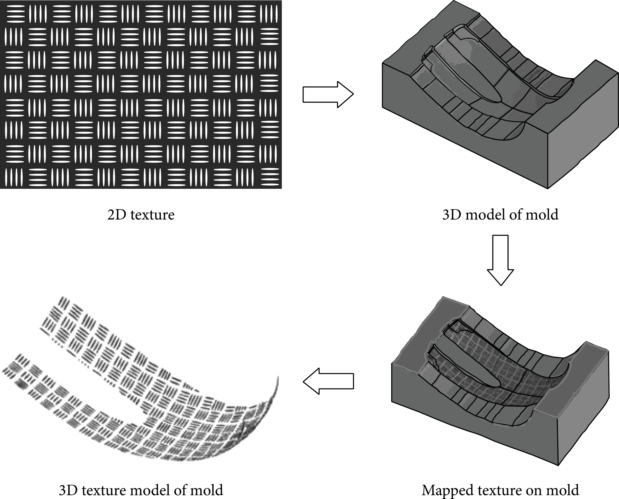
Texture mapping process.
Figure 2 indicates the principle of the system of 3-axis galvanometer scanning unit for laser texturing of a mold.
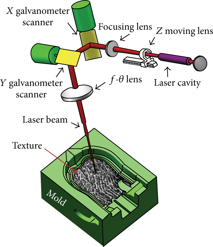
3-axis galvanometer scanning unit.
In the 3-axis scanning unit, the laser beam first enters a Z moving lens and focusing lens. After moving lens, the beam diverges rapidly until it enters one or two focusing lenses. The beam, now converging, passes through and is directed by a set of X and Y mirrors moved by the galvanometer scanners. The orthogonal arrangement of the X and Y mirrors direct the beam down towards and over the length and width of the working field. The focusing height of laser is adjusted by moving Z lens according to the Z coordinates of 3D leather texture model which is the result of computer texture mapping from 2D leather texture.
2. Texture Mapping Algorithm
Texture mapping has been widely studied in traditional computer graphics but rarely studied in the field of laser texturing and marking except in Europe mold industry [3]. Texture mapping for laser texturing is aimed to control and minimize mapping distortion and warp in important area of 3D surface, whereas it cares about the even distribution of distortion in traditional computer graphics [4–6]. As a common practice of mold texturing, texture mapping algorithm should satisfy the following requirements:
single patch free boundary parameterization,
guarantee one-one-mapping,
offset, scale, and orientation control,
nonuniform distortion control,
distortion should take the angle and stretch into account.
2.1. Surface Triangulation
Mold cavity surface model with a certain degree of smoothness has to be triangulated before a decorative texture can be mapped [7, 8]. The triangulation has to be dense enough and preferably fairly regular in shape without sharp angle. The triangulation algorithms in CAD application usually generate triangulation that minimizes the number of generated triangles and vertices. Surface triangulation is usually performed in some artistic modeling software.
2.2. Texture Mapping Algorithm
2.2.1. Notations
Texture mapping is a transformation from object space to texture space; textures coordinates (u,v) are assigned to a vertex (x,y,z).
Given a triangle mesh M = {V, F}, where V = {ν i }, ν i = ∈ R3, and F = {f i } stand for the vertices and faces [9, 10]. The parameterization result, that is, the u-v coordinates of vertex ν i , is represented by ν i = ∈ R2. The weighting of distortion is given on texture space as ω(u).
For a face with vertices u a , u b , and u c , with the help of the normal n, we evaluate a rotation to map them onto x-y plane Ru*, where Rn = (0,0,1) T . Then the face can map to the x-y plane without any distortion by ω* = R(0:1,:)u* ∈ R2; L2(R2). Then for a point p = ∈ R2 in triangle (ω a ,ω b ,ω c ), its parameterization coordinates is

where ϕ(p) is the barycentric coordinates of p in the triangle:

Thus, the parameterization Jacobian on this triangle is

2.2.2. Distortion Measurement
Given the parameterization Jacobian J2×2, the following quadratic energy evaluates the angle (conformal) distortions (LSCM):

where Rπ/2 is the π/2 2D rotation.
The stretch (isometric) distortions can be measured by the nonlinear energy:

where s stands for the desired stretch (default can be 1). Finally, the total energy is

where (f
i
) is the area of the triangle f
i
, and ω* is the weighting for the distortion on the texture space triangle

2.2.3. Control
For better flexibility, we would like to control the result by the following boundary conditions:
position: C p u = u p , where C p is an interpolation matrix and u p is the desired parameterization coordinates. For simplicity, we specify the position constraints at mesh vertices.
scale: ∥J(:,i)∥2 = s2, where s is the desired scale.
orientation: 〈J(:,i),Rπ/2d〉 = 0, where d ∈ R2 is the desired direction for J(:,i).
2.2.4. Numerical Method
When ω s ≠0, it is nonlinear optimization, thus needing a method to evaluate a good initial value. It can be finished by discarding the stretch term first and make the energy into a quadratic one.
For the nonlinear optimization, Gauss-Newton iteration with Trust-Region strategy should work well.
To solve these problems, the following equation will be used:

Boundary condition is required to avoid degeneration. In the initial value step, we fix the parameterization coordinates of an arbitrary vertex p (e.g., the first vertex) into an arbitrary one (e.g., (0, 0)). Then the parameterization coordinates of one of its neighboring vertex q is fixed to (s∥p − q∥,0). After getting the initial value, the parameterization coordinates should be uniformly scaled into αu as the initial value, α is solved from

The second boundary condition should be removed when applying the stretch measurement.
3. Implementation
3.1. Uniform Conformal Mapping
In this case, any similar transformation on parameterization result does not affect the distribution of error; we can apply the control as a simple postprocessing.
3.2. Nonuniform Conformal Mapping
In this case, the control cannot be applied as postprocessing and must be formulated as boundary condition. The challenge is that the weighting is on the texture space. We can use the following iterative method to solve this problem.
At k step, we evaluate the parameterization uk + 1 from the initial value u k :

where ω* k use u k , and E*k + 1 is the function of uk + 1.
4. Interface of Computer Texture Mapping
An interface of computer texture mapping was developed according to above mentioned algorithms. Figure 3 shows that the interactive interface can map several 2D images or textures to injection mold cavity surface of a plastic mice case with minimized distortion which could not be found visually. Figure 4 shows the building process of 3D math model of mapped texture. Figure 4(a) is the model of the mice case, Figure 4(b) is the 2D multitextures which are mapped to the surface of mold cavity, Figure 4(c) shows the mapping result performed by the interface of computer texture mapping, and Figure 4(d) is the final target of 3D math model of mapped texture, which is used for 3-axis galvanometer scanning unit to ablate or texture the surface of mold cavity. The 3D math model of mapped texture could not contain the original 3D surface model of mold cavity any more.
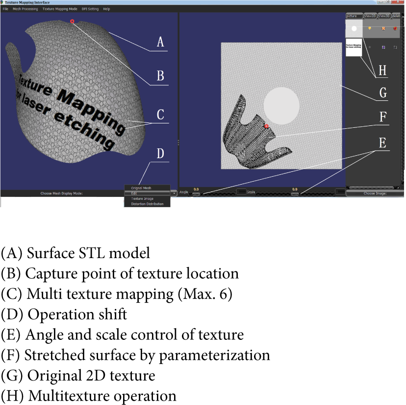
Interactive interface of texture mapping.

Building process of 3D math model of mapped texture.
Figure 5(a) shows a high curvature surface of a mold cavity of a mice key top was laser ablated based on its 3D math model of mapped texture of serious hexagons; the distortion rate of length of each side of all hexagons ablated on the high curvature surface is less than 1.2%, resulted from both measured data of CCD projector and calculation according to surface curvature. Figure 5(b) is the CCD image of measurement; the quality of each side of all hexagons is excellent without any marked burr, and it is impossible to achieve such high quality performance by other texturing techniques, the laser texturing took 10 minutes only to ablate the cavity surface of the mice mold, whereas other texturing processes had to take 2 hours at least.

Laser texturing process of a mold of mice key top.
5. Conclusion
Texture mapping is a well-known technology in the field of traditional computer graphics, but it is quite new in the industries of laser texturing, marking, ablating, and engraving for the decoration of 3D surface of product or mold. Regarding to mapping distortion and warp, traditional texture mapping focuses on the research of control of uniform rate around whole surface, however, the interface of computer texture mapping developed in the paper can sacrifice unimportant area of surface with big rate, in order to ensure low rate in important area instead.
Texture mapping algorithm presented in this paper makes least amount of texture distortion on 3D surfaces; the mapping process in the developed interactive interface is well planned and executed with high effectiveness so that laser texturing is a versatile technique for high quality decoration of 3D surface of products in high efficiency.
Further research will provide the solution of keeping same laser energy during laser texturing process, an X-Y rotation table, which installs injection mold, together with the 3-axis galvanometer scanning unit presented in this paper, will form 5-axis laser machining system so that the laser beam is often orthogonal to the activated surface of injection mold without laser energy loss.
Conflict of Interests
The authors declare that there is no conflict of interests regarding the publication of this paper.
Footnotes
Acknowledgments
This work was supported by Guangdong Natural Science Foundation in China (S2013010015726), Shenzhen Science and Technology Research Foundation in China (ZYA201007070116A), Research Fund between Shenzhen Institute of Information Technology and Hymson Laser Co., Ltd. (A2012H02). The authors are greatly indebted to many field engineers for helping conducting lots of in-situ tests.