
Abstract
The manufacturing of medium-sized hollow parts using a foamed high density polyethylene was studied using a conventional accumulator blow extrusion machine and a systematic capture of pictures during the parison formation. To fully monitor the parison formation, several experiments were carried out varying the chemical foaming agent content from 0 wt.% to 2 wt.% and increasing the push extrusion speed. Results pointed out greater wall thickness, diameter, and length of parisons with higher weight percentage of blowing agent and extrusion speed. A full experimental characterisation of parison dimensions was essential to assure a proper prediction of the blowing step. Information was used as input for modelling and simulations of the blowing phase of an industrial container. To validate the proposed methodology, a blow moulding process of a generic container was simulated using Ansys Polyflow v13 software and its finite element analysis which provided an accurate approximation of the wall thickness expected. Further real tests on the simulated container also demonstrated that, in those parisons with a 1 wt.% CFA concentration and higher blowing pressure, there was remarkable improvement on their packaging properties such as decreasing of the total weight of the container and an enhancement of its surface quality.
1. Introduction
Reduction of weight has been of special interest due to the potential of saving and has been achieved by different strategies including materials and design optimization. The concept has been of special relevance in those sectors directly related to transportation such as aviation and automotive [1–3] and indirectly to those concerning the packaging industry [4, 5]. The common goal is to reduce weight to decrease fuel consumption and related costs as well as increase the passenger/cargo load per itinerary; weight also has a direct impact on dynamics and agility [6–8]. Moreover, looking on the current outlook of environmental preservation, a continuous definition and approval of restrictive regulations or the introduction of CO2 emissions targets have resumed a stronger focus on weight reduction as a lever to obtain products with a less relevant ecological footprint and a minimized fuel consumption [9–12].
First attempts of weight reduction consisted in the design of hollow parts and transition of metal pieces into plastic ones. Also ribbed pats or sandwich structures are used as alternatives. Extrusion blow moulding is a usual technique for producing hollow plastic parts, as, for instance, those related to the automotive industry such as windscreen liquid deposit, child's safety seat, expansion tanks, axle cuff, air duct, filler pipe, and oil reservoir among others. The process consists of blowing pressurized air inside an extruded plastic tube called parison, following an inflation process that forces the polymer against the mould cavity, copying the mould shape and forming the part [13, 14]. Due to the fact that reducing weight is always a target to be improved, wall thickness along the parison length can be customized by controlling the mandrel gap on the extrusion die during its extrusion and before the blowing step.
Previous to the blowing stage, it is necessary to characterise the parison extruded in order to define the process parameters window. Controlling the geometry of the parison in this process is very important indeed, as the final thickness distribution relies on it. This makes it necessary to consider the main processing phenomena of an annular flow [4], such as extrudate swell, in particular for non-Newtonian fluids, which exhibit pseudoplasticity (shear thinning or thickening) and viscoplasticity (existence of a yield stress). Regardless, the parison must have sufficient melt strength to remain self-suspended until the mould closes, clamping it [15]. There have been quite a lot of publications studying the theoretical models and simulating this annular flow process, introducing and varying all polymer properties, but to the best of the author's knowledge only a few studies have been focused to validate the experimental results with the results carried out real on-machine [16–18]. In fact, these scientific articles have not been much focused on the study of the shrinkage effect which is our main target in the characterisation of the parison section.
Further reduction in density can be achieved by adding a chemical blowing or foaming agent (CFA). This additive reacts with heat and during its decomposition generates gas bubbles that get trapped within the melt polymer creating a cellular structure. The formed foam reduces the material dosage and thus the costs of the polymer processed notably [19, 20].
In the present research, we proposed a new fast methodology to analyse the blow extrusion process through the parison formation. This methodology has been validated by the production of containers containing different quantities of CFA to study the effect caused on the parison formation in a conventional extrusion blow moulding process [21]. Foamed cells generate a thicker and longer parison with a larger parison diameter due to the die swell effect. After having studied and controlled the parison formation and characterised its formation process, operational parameters were fixed for the processing of a generic water container to be blown. Foamed containers exhibited a noticeable and expected decrease of its weight due to the foaming process. Also different blowing pressures were tested in order to check their surface quality, roughness, and the accuracy of engraved drawings, which were all achieved at certain values.
2. Materials and Methods
2.1. Materials and Equipment
Commercial high density polyethylene (HDPE) Lupolen 5021 DX distributed by LyondellBasell was used as matrix material. This HDPE is an extrusion blow moulding grade polymer with a melt index of 0.25 g/10 min, a solid density of 0.95 g/cm3, and a melting temperature of 190°C. A CFA masterbatch manufactured by Clariant Masterbatch GmbH & Co. OHG was used, containing Hydrocerol CF 40 E as foaming agent for thermoplastic polymer.
For the whole research study, the characterisation of the parison, and the manufacture of the container, the same extruder was used: Mateu & Solé HC75, with a screw diameter of 75 mm, length-to-diameter ratio of 25: 1, and an accumulator capacity of 4.2 L.
2.2. Preparation of the Samples
For the parison characterisation study, the methodology followed started increasing the amount of CFA from 0 wt.% up to 2 wt.% in steps of 0.5 wt.%, 2 wt.% being the maximum loading of CFA recommended by the supplier.
The extrusion blowing process is not continuous. First, the extruder module fills the accumulator head and when it is full a hydraulic piston forces the plastic melt through the die shaping the parison. The control of the piston push movement velocity and the die gap makes it possible to assure the same amount of extruded material in each blowing cycle. The speed at which the piston pushes the parison, the extrusion speed, was set on three different steps, V1 being 50% of the maximum piston speed, V2 60%, and V3 70%.
For the second study, the characterisation of the container, the amount of CFA was fixed at 1 wt.% and the extrusion speed at V2. The container was first blown using a low pressure of 0.3 MPa and then using a higher pressure of 0.7 MPa.
2.3. Methods
2.3.1. Length and Perimeter Determination of the Parison, Wall Thickness, and Foam Distribution
In order to measure the length of the parison, a white board with a 1 cm × 1 cm grid was mounted behind the die head so the parison remained always at the foreground. A camera was fixed on a tripod in front of the blowing module and it was programmed to take a picture every second so the whole extrusion sequence was recorded for its further analysis. Any variation or effect in length was measured using the grid. As the setup was exactly the same for each recording, the sight deviations due to the angle of the camera remain the same for all cases and they do not affect the comparative study shown here.
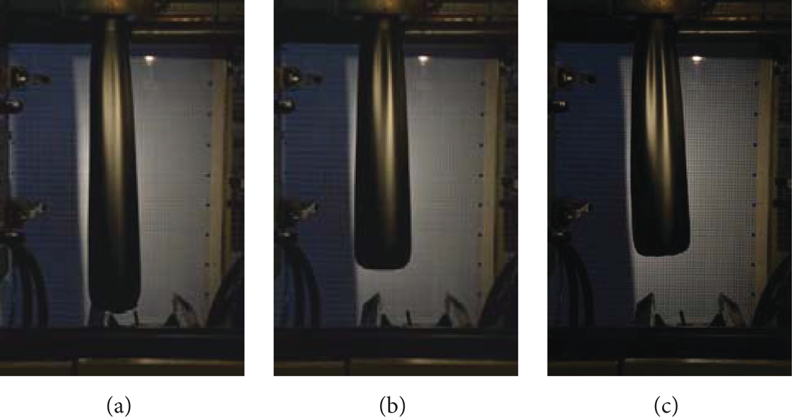
The drawdown or bounce effect which is related to the shrinkage effect of the material, a particular feature that occurs during the parison formation, was specifically analysed. This expected effect takes place when the parison is completely extruded meaning a complete dosage for one cycle extruded from the die. During a few seconds after the extrusion stops, the parison shrinks on its length a distance ΔL until a position where the parison recovers its length again due to its own weight, see Figure 1. Thickness and diameter of the parison were measured directly after quenching it by means of a coolant liquid at room temperature inside a plastic bucket fitted between the open moulds. The final position of the parison at the end of the extrusion was calculated and on that position the end was completely soaked inside the cooling liquid, allowing its hardening and further measuring of thickness and perimeter using a graph ribbon. When cooling down, the parison loses its round shape, so it is difficult to directly measure the diameter. Nevertheless, the change in the perimeter gives an idea of the variation in the diameter [22]. For the thickness measuring, the solidified parisons were introduced into a polystyrene foam box full with liquid nitrogen. Cryogenically frozen parisons were broken in a fragile state making it easier to measure their thickness and observe their internal structure.

Extrusion of a parison: CFA 0% and V1. Total length of the parison (Lend) and the bounce back effect (ΔL) are highlighted on the picture.
2.3.2. The Container
Once the parison was characterised, Ansys Polyflow v13 software [23] was used to simulate the parison blow moulding process of a 10-litre water container, as can be seen in Figure 2. Finite element analysis (FEA) gave an accurate approximation of the dimensions expected in the container under different operating conditions. Figure 3 shows the inflation sequence for the parison moulded into a water container-shaped mould cavity was simulated. The method also lets us to perform and test variations on the blowing process in order to find the optimised parameters and also the optimal parting line of the mould needed prior to the mould manufacturing.

CAD simulated container.

Simulation of the container blowing process with Ansys Polyflow v13. Four steps: (a) clamping, (b) preblowing, (c) closing mould, and (d) blowing.
The simulation process allows us to anticipate a not filled up mould, areas with a very high material extension problems, critical thickness points, and other critical points that might appear during the extrusion trials, being able to anticipate any process and design issues and predict variable wall thickness levels before manufacturing the container [24, 25]. The operation parameters selected for the experimental blowing of the containers were an extrusion speed of 60% (V2) and CFA loading of 0 wt.% and 1 wt.%. How blowing pressure affects the final part quality was also examined being changed from 0.3 MPa for the first case to 0.7 MPa for the second one. The previous experimental trials were also simulated so as to predict blown part dimensions and find further agreements between experimental and simulated results.
3. Parison Results and Discussion
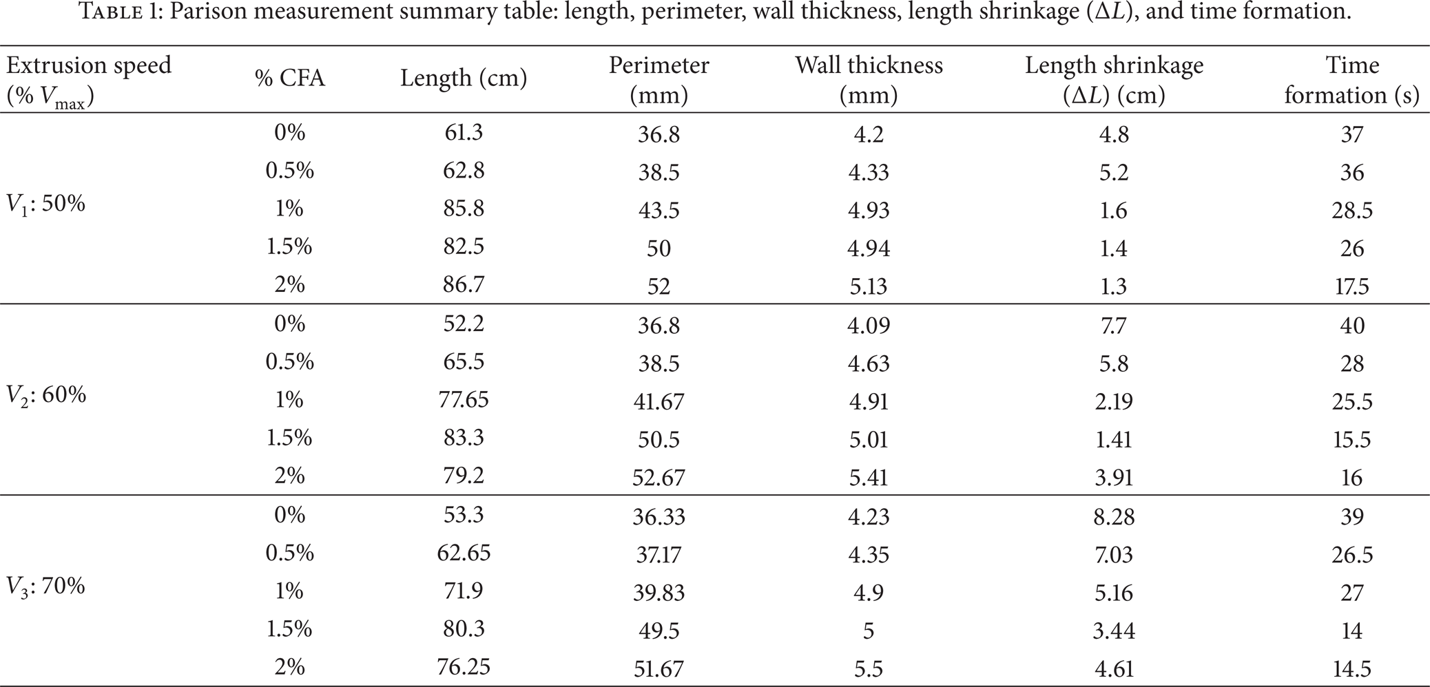
Results measured for all the parison studied cases are summarised in Table 1.
Parison measurement summary table: length, perimeter, wall thickness, length shrinkage (ΔL), and time formation.
Total parison length was captured just before its trimming stage. As it is shown in Figure 4, by increasing the amount of foaming agent the length of the parison increases while by increasing the extrusion speed length slightly decreases. Parison fall results from the equilibrium of gravity and viscous friction forces. Taking into account that foamed polyethylene viscosity is lower than the unfoamed one, the resultant inertial force is much higher leading to longer parison.

Curves represent length against time during the parison formation process. Five lines, one for each chemical agent concentration, are plotted in every graph. Each graph has been obtained at a constant extrusion speed: (a) 50%, (b) 60%, and (c) 70%.
In Figure 4, length versus time is plotted for the five different formulations and for each extrusion speed. In all situations, there is a repeated pattern; first, there is a quick linear relationship before the drawdown appears. The rounded retracted curve shows the length shrinkage of the parison. Then, the length grows slowly again until the parison is heavy enough to break and fall. The distance recovered during this length shrinkage has a strong dependence on the extrusion speed as can be observed in Figure 5. High speed leads to high rebound which increases 70% for V3 with respect to V1. For a low extrusion speed, the polymeric chains are aligned passing through the die and they try to recover their original position, having enough time to reorder with a more accused length shrinkage effect. In opposition to this, a high CFA concentration on the polymer leads to a noticeable decrease on this effect, probably due to the lack of polymeric matrix consistency result of the foaming process, affecting directly the melt strength of the parison. This decrease is approximately of 30% for V1 and V2 cases but reaches 50% for V3 cases.
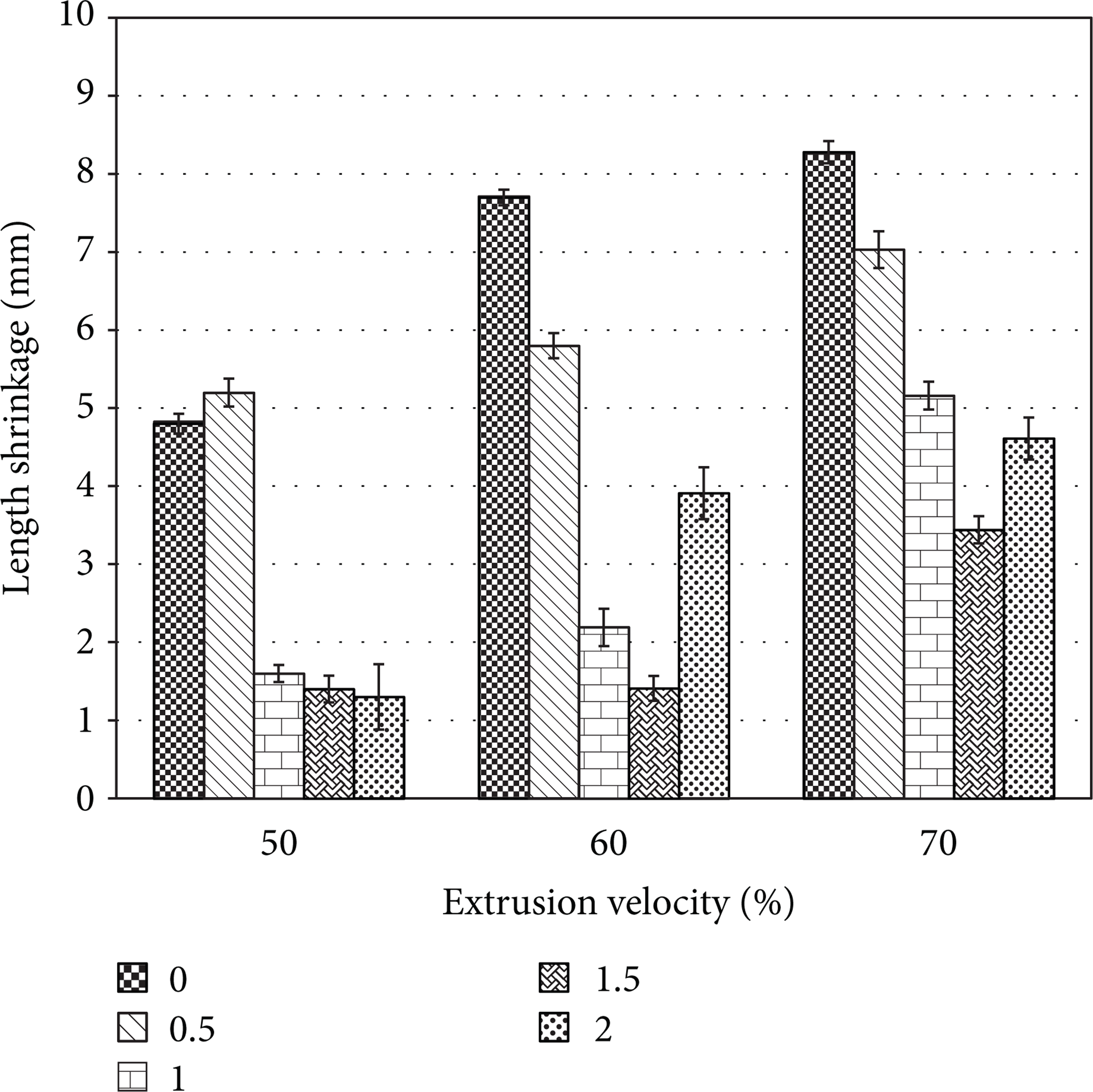
Variations in parison length shrinkage back for all foam cases studied (0 wt.%, 0.5 wt.%, 1.5 wt.%, 1 wt.%, and 2 wt.%) and for the three extrusion velocities (V1: 50%, V2: 60%, and V3: 70%).
An increase in perimeter can be observed when raising the CFA loading. The diameter swell is a viscoelastic phenomenon and both diameter and parison shape are mainly influenced by hoop stress and elongation stress. This swelling is greatly triggered by the molecular weight distribution and the applied strain rate. Parisons with no CFA show less swell, are more viscous, and thus dissipate less irreversible energy due to their springy behaviour. The speed at which the parison is pushed not only affects diameter swell but also affects its shrinkage due to the fact that the molten polymer remaining in the die is shorter and therefore it has a shorter relaxation time which makes the degree of elastic strain recovery greater [26]. Results show that the perimeter becomes 42% bigger (Figure 6) when adding 2 wt.% of CFA with respect to nonfoamed HDPE.

Parison perimeter in cm versus wt.% CFA percentage for V2. Over each case studied, last stage of the parison formation: (a) CFA: 0%, (b) CFA: 0.5%, (c) CFA: 1%, (d) CFA: 1.5%, and (e) CFA: 2%.
Other phenomena that can be observed are necking and sagging. The longer and thicker the parison is, the more emphasized these phenomena are. Sagging takes its name because of the sag-shaped the parison acquires due to its suspended weight below the die, which is the thinning of the parison under its own weight while it is extruded. It increases with a growth in the parison weight and a decrease of the cross-sectional area of the melt at the die exit. This cross-sectional reduction at the die exit is called necking. Both are influenced by gravitational forces acting on the parison [27].
In addition, for a fixed weight percentage of CFA, the parison suffers from shortening and swelling effects when the extrusion speed is increased. These effects can be observed in Figure 7. Variations in the final parison length must be perfectly known prior to blowing so as to be able to adapt a proper length for the mould dimensions to be used.
Variation in length and perimeter swelling for parisons with a 1 wt.% of foaming agent for three extrusion speeds: V1, V2, and V3.
The decrease in parison formation time when increasing CFA is considerable and essential when talking about industrial production rates. When increasing wt.% CFA formation time decreases. This effect is even more remarkable when raising also extrusion velocity. A slower formation time leads to a higher span time in the accumulator. These results are aligned with experimental parison work carried out by Yousefi et al. [18] which demonstrates that higher residence time in the accumulator may contribute to loosing polymer chains memory and in consequence leading to a lower swell. In our results, for V1 there is a maximum time saving of 19.5 seconds for 2 wt.% CFA, which means that the process becomes double efficient. For higher extrusion speeds these rates are surpassed and time formation becomes stable for a lesser amount of foaming agent, reaching the saturation point for this parameter with 1.5 wt.% CFA. The process becomes twice faster for V3, decreasing 24.5 seconds, and three times faster for V2 saving the sum of 34 seconds per parison with a total cycle time of 14 seconds. This fact is due to the effect of CFA, decreasing the melt viscosity and easing the flow throughout the die during the parison formation, which takes place faster.
An increase in wall thickness of about 20% occurs due to the expansion of the gas. Bigger size of bubbles can be appreciated for higher amount of CFA. Cases over 1.5 wt.% of CFA seem oversaturated and the cellular structure of the foam is degraded due to bubble coalescence, as can be observed in Figure 8.

Detailed cut of the parison wall for V2, being (a) 0 wt.% CFA, (b) 0.5 wt.% CFA, (c) 1 wt.% CFA, (d) 1.5 wt.% CFA, and (e) 2 wt.% CFA. Parisons were cryogenically fractured.
The main drawback of porosity during parison formation is that it causes a reduction of the load-bearing area and a reduction of the strength of the polymeric matrix which plays a crucial role supporting the weight of the parison itself. Exceeding the maximum wt.% CFA load used on this research may cause a premature rupture of the parison. A higher amount in chemical foaming agent leads to more nucleation points and larger porosity expanding the volume of the parison (Figure 9). For this reason it is essential to find out the limit amount of wt.% CFA for which foaming contribution is still advantageous for the process. For the blowing of the container a 1 wt.% CFA was determined as the appropriate amount of foaming agent. Extrusion velocity slightly seems to affect parison wall thickness for all cases studied.
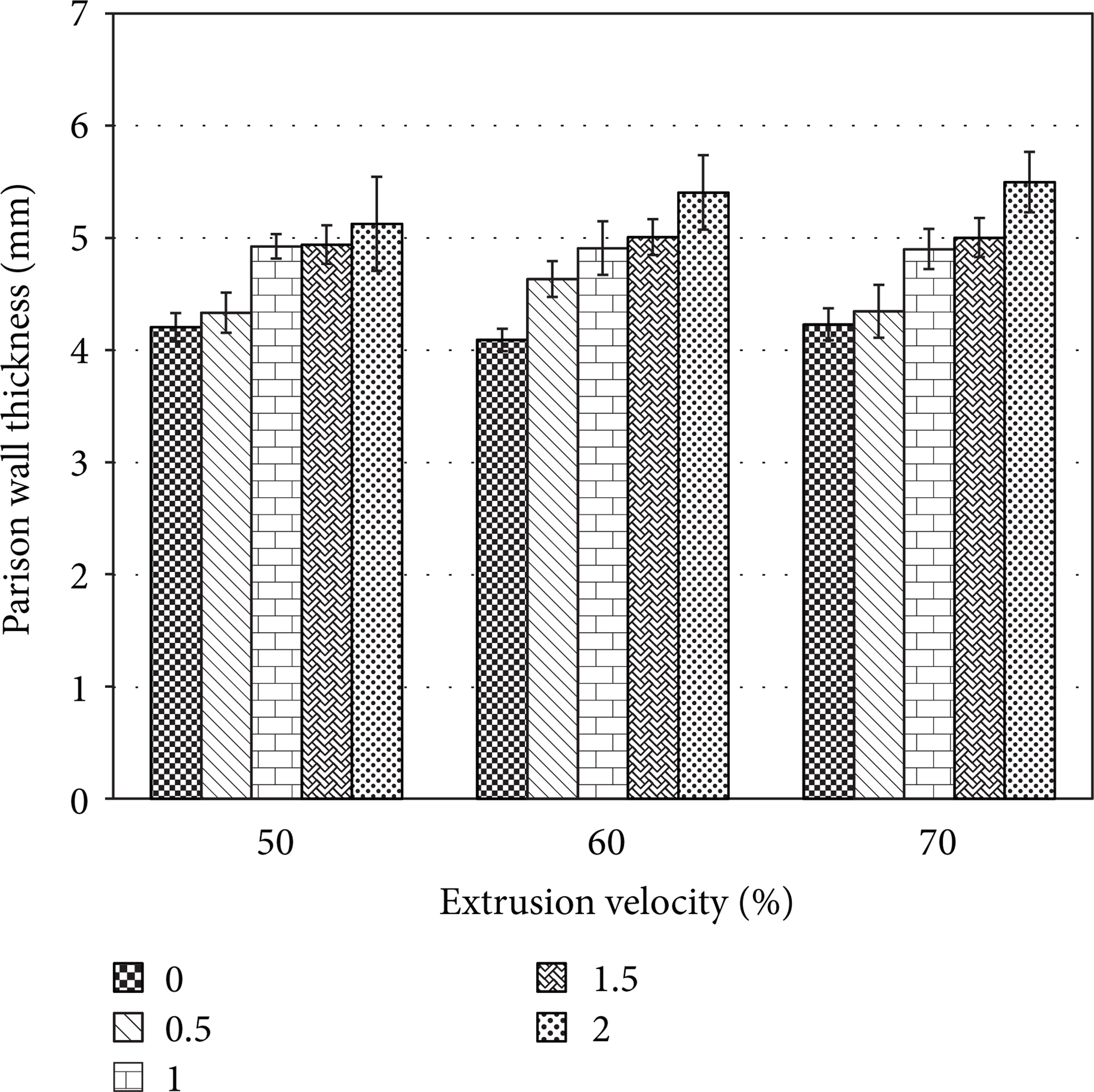
Variations in parison wall thickness for all foamed cases (0 wt.%, 0.5 wt.%, 1.5 wt.%, 1 wt.%, and 2 wt.%) and the three extrusion velocities (V1: 50%, V2: 60%, and V3: 70%).
4. Container Results and Discussion
Simulated blown containers were compared with experimental results. Simulations were performed introducing as much known parameters as possible from the characterized foamed parisons and varying the extrusion blowing pressure for two cases: 0.3 MPa and 0.7 MPa. This comparison allowed us to know the accuracy of the simulation tool for the blowing process. Corner thickness is the most critical part of the sample. As can be observed in Figure 10 which shows the simulated captures, thickness is not homogeneous within the perimeter of the container since the mould is not symmetric and the parison used had constant thickness with respect to length. Cross sections taken from the top, bottom, and medium parts of the container are shown in Figures 10(d), 10(f), and 10(h). The parison data used for the blowing simulations has been modelled to be very similar to the real foamed one, considering its real and apparent density taken from the initial characterization parison trials for 1 wt.% CFA and V2 conditions.

Simulation of the extrusion blown container for 1 wt.% of CFA and V2. Whole containers blown at different pressures (a) 0.3 MPa and (b) 0.7 MPa. Details from the simulated container blown at selected pressure (0.7 MPa): (c and d) refers to cross section from the top corner, (e and f) refers to cross section from the middle section and (g and h) refers to cross section from the bottom corner.
Batches of 10 containers per case studied were weighed and cut and their wall thickness was measured. Two different blowing pressures were applied (0.3 MPa and 0.7 MPa) in order to study the differences induced by this parameter in the blowing stage. Parison parameters for container manufacturing were as follows: extrusion speed was fixed at V2 (60%) for all container trials and containers were blown moulded for parisons with 1 wt.% CFA and without CFA. Table 2 shows the average in weight and deviation for the four blown cases. As it was expected, foamed containers are lighter than unfoamed ones. The average reduction in weight per part is close to 15% when adding 1 wt.% of CFA. Concerning pressure variation, as it was expected, it barely seems to affect weight containers.
Container weight in grams for 0.3 MPa and 0.7 MPa of blowing pressure and for 0 wt.% and 1 wt.% of CFA.

In Table 3 simulated results and experimental results of the wall thickness for different areas of the container have been included. Measures have been taken from the central line of the wall and also from the top and bottom corners. Containers blown at 0.7 MPa are slightly thinner than those blown at 0.3 MPa due to the higher air pressure force against the part walls which flattens the bubbles. Simulated results, although within a range, were quite close to the experimental results, obtaining the highest deviation from the real values for results measured in the top corners. In addition, measurements of wall thickness made for 0.3 MPa pressure blown container show higher deviations due to the irregular surface induced by bubbles.
HDPE + 1 wt.% CFA container blown wall thickness results in mm.

Main differences between the simulated results and the experimental ones may be due to the viscoelastic behaviour of the material. Ansys Polyflow allows simulating the whole blowing stage but not a thorough definition of the parison despite introducing all the material behaviour parameters. For this reason it is essential to have a well-defined parison, which in our case, has been fully characterised in the first stage of this research. However, the simulations performed must be taken as guiding container results and final fine-tuning adjustment of parameters must be done on experimental trials.
Another appreciable outcome in foam-blown extruded parts is the aesthetical quality improvement achieved on its surface. Foamed containers show a very regular, homogeneous, smooth, and less bright surface, which helps to hide flaws and imperfections providing a better appearance to the surface. Even drawings appear more defined and clearer in foamed parts, due to the expansive effect of the CFA gas that helps the air pressure of the blowing stage to push the material against the mould. The blowing pressure applied can be considered very relevant to the final blown part because it highly affects the surface quality. This difference between both containers blown at different pressure (0.3 MPa and 0.7 MPa) can be appreciated in Figure 11.
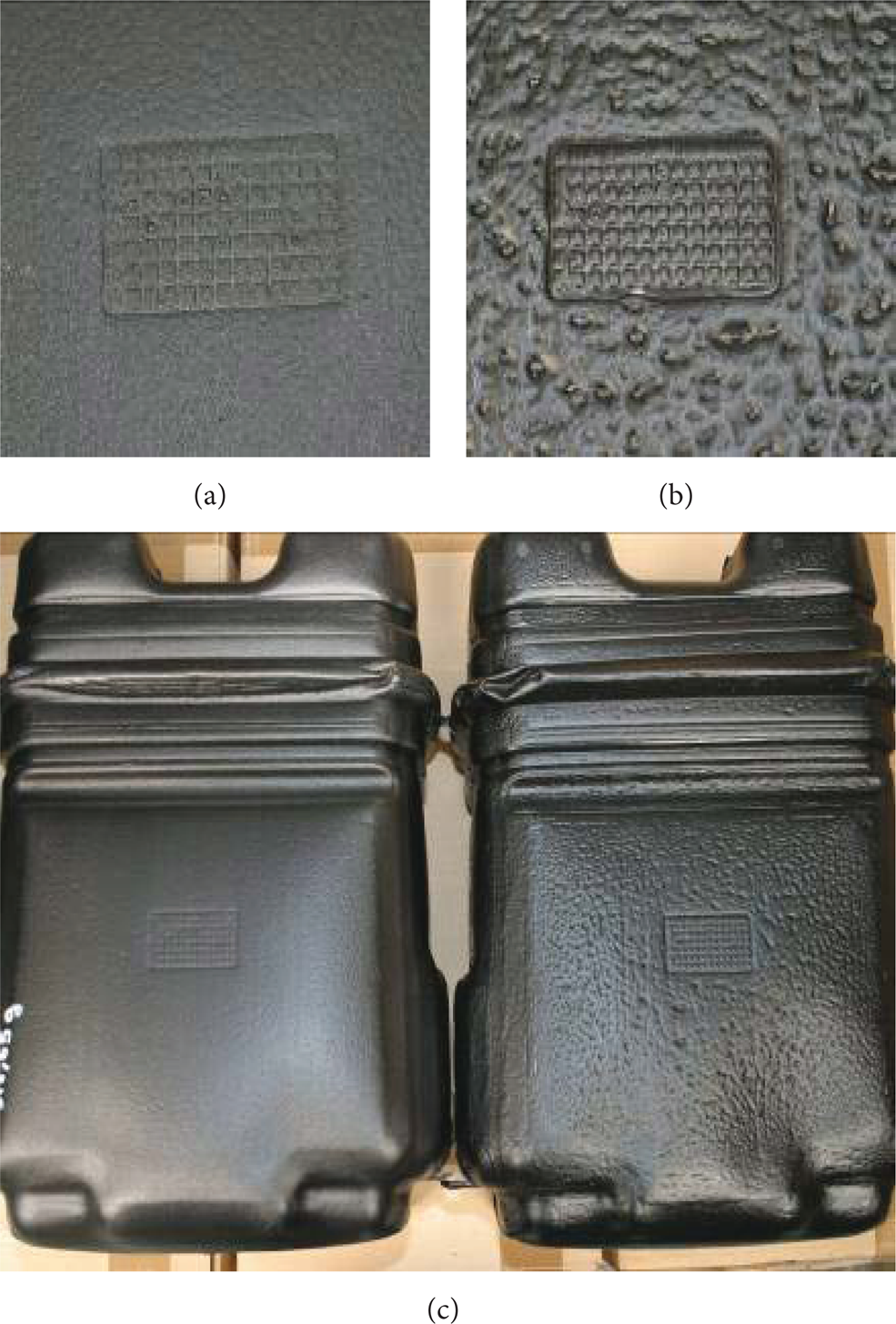
Containers with 1% CFA: (a) shows a drawing for a 0.7 MPa blown container, (b) shows the same blowing for a 0.3 MPa blown container, and (c) shows both containers placed side to side.
5. Conclusions
The present study represents an industrial approach focused on the experimental study of the parison formation in a blow extrusion process and how it affects the real industrial process and manufactured parts. The lack of studies and literature related to the study of the parison formation on blow extrusion processes makes the developed methodology very interesting for the manufacturing of lightweight parts using a fast and inexpensive tool. Moreover, it has been demonstrated that it is possible to run a correct simulation of the foamed blown container by an appropriate characterization of the parison. On the first experimental part of this research, a detailed study of the foamed parison extrusion was performed while in the second part manufacturing of a generic container was carried out, studied, and finally compared with a simulation of the process.
It was observed that the porosity induced by the CFA in the melt matrix forces the parison to grow in its three dimensions, producing a swollen, larger, and thicker parison. The foaming effect reduces the length shrinkage effect of the parison, as well as its formation time and weight (around 15%). These are advantageous points for extrusion blowing parts producers because they directly reduce the use of raw material which has both economic and environmental considerations, as well as increasing production rates with significant improvements in quality aspects. In addition, the influence of the extrusion speed parameter on the extrusion process has been studied. For a higher speed processing it was observed that the length of the parison is shorter but length shrinkage increases. As it was expected the total cycle time of the extrusion process is reduced.
Conflict of Interests
The authors declare that there is no conflict of interests regarding the publication of this paper.
Footnotes
Acknowledgment
This research has been partially funded by the Spanish Ministry for Economy and Competitiveness (MINECO) under the program INNPACTO, reference: Nemia-Pack, IPT-2011-1285-420000.