
Abstract
The issue of uniform flow distribution has recently received growing attention for heat sinks design. In order to improve the flow uniformity and heat transfer capacity of a U-type heat sink, a multiobjective optimization design is presented based on the orthogonal experiment design method. Therefore, a computational fluid dynamics model is established, and then the flow fields and temperature fields are investigated. The results show that the distribution of the fluid into each parallel channel not only is a function of the flow conditions in the header but also is affected by the geometric size of the header and the parallel channels and that the optimum U-type heat sink based on orthogonal experiment design method can give uniform flow distribution.
1. Introduction
There is a higher and higher heat flux density for the electronic equipment, and it often reaches up to 100 W/cm2; thus liquid cooling is becoming more and more popular for its high heat transfer efficiency compared with that of air cooling [1, 2].
Generally, for the liquid cooling heat sink, there are serpentine channel, serpentine-parallel channel, Z-type parallel channel, U-type parallel channel, and so forth. Among these, the U-type parallel channel heat sink has the advantages of compact structure and low pressure drop; so it is widely used in the heat transfer field [3, 4]. However, the obvious disadvantage of it is that the fluid distribution from a header into the parallel channels is often not uniform which could not only greatly decrease the heat transfer capacity but also lead to local overheating of the equipment. In 1970, Duncle and Davey [5] proved that there is nonuniform flow distribution in the U-type parallel channel used in the solar collector. After this, Chiou [6] proved that the whole efficiency will decrease 2%~20% if there is nonuniform flow distribution in the solar collector. Lu and Wang [7] researched the effect of the inlet location on the heat transfer capacity of U-type parallel channel heat sink and claimed that not uniform flow distribution had great influence on its heat transfer capacity. Therefore, the issue of uniform flow distribution has recently received growing attentions.
Subsequently, some researchers investigated the influence factor of flow distribution uniformity of the U-type parallel channel by the theoretical model, simulation, and experiment. For example, Bassiouny and Martin [8, 9] established the theoretical model of the fluid flow and pressure drop of a plate heat exchanger with U-type parallel channel and claimed that some factors affect the flow uniformity, such as channel sizes, shape, and inlet velocity. Wang [10–13] also built a theoretical model about the fluid flow and pressure drop for the U-type parallel channel fuel cell stack based on the mass and momentum conservation law. During the modeling process, the friction between the fluid and the channel wall is considered in the model, so it is more accurate than the previous model. But there are many unknown parameters, so it does not have the analysis solution. Maharudrayya et al. [14, 15] employed the computational fluid dynamics (CFD) to investigate the flow distribution and pressure drop of seven kinds of channel shapes. Wang et al. [3, 16] also studied the fluid flow uniformity and pressure drop with the help of the experiment and CFD, and their results showed that some factors affect the fluid flow uniformity, such as the channel shape, fluid input velocity, and fluid hydraulic diameter. In addition, as a result of the experiment study, they claimed that the input shape of the channel will affect the flow distribution largely. Huang and Zhu [17] established the fluid flow model of multilayer U-type parallel channel heat sink and proved the consistency between the theoretical model and the CFD. Their results showed that the channel shape has great effect on the flow distribution. Since the 1990s, Professor Yang, Xi'an Jiaotong University, began to study the flow distribution in the parallel channel using the discrete mathematics [18].
As stated above, many researchers concentrated on the flow distribution of U-type parallel channel devices, such as fuel cell stack, condenser, evaporator, and solar collector, and not on the heat sink. Secondly, although some researchers established the theoretical model of the flow distribution and pressure drop for the U-type parallel channel, there are many unknown parameters in the model which cannot give the definite solution, so that it is difficult using the theoretical model to design the U-type parallel channel. Lastly, these models are only used to discuss the flow distribution, not about the heat transfer capacity.
This paper intends to investigate the flow distribution and the heat transfer capacity from the geometric structure and optimize the U-type parallel channel heat sink and targets to improve flow uniformity and heat transfer efficiency of liquid cooling U-type parallel channel heat sink.
In recent years, researchers have carried out some structural design and optimization of liquid cooling heat sinks [19, 20]. For instance, in 2006, Hilbert et al. [21] performed multiobjective design optimization concerning the blade shape of a heat exchanger, considering the coupled solution of the heat transfer processes. In 2014, Xie et al. [22] carried out numerical investigation on microchannel heat sink to study the laminar fluid flow and thermal performance based on constructal theory. But these optimization objectives are heat transfer capacity, not the flow distribution.
For the moment, there are some widely used algorithms which can be used to perform multiobjective optimization design, such as particle swarm optimization (PSO) algorithm, genetic algorithm, ant colony algorithm, and artificial immune system [23, 24]. But for heat sink design, the orthogonal experimental design method is more suitable because its objective functions cannot be expressed by the equations. In this research, a multiobjective optimal design of a U-type parallel channel heat sink is proposed based on the orthogonal experimental design method, which is targeting improving the fluid flow uniformity and reducing the overall thermal resistance, with four design variables: the number of channels, channel width, channel height, and header size.
This paper is organized as follows: Section 1 introduces the background of this research work; Section 2 discusses the structural modeling of a U-type parallel channel heat sink; Section 3 discusses the effect factor of fluid flow uniformity; Section 4 discussed the optimization design based on the orthogonal experimental design method; Section 5 concludes this paper.
However, until now, the general methodology for improving the flow distribution at header-channel junctions still lacks due to the complex interactions amid geometrical configurations and inlet flow conditions at the inlet header.
2. Structural Modelling of the U-Type Parallel Channel Heat Sink
As shown in Figure 1, the U-type parallel channels heat sink with inlet and outlet rectangular headers and square cross-section is composed of the base plate and cover plate, which has N channels with width W c , (N − 1) fins with width W r , and with depth H c . For the heat sink, from the inlet to outlet, the fluid flow path (through these parallel N channels) looks like an alphabet “U,” so it is named as U-type parallel channel heat sink. The arrows under the base plate stand for the uniform heat flux that the heat sink is subjected to. The three-dimensional figure of the heat sink except for the top cover is shown in Figure 1(b), and its structure dimensions are L*W*H = 100 mm*100 mm*12 mm. The other related parameters are listed in Table 1. The heat sink is made of aluminum and the fluid in it is water, and their thermal parameters are shown in Table 2.
The initial geometric sizes of the heat sink.

Material parameters of thermal and physical properties.


The model of the U-type parallel channel heat sink.
In order to establish the flow and heat transfer model, the following assumptions are made.
Fluid flow is incompressible and laminar and the transport process is steady.
The gravity effects and radiation heat transfer are neglected for fluid flow.
Both the thermophysical properties of fluid and heat sink are constant.
The viscosity dissipation is negligible.
With the above assumptions, the governing equations for this conjugated heat transfer problem can be described as follows.
The flow distribution across the channel is solving mass-continuity and momentum equations along the length of the input and output. Fluid flows between the input and the output headers via the channels that connect them. Thus, the conservation equations must accommodate the distributed mass loss from the input header and the mass increase in the output header.
Continuum equations for conservation of mass, momentum, and energy, respectively, for the convective heat transfer in liquid cooling heat sinks can be written as follows:

where C p represents thermal capacity, ρ denotes density (kg/m3), μ represents dynamic viscosity (Pa·s), k f denotes thermal conductivity of the fluid, and k s denotes thermal conductivity of the heat sink.
The above equation combined with appropriate set of boundary conditions can be solved, and the according results are obtained as shown in Figure 2. In Figure 2(a), the color line stands for the fluid flow direction, and the darker the color, the faster the fluid velocity. Therefore, the flow rate is the lowest in the first channel and gradually increased as the channel number increased. The results can be explained because of the jet flow phenomenon. Also, because of the high velocity in the last channel, the highest temperature locates at the last channel as shown in Figure 2(b). Therefore, there are obvious flow nonuniformity and overheating phenomena in the U-type parallel channel if the geometric parameter and flow rate are not suitable.
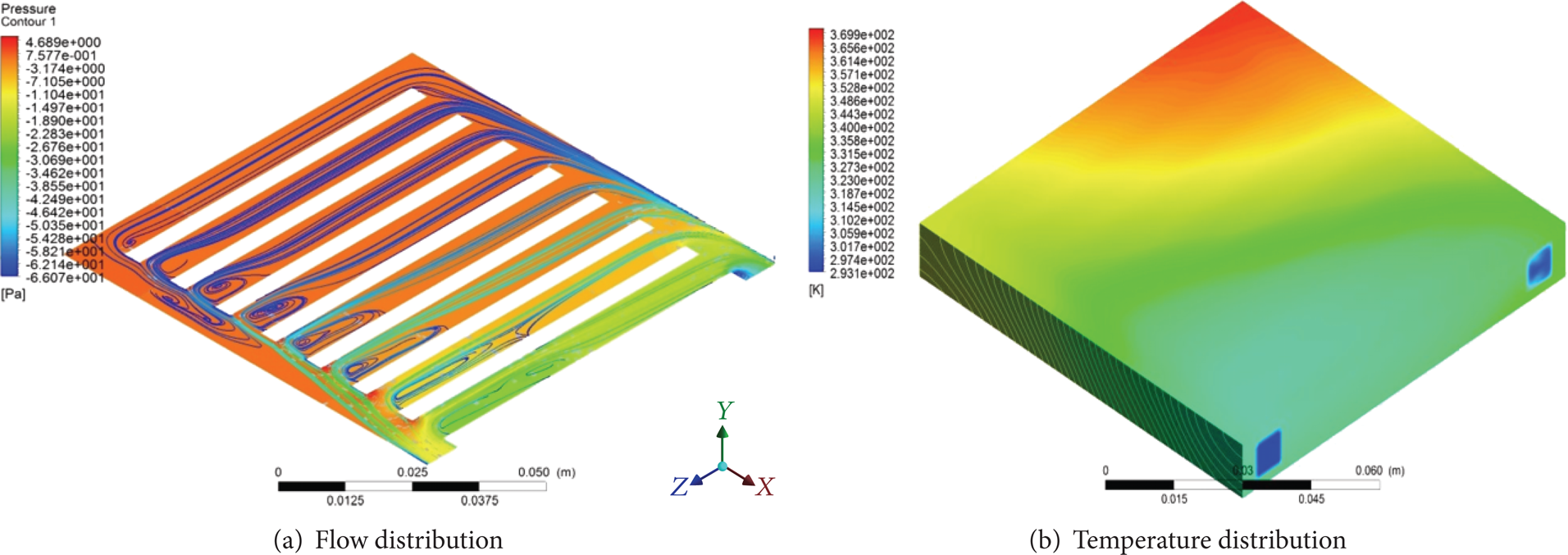
Flow and temperature distribution.
3. The Effect of the Geometric Parameters
In order to evaluate the flow distribution, the coefficient of the flow uniform is defined. For counting the flow distribution among the parallel channels, the dimensionless parameters β
i
,

where β i denotes the flow ratio for ith channel, Q i represents volume flow rate for ith channel (m3/s), and Q is total volume flow rate (m3/s). To characterize the influence, Chiou [6] had used the concept of standard deviation to define the nonuniformity, K m , as follows:

where N is the number of total channels in the parallel flow heat sink and
In order to evaluate the heat transfer capacity of the heat sink, the thermal performance is evaluated by the total thermal resistance of the heat sink. The total thermal resistance R t can be defined as follows:

where Tmax is the highest temperature of the heat sink, Tin is the coolant inlet temperature, q w is the uniform heat flux added to the heat sink, and A = L*W is the base plate area of the heat sink.
The literature survey reveals that the flow distribution in the U-type parallel channels is very complex. Distribution of the flow into each parallel channel not only is a function of the flow conditions in the header, but is also affected by the geometric size of the header and the parallel channels. However, the flow distribution problem may become even more critical in modern compact/microheat sinks because severe flow maldistribution could lead to overheating and cause entire failure of the thermal system. In this regard, the purpose of this study is to investigate the flow distribution subject to small and parallel channels applicable for compact heat sinks. The effects of channel and header sizes are also investigated with various area ratios for optimizing the flow distribution. For comparison and better physical insight into the flow distribution, commercial software is utilized to simulate the flow fields and temperature fields.
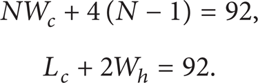
The nonuniform distribution in parallel channels could be related to the stream velocity in the header, size of the header, diameter of the channel, location and size of inlet port to the header, and the like. Thus, it is very imperative to understand the flow distribution phenomena in the header and parallel channels as far as performance is concerned. The relationships between these geometric parameters, such as the width of channel W c , the number of channel N, the length of channel L c , and the header width W h , meet the following equations:
The mass flow rate in the inlet is fixed as 12.777 g/s, the temperature of the water in the inlet is 293.15 K, and the uniform heat flux is 5 W/cm2. Thus, the above governing equation (1) for the described problem can be solved numerically using the finite volume method (computational fluid dynamics (CFD)). For a given combination of parameters, the field solutions are calculated by an iterative scheme. Details of the solution procedure are not repeated herein. To obtain enhanced accuracy in the numerical computations, the independence of grid points was examined first. In this work, the grids were arranged to be nonuniformly distributed in both the cross-sectional and the stream directions to account for the uneven variations in field properties. Based on the solutions, a series of geometric parameters are discussed to study the flow distribution and heat transfer characteristics as follows.
3.1. Effect of the Channel Number N
From (5), it can be concluded that there is a one-to-one relationship between channel number N and W c . When the channel number is 6, 8, 10, 12, 14, and 16, respectively, the width of the channel W c will be 12 mm, 8 mm, 5.6 mm, 4 mm, 2.857 mm, and 2 mm, respectively. At this moment, several CFD simulation models can be established according to the above parameters, and then the according simulated results can be obtained as shown in Figure 3. Here, Figures 3(a)–3(f) represent the fluid distribution for different channel number. The according fluid distribution data in every channel for the models can be obtained as shown in Figure 4(a) and the thermal resistance in every channel can also be gotten as shown in Figure 4(b). As seen from this figure, it can be concluded that the fluid distribution is becoming more and more uniform as the channel number N increases. Therefore, the narrower channel is desirable for the uniform fluid distribution. At the same time, the thermal resistance is becoming smaller and smaller as channel number N increases, and this is also desirable for better heat transfer.

Fluid distribution for different channel number N.

The relationship between fluid flow, thermal resistance, and channel number N.
3.2. Effect of the Channel Length L c
Again, according to (5), it can be found that there is a one-to-one relationship between the channel length L c and the width of header W h . When Channel length L c is 74 mm, 76 mm, 78 mm, 80 mm, 82 mm, and 84 mm, respectively, the flow distribution and thermal resistance are shown in Figure 5. It can be seen that from this figure, channel length L c has little effect on the fluid flow uniformity but obvious effect on the thermal resistance.
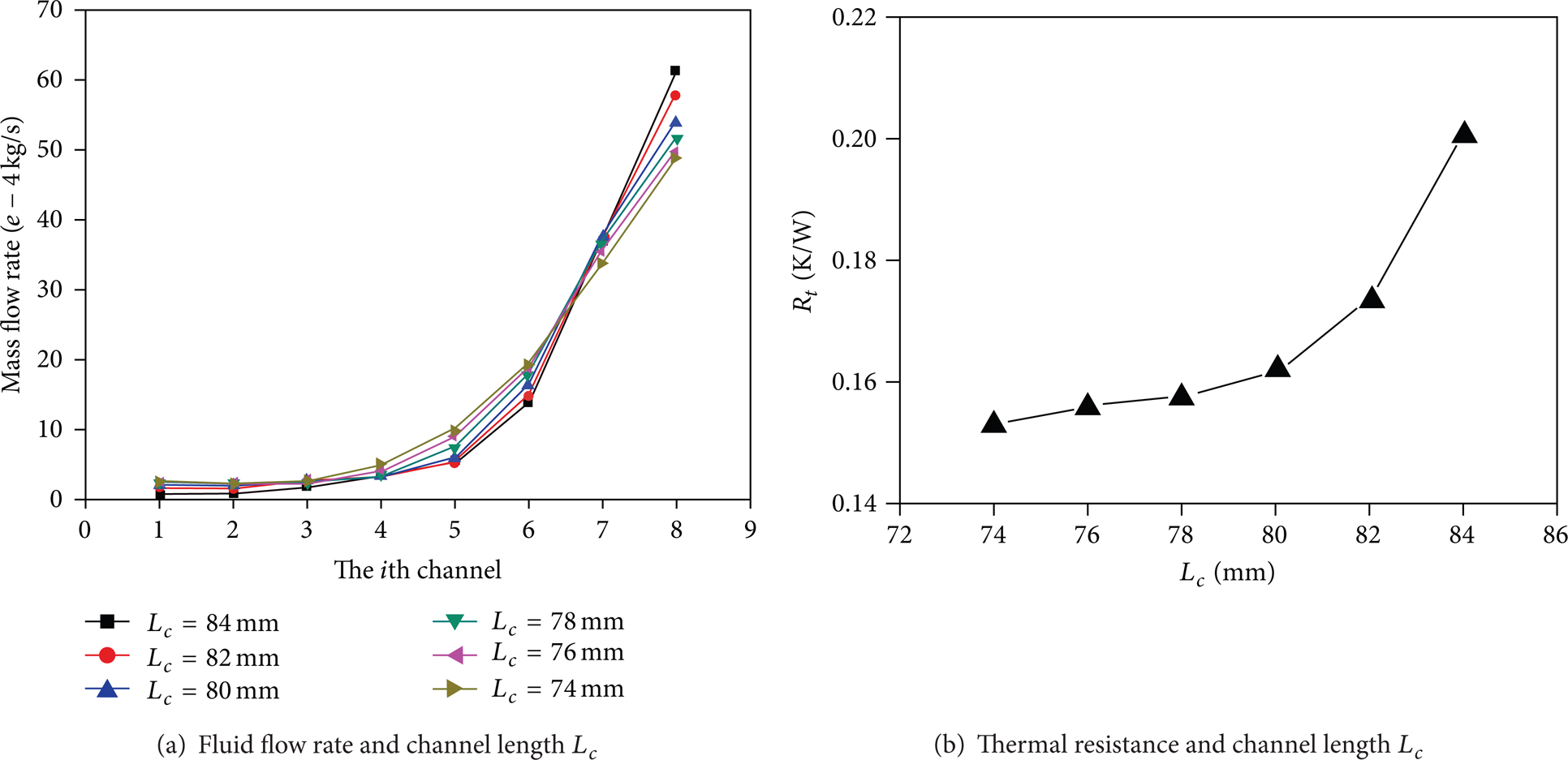
The relationship between fluid flow, thermal resistance, and channel length L c .
3.3. Effect of the Channel Height H c
When channel height H c is 4 mm, 5 mm, 6 mm, 7 mm, 8 mm, and 9 mm, respectively, the flow distribution and thermal resistance are shown in Figure 6. It can be seen that channel height H c has little effect on the fluid flow distribution but obvious effect on the thermal resistance.

The depth of channel H c on the flow distribution and total thermal resistance.
4. Optimized Design of the U-Type Parallel Channel Heat Sink
According to the above analysis, it can be found that the width of the parallel channel has great effect on the flow distribution and thermal resistance. However, the parallel channel length L c and the height H c have little effects on the flow distribution, and they only affect the thermal resistance.
In order to realize the uniform flow distribution and improve the heat transfer capacity, the flow uniformity coefficient K m and the highest temperature Tmax are selected as the objective parameters.
Generally, a multiobjective optimization problem can be written as shown in (6), subject to equality constraints G i (x), as given in (7), and inequality constraints H i (x), as given in (8). Here, J is the number of objective functions, M is the number of the equality constraints, I is the number of the inequality constraints, x = [x1, x2, …, x K ] is the decision variables vector, and K is the number of the variables.
Minimize


All vectors satisfying (7) and (8) are named as the solution set, in which the decision variables set of x* = [x1*, x2*, …, x k *] yields the optimum values of all the objectives.
In order to realize the optimize design, the orthogonal experiment design method is selected, and it is a kind of optimization method which uses the orthogonal table to do some experiment to select the optimum combination between variables. The design process is shown in Figure 7.
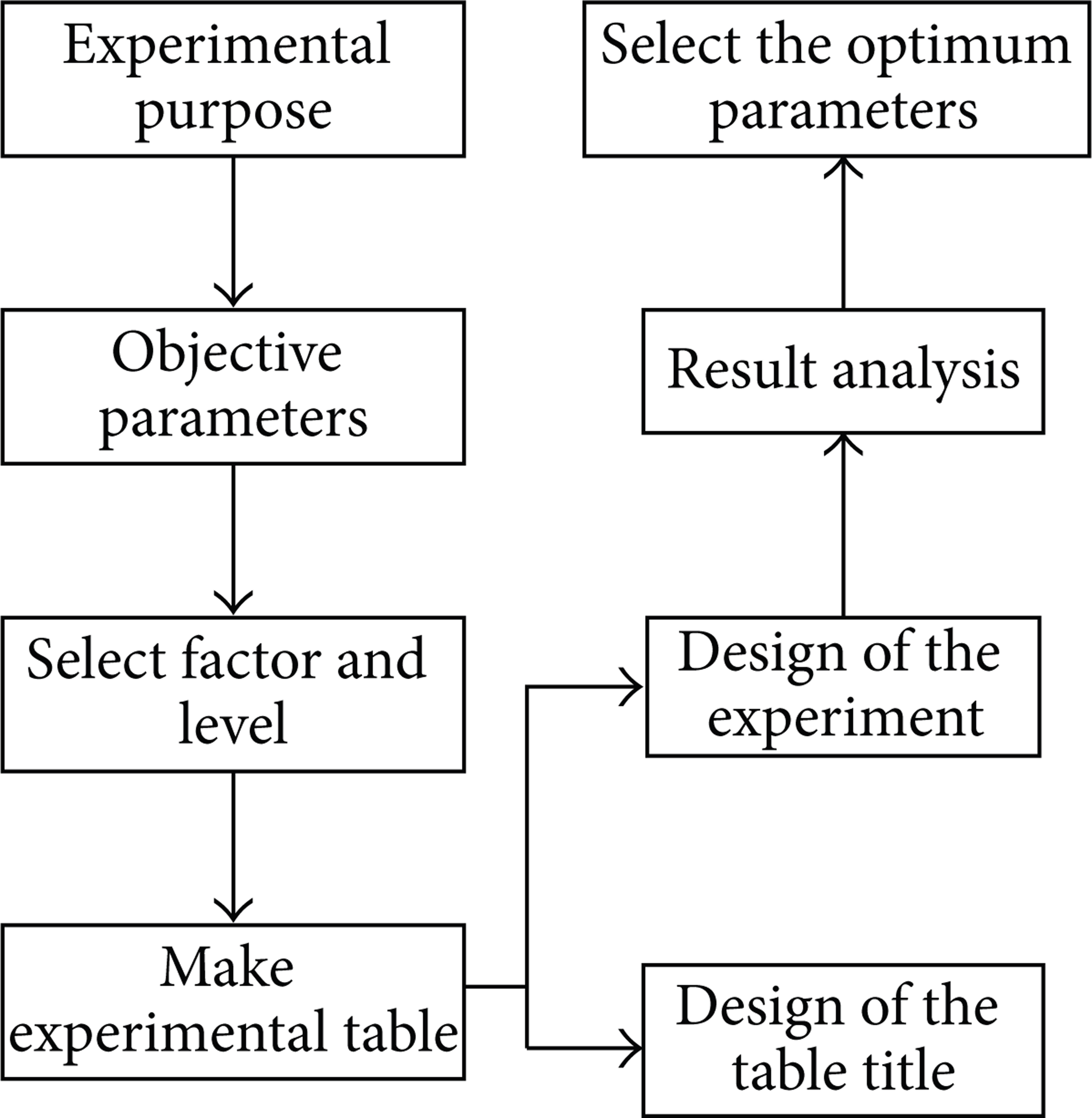
The basic process of the orthogonal experiment design method.
The purpose of the experiments is to improve the uniformity of flow distribution and enhance the heat transfer capacity of the heat sink. One of the evaluation parameters is the coefficient of flow uniformity K m , and the smaller the K m , the better flow uniformity; when the K m equals zero, the flow distribution becomes perfectly uniform. The other one of the evaluation parameters is the highest temperature of the heat sink Tmax , and the lower the Tmax , the better the heat transfer capacity of the heat sink.
For the test, the geometric parameters, such as N, H c , L c , and r (ratio of the inlet width Win and the bottom width W h of the header), are selectedas factors, labeled as A, B, C, and D, respectively. Thus four factors and four orthogonal test levels can be carried out and made up L16(45) orthogonal table, like Table 3. When the interaction between the various experimental factors is ignored, the results of the orthogonal experiment are listed in Table 4. Here, K j (j = 1,2, 3,4) represents the sum of the experiment result for jth level of each factor. Small input trapezoid heat sink is shown in Figure 8.
Variable factors and level of the orthogonal test.

The text methods and the results of orthogonal test.

The structure of the small input trapezoid heat sink.
From the experiment results of Table 4, the following results can be obtained.
The relationship between the objective parameter and the variable can be shown in the Figure 9.
The optimal combination and the order of factors on the objective parameters based on the range R and the minimum of the average
The optimal combination and the order of factor.

The relationship between objective parameters and variables.
Therefore, the optimum combination is A4B4C1D1; namely, the parallel channel number N is 16, the channel depth H c is 8 mm, the parallel channels length L c is 78 mm, and the ratio r is 1: 1. At this condition, the coefficient of flow uniformity K m is 3.7455 and the highest temperature of Tmax is 323.4 K. Thus the optimal combination is A4B4C1D1.
Based on the optimum combination, the flow distribution of the U-type parallel channel heat sink is shown in Figure 10. Here, it can be seen that the flow uniformity has great change compared with the original model. The temperature distribution of the U-type parallel channel heat sink is shown in Figure 11 after optimization. It can be seen that the highest temperature is 323.4 K which decreased to 46.5 K. These results showed that the orthogonal experiment design method can be used to improve the flow uniformity and heat transfer capacity of a U-type heat sink.

Comparison results of optimization.

Temperature distribution after optimization.
5. Conclusions
In this paper, the single phase flow distribution and heat transfer capacity in compact U-type parallel flow heat sink are investigated by numerical simulations subject to various operating conditions. Under isothermal condition, the experimental investigation on the effects of some important geometric parameters on the low distribution and heat transfer capacity are performed. Based on the orthogonal experiment design method, these geometric parameters, such as N, L c , and H c , are optimized to get the optimum geometric combination. Accordingly, some conclusions are obtained as follows.
The channel number N has obvious effect on the flow distribution and heat transfer; however, channel length L c and height H c have little effect on the flow distribution and obvious effect on the thermal resistance.
Orthogonal experiment design method is used to carry out the multiobjective optimization. The optimization objective is the coefficient of flow uniformity and the highest temperature, optimization variable is channel number N, and length L c and height H c are the optimum parameters. The results showed that channel number N = 7 mm, channel depth H c = 8 mm, channel length L c = 78 mm, and ratio r is 1: 1 when the heat sink L*W*H = 100*100*12. At this moment, the coefficient of flow uniformity K m is 3.7455, and the highest temperature Tmax is 323.4 K.
The flow uniformity and heat transfer capacity of the U-type heat sink can be improved significantly, which also illustrates that the orthogonal experiment design method can be used to deal with the multiple discrete variable optimization problems.
Conflict of Interests
The authors declare that there is no conflict of interests regarding the publication of this paper.
Footnotes
Nomenclature
Acknowledgments
The authors would like to thank the National Natural Science Foundation of China (61106107) and the Postdoctoral Foundation of China (2014M552333) for their support.