
Abstract
Localization in a wireless sensor network (WSN) becomes important for many modern applications, like landslide detection, precision agriculture, health care, and so forth. The more precise the position of an anchor node is, the more accurate the localization of a sensor node can be measured. Since the Global Positioning System (GPS) device cannot work properly indoor, some existing localization methods configure anchor nodes in a manual fashion. However, neither applying GPS modules nor manually configuring anchor nodes is suitable for a WSN and especially artificial errors of manual configuration may be propagated and affect the results of localization. In this paper, we propose an alternative method to estimate anchor node locations in an indoor environment. We collect the Received Signal Strength Indicator (RSSI) data from the anchor node when human is walking around them. Meanwhile, we use a wearable IMU-camera device to assist the moving trajectory estimation. We implement a monocular Visual Odometry with a human walking model to estimate moving trajectories. An Unscented Kalman Filter (UKF) is used to estimate the anchor node location by fusing the RSSI data and moving trajectory. The experiment results show that the proposed method has lower estimation error when locating anchors.
1. Introduction
Wireless communication and MEMS IC technology have enabled the development of low-cost, low-power, and multifunctional sensor nodes. A wireless sensor network (WSN) containing large numbers of sensors can be applied to monitoring and controlling homes, buildings, cities, rivers, forest, and so forth. [1–3]. Self-localization capability is necessary for WSN sensor nodes, especially when they are deployed randomly or moved after deployment. To reduce the implementation cost and energy consumption, special sensor nodes, called anchor nodes, are installed with known positions [4–11] to localize a group of sensor nodes in the vicinity. The simplest way to determine the positions of anchor nodes is to use Global Positioning System (GPS) devices [4, 12–18] or is to be manually measured [8, 10, 11] in advance. However, GPS devices fail to offer precision in an indoor environment or GPS-denied area (poor signal reception). Manual measurement is a tedious and error-prone process that is unsuitable for indoor sensor networks. Hence, other localization technologies to estimate the locations of anchor nodes become very important.
There are two approaches of WSN localization technology: (1) range-based and (2) range-free [19] approaches. A range-based approach relies on the distance or the angle information between anchor nodes to estimate locations by using Trilateration, triangulation, or multilateration algorithms. These locating schemes require additional devices to measure the distance or the angle information from anchor nodes. A range-free approach estimates locations using network connectivity information from their direct neighbors. However range-free approach suffers from heavy message transmission cost to collect the connectivity information and high computational cost to estimate locations of anchor nodes [20–22].
The Trilateration algorithm can be used to compute the anchor node locations based on pairs of moving Received Signal Strength Indicator (RSSI). Hansson and Tufvesson [23] provided a trajectory estimation method using the inertial measurement unit (IMU) sensors in a smartphone (accelerometer, gyroscope, and magnetometer) to obtain an orientation tracker, a step detector, and a walking path recorder of a user. However, the trajectory diverges easily without dead reckoning due to the bias of IMU sensors. Pescaru and Curiac [24] use video and compass information fusion scheme for anchor node localization. The video image relies on the automated object recognition algorithm to find the geographically located referential objects. The compass can provide the orientation of the anchor node's camera. The fusion of these two sensors' information can compute the reference points bearing. However, the digital compass module subjects to hard and soft-iron distortions. The paper has no mention about the distortion effect to the experiment results.
The trajectory estimation [25–33] is commonly used in simultaneous localization and mapping (SLAM) and Visual Odometry (VO) researches [34]. In WSN, there is no need to use a map from SLAM to locate human position. Alternative VO [35] is the one that does not require infrastructure support. The VO is a vision-based technique which combines camera and IMU devices to provide trajectory estimation with scale. Corke et al. [32] showed that the camera and IMU have complementary advantages in many cases. In order to fuse the data from the camera and IMU, VO usually uses Kalman filter based method to predict and update the moving trajectory. For a nonlinear system, extended Kalman filter (EKF) and Unscented Kalman Filter (UKF) provide different ways to approximate higher-order terms [34]. Some papers [34, 36–40] analyze the accuracy and complexity between the EKF and UKF. Although the UKF has higher computational cost, [38, 39] show that the UKF has better accuracy than EKF in some cases. The VO with IMU support is possible to compute the scale without the need of a calibration pattern for camera [25, 27, 30, 31, 33, 41–43]. Designing a reference device that can be carried by human is the most attractive way to localize anchor nodes particularly in indoor environment. When it is applied on human, the signal-noise-ratio of the IMU sensor is small since the walking speed is slow. In other words, it is unlikely to obtain accurate velocity information from the acceleration integration and the performance of the scale estimation will be seriously affected.
In this paper, we propose a sensor fusion method to locate anchors in an indoor environment by using a wearable IMU-camera and a wireless sensor mounted on the center of human's waist for moving trajectory estimation. We can receive images, angular velocities, acceleration, and RSSI data from the IMU-camera and the wireless sensor. The proposed VO, which includes human walking model [44, 45], uses UKF to estimate the moving trajectory and human walking speed [46]. By measuring the RSSI data, it is then possible to localize the anchor nodes by a human walking around them. To validate the proposed approach, we consider the sensor noise and bias into our system and design several experiments to locate sensor nodes after obtaining the anchor positions by the proposed method.
The rest of this paper is organized as follows. Section 2 presents the proposed method which includes scaled moving trajectory estimation and anchor node localization estimation. Section 3 presents the hardware design. Section 4 is the experiment environment setup. Section 5 validates the proposed approach with experimental evaluations. Finally, the conclusion is drawn in Section 6.
2. Proposed Method
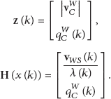
We assume that the sensor node and anchor node exist in two parallel planes illustrated in Figure 1, and the experiment environment setup is in Figure 2. A control server can receive the image, IMU data, and RSSI data from the sensor node which is composed of an IMU-camera and a RF sensor. The IMU includes triaxes gyroscope and triaxes accelerometer. The system design flowchart is shown in Figure 3. Considering the inconsistency of data sampling frequency, we adopt the loosely coupled [25, 27, 42] architecture in our sensor fusion method. The UKF based loosely coupled approach in our design includes scaled moving trajectory and location estimation of the anchor nodes. The first step uses image, angular velocity, and acceleration data to realize VO and human walking speed estimation. Then we combine the VO and human walking speed to implement the scaled moving trajectory estimation. The second step combines the attitude of the scaled VO and calibrated RSSI data to simultaneously estimate the IMU-camera moving trajectory and anchor locations by applying UKF.
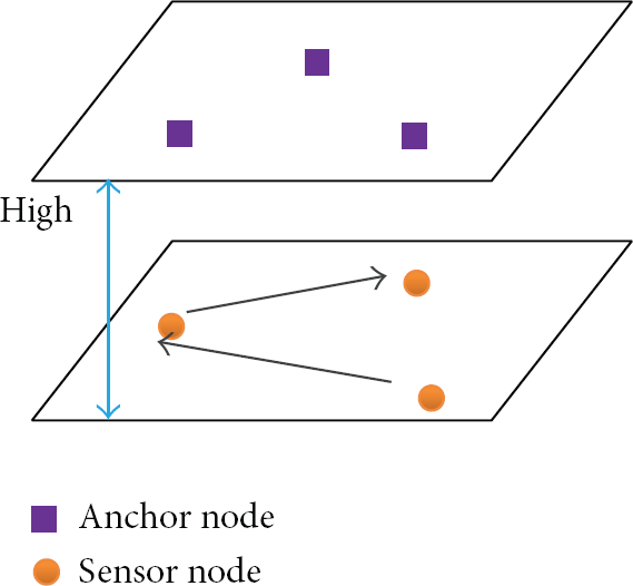
Anchor node and sensor node setup.

The schematic diagram of location.

System design.
2.1. Scaled Moving Trajectory Estimation
We use a calibrated IMU-camera to provide image, acceleration, and angular velocity data for scaled VO. The proposed scaled moving trajectory estimation includes (1) VO which combines image and IMU data, (2) human walking speed estimation which uses a kinematic model of human walking, and (3) scaled VO which combines VO and human walking speed estimation as shown in Figure 3. The VO uses the IMU data and image data to estimate the 3D locations of feature points and the IMU-camera pose. The human walking model uses the acceleration data from the IMU-camera to estimate the moving speed.
2.1.1. Visual Odometry
The proposed VO uses IMU-camera which we made to measure the moving trajectory. There are three coordinates in our VO method. We define the geometric coordinate between the IMU frame
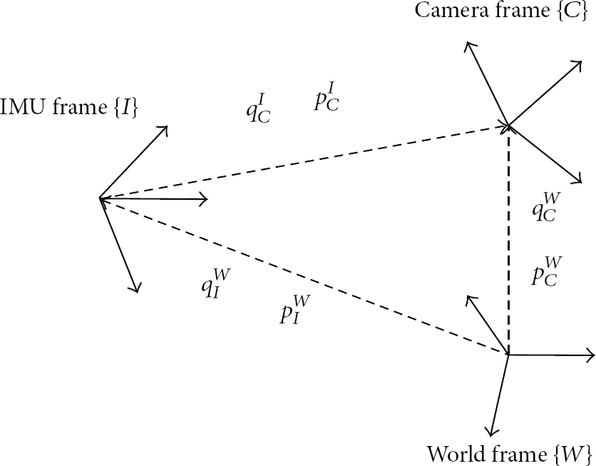
IMU-camera coordinates transition map.
The single camera provides scale-free position and rotation estimation with respect to world frame. We estimate the camera pose by using the algorithm of the 1-point RANSAC EKF-based monocular VO [28]. The camera is formulated by a perspective projection model with constant angular and linear velocity model. The state vector x of the filter is composed of camera state and estimated feature points where
The monocular camera pose estimation of [28] has to initialize the feature points which are immediately used in the camera ego-motion estimation from the bearing references. Civera et al. [47] use the inverse depth method for undelayed initialization of the feature points. Hence the feature points are initialized with a Gaussian prior depth estimation in inverse depth coordinates. The depth estimation can be refined by sequential observations of the feature points. Consequently, when the projection equation becomes linear, the representations of the feature points are converted to the Euclidean coordinates. The algorithm includes two steps: prediction and update. The state vector x is estimated by the camera motion model in the prediction step, and the state vector x can then update the observation of feature points in the next step. Between the prediction and update steps, outliers of feature points are rejected by using 1-point RANSAC.
2.1.2. Human Walking Speed Estimation
We use the kinematic walking model [44, 45] which considers the waist rotation effect. It avoids integration error of the accelerometer and provides the scale information. Assume that the leg rotates around a point G located below the ground during the stance stage; see Figure 5. The estimation method of the length of the right leg L’ in Figure 5 is presented in [44]. The estimation is based on the acceleration measurement at COM (center of mass) over a complete stance cycle. Considering the COM motion in the y-direction, the virtual center walking model is extended to include the rotating motion of pelvis. The location of COM relative to the virtual center G can be derived in a homogeneous coordinate representation. The ranges of β and γ are within ±0.17 rad in general walking. The average COM velocity is then computed by integrating

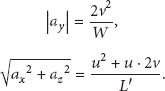

Movement of COM including the pelvis rotation (W= width of pelvis; β: pelvis rotation angle).
2.1.3. Scaled Visual Odometry
We implement the IMU-camera with kinematic walking mode to provide human walking speed and triaxis angular velocity in real metric units as shown in Figure 3. The monocular VO only can provide scale-free position and rotation estimation. In order to provide the scale factor, the human walking speed is assumed to be equal to the camera moving speed. The current scale factor can be retrieved from


The
Figure 6 shows the experiment result of the scaled Visual Odometry.
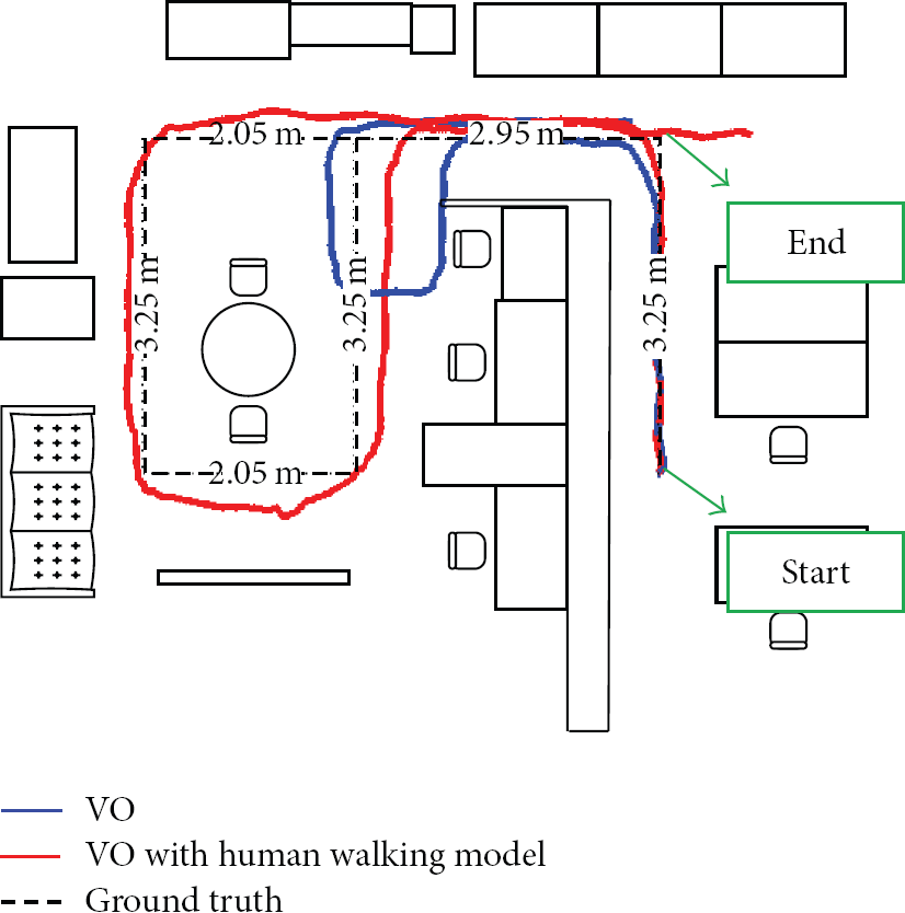
Room plan and human walking trajectory estimations.
2.2. Moving Trajectory and Anchor Location Estimation
In order to estimate the anchor node location, we fuse the scaled VO and calibrated RSSI data by using UKF. The calibrated RSSI data includes the geometric distance information from anchor node to each sensor node. To transform the RSSI data to geometric distance, we need to calibrate the transform parameters at first. The sensor fusion result can provide moving trajectory and anchor location simultaneously. Therefore we detail the calibration and sensor fusion method in this section.
2.2.1. RSSI Calibration
The distances between each node are estimated via RSSI data. The RSSI data is based on the physical fact of wireless communication and decreases with increased distances. Log distance path loss model [48] is a basic way of estimating path loss as a function of distance between the nodes. Using the initial path loss


2.2.2. Sensor Fusion
The sensor node can measure the RSSI data for computing the distances from a sensor node to the anchor nodes. Using the distance information to locate the sensor node position is a range-only problem. We use UKF to fuse the RSSI and VO trajectory result to estimate the moving path of a sensor node. We assume that the rotation and translation between the IMU-camera and RF are fixed. The state vector includes sensor node position


3. Hardware Design
We use wireless AP as our sensor node and anchor node. The difference of wireless AP between sensor node and anchor node is the signal passing procedure. Besides wireless AP, the sensor node has an IMU-camera to provide sensor data for the VO. The anchor node can broadcast the node ID so that the RSSI can be collected by the sensor node together with the node ID of an anchor node. The IMU-camera in sensor node is implemented as a wearable device for a human to estimate the walking speed and moving trajectory.
3.1. Access Point
The hardware device in Figure 7 includes a MCU (MSP430FS5438) and a RF chip (CC2500EMK). The wireless network protocol is SimpliciTI [52], which is a TI (Texas Instruments) proprietary low-power RF network protocol. The transmitting node is set to be a sensor node, and 11 fixed nodes are set to be anchor nodes. And the nodes are placed on the ground during the experiments.

Access point device.
3.2. IMU-Camera
To combine a CMOS camera and a 6-axis IMU, we design a FPGA to integrate communication and other peripherals. The FPGA code is programmed to synchronize the IMU measurement by using the camera frame sync signal. The frame rate of the camera is 64 fps and the IMU sampling rate is 640 Hz. For each frame, we can get 10 IMU samples and each IMU sample includes gyroscope and accelerometer data. Table 1 lists the types of the IMU and camera used in our experiments. The camera is calibrated through a standard procedure using MATLAB toolbox. The IMU and camera calibration method are according to the visual-inertial SLAM [30]. Our schematic of the embedded device is shown in Figure 8, and the picture of the device is shown in Figure 9. The walking distance is about 16.8 meters and the ground truth of walking speed is obtained by (16.8 m/n)·64 fps, where n is the number of moving images. Data is acquired in real-time, real environment, and processed offline.
The specifications of the camera and IMU.


The schematic diagram of the embedded device developed.

The embedded device developed in this work and mounting position.
4. Experiment Environment
Our experiment includes real VO estimation results and virtual WSN RSSI measurement which include bias and noise effects. The VO results fuse the IMU-camera measurement data and human walking model. According to the RSSI measuring frequency, we downsample the estimated real VO routing path. Each sampling point has a real VO estimated position and virtual anchor node RSSI measurement. We analyze three methods: (1) IMU with UKF sensor data fusion method, (2) IMU-camera with human walking speed estimation, and (3) IMU-camera with human walking speed estimation and UKF sensor data fusion method, to estimate routing path for reversely locating anchor nodes in WSN. The UKF fuses the RSSI measurement and moving trajectory which includes human walking speed estimation. The experiment results show the accuracy of the reversely locating anchor nodes in RSSI bias and noise effects.
4.1. Configuration
We set the simulation area 8 m × 5.5 m. The anchor nodes are placed in the lowest density, which ensures each measurement involves three anchors coverage. Since the RSSI data fluctuated seriously over 5 meters, we assume the maximum transmitting range of the wireless signal is 5 meters. Due to the transmitting range, we deployed 11 anchor nodes in the area and the distance between each anchor node is 3.75 meters. If the other wireless networking technologies are substituted in, such as Bluetooth or ZigBee, the transmitting range can be set to 10 meters or longer and the less anchor nodes can be used in the same area. In the simulation, the anchor nodes and training nodes are assumed to be placed in two parallel planes: anchor nodes are placed at the ceiling, and training nodes and sensor nodes are hung in front of the chest of users. The height between the ceiling and the chest of users is assumed to be 1.5 meters (all users are at the same height).
4.2. Node Inconsistency
To make our experiment closer to a real situation, we introduce bias and noise of RSSI measurement into our experiments. A Gaussian random variable 
5. Experiment Results
We analyze the accuracy of the reversely locating anchor nodes in different conditions by using different moving trajectory estimation methods. Our experiment results include three different moving trajectory estimation methods based on VO as listed in Table 2. The first moving trajectory estimation method, Exp#1, is VO with UKF method. This method is commonly used in inertial navigation system. The second method, Exp#2, is VO with human walking speed estimation. The walking speed estimation can provide accuracy real scale for VO. The third method, Exp#3, is the VO with human walking speed estimation and UKF sensor data fusion method. The filter based methods in the Exp#1 and Exp#3 do not use Trilateration method but update state parameters recursively in finding the anchor node locations. We also consider the bias and noise effect of RSSI to the anchor node location accuracy. The average error, maximum error, and standard deviation are listed in the error analysis table. The bold font in the table means the minimal value in these three methods.
Experiment methods.

5.1. RSSI Bias Effect
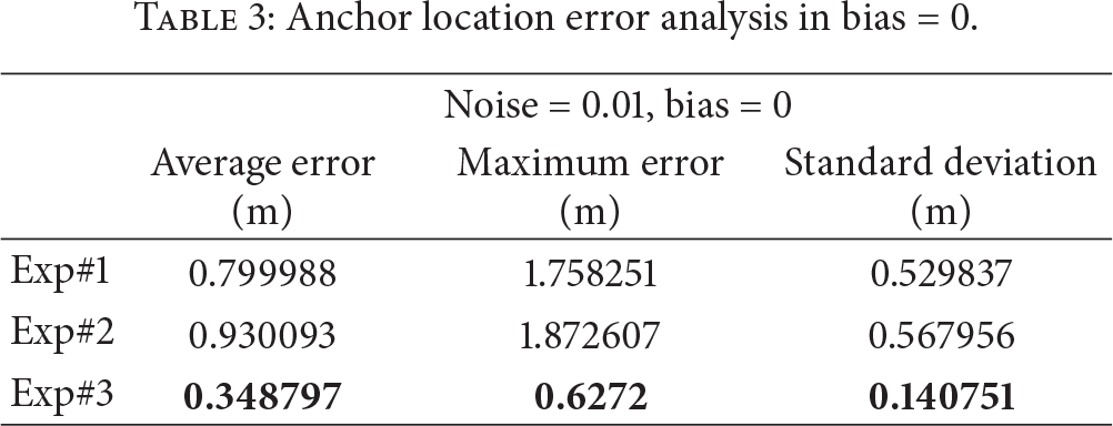
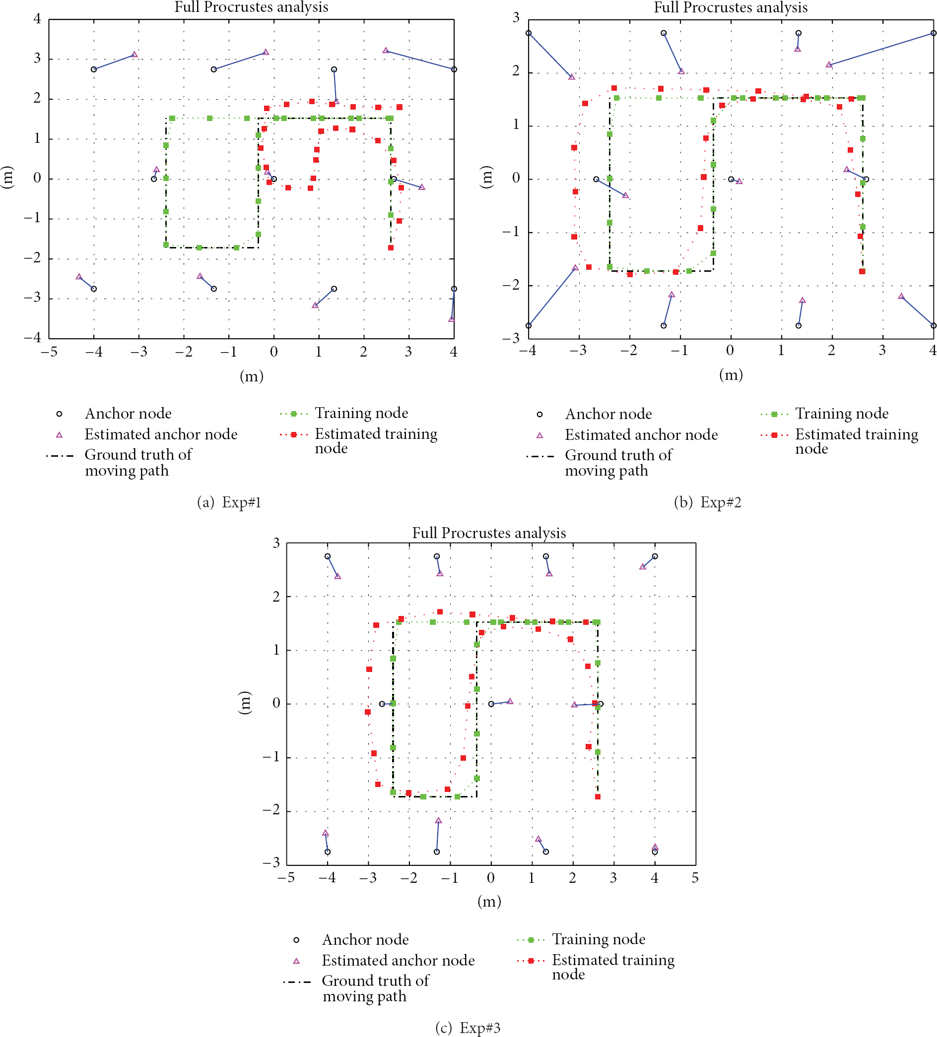
We set the mean of the noise probability density function (PDF) to 0 and 0.5, and the noise is 0.01. The RSSI biases in Figures 10 and 11 are 0 and 0.5. The RSSI data collection frequency is two times per second. The red line is the moving trajectory estimation result and the green line is the ground truth of the trajectory. The black circle is the real location of an anchor node, and the pink triangle is the estimated anchor node location. The black dotted line is the ground truth of the moving trajectory. In Figure 10(a), the Exp#1 has the scale error which comes from the IMU data process. The trajectory estimation error and RSSI measurement error are directly influencing the accuracy of the anchor node location. Therefore the estimations of moving trajectory and anchor location are far from the ground truth. We introduce the Exp#2 method and the estimation result in Figure 10(b). The moving trajectory estimation of Exp#2 is not affected by the RSSI bias, because the trajectory estimation does not include the RSSI data. However the RSSI bias still affects the anchor location estimation results due to the Trilateration method. In contrast, the proposed Exp#3 uses UKF based loosely coupled method to fuse the scaled VO and RSSI measurement data in Figure 10(c). We use the observation error covariance of UKF to adjust the RSSI measurement error influence on moving trajectory estimation results. Tables 3 and 4 show the anchor location error comparison between Figures 10 and 11. We can find that the Exp#3 has lower estimation error than the other methods whatever the average error, maximum error, and standard deviation test results are. Between Exp#1 and Exp#3, the improvements of average error rate are 56% and 32% in Tables 3 and 4. Between Exp#2 and Exp#3, the average error improvements are 62% and 52% in Tables 3 and 4.
Anchor location error analysis in bias = 0.
Anchor location error analysis in bias = 0.5.


Bias effect to the trajectory and anchor locations estimation (noise = 0.01 m, bias = 0 m).

Bias effect to the trajectory and anchor locations estimation (noise = 0.01 m, bias = 0.5 m).
5.2. RSSI Noise Effect
The noise effects to our experiment results are shown in Figures 12 and 13. The noise variances in Figures 12 and 13 are 0.01 m and 0.03 m, and the RSSI bias is 0.2. The inaccurate scale estimation in Figures 12(a) and 13(a) causes the moving trajectory and anchor location estimation error. The accuracy of the moving trajectory has influence on the reversely anchor locations. In Figures 12(b) and 13(b), although the RSSI noise does not influence the moving path estimation, the error still influences the reversely anchor node locations estimation in Trilateration method. We can find that the noise has great effect to the Trilateration methods though the trajectory estimation is close to the ground truth than Exp#1. In contrast, the Exp#3 can tolerate the noise, because the UKF has the error model to overcome the noise of RSSI as shown in Figures 12(c) and 13(c). Tables 5 and 6 show the anchor node location error estimation comparison between Figures 12 and 13. The Exp#3 still has the lowest estimation error on moving trajectory and anchor locations. The improvement rates of average error are 48% and 33% between Exp#1 and Exp#3 in Tables 5 and 6. Between Exp#2 and Exp#3, the improvement rates of average error are 54% and 60% in Tables 5 and 6. According to the above analyses, the UKF based loosely coupled approach can reduce the measurement errors. We find that the Exp#3 can provide better performance than Exp#1 and Exp#2 when RSSI bias and noise change.
Anchor location error analysis of noise = 0.01.

Anchor location error analysis of noise = 0.03.

Noise effect to the trajectory and anchor locations estimation (noise = 0.01 m, bias = 0.2 m).

Noise effect to the trajectory and anchor locations estimation (noise = 0.03 m, bias = 0.2 m).
6. Conclusion
We propose a reversely anchor node location method by using UKF to fuse the RSSI data and attitude of monocular VO with real scale. The scale factor of monocular VO relies on a kinematic walking model to estimate the walking speed. Instead of double integration of acceleration, the scale factor from the walking speed estimation uses only the acceleration information of the body. The loosely coupled approach fuses the RSSI data and attitude of VO to provide an accurate motion trajectory and anchor node locations simultaneously. We test our VO algorithm in real environment and add reasonable bias and noise to RSSI data in our WSN simulation environment. The experiments show that inaccurate scale estimation of Exp#1 influences the estimation of the anchor locations. The Exp#2 uses IMU-camera with human walking speed estimation method to perform scaled VO algorithm. The moving trajectory is close to the ground truth than Exp#1. Note that the RSSI measurement noise and bias does not affect the path estimation; it only affects the location accuracy of anchor nodes when using Trilateration method. The best estimation method of the moving trajectory and anchor locations is Exp#3 which is scaled VO with UKF based loosely coupled method. The Exp#3 can endure the bias and noise effect of RSSI because of the noise model in UKF and has better performance and measurement error tolerance than the other methods. The experiment results show that the proposed method, Exp#3, has lower estimation error when locating anchors. The error of locating anchors can be improved around 30%~60%.
Footnotes
Conflict of Interests
The authors declare that there is no conflict of interests regarding the publication of this paper.