
Abstract
The carbon nanotube (CNT) reinforced functionally graded materials (FGM) are expected to be the new generation materials having wide range of unexplored potential applications in various technological areas such as aerospace and structural and chemical industry. The present work deals with the finite element modeling and free vibration analysis of CNT based functionally graded beam using three-dimensional Timoshenko beam theory. It has been assumed that the material properties of CNT based FG beam vary only along the thickness and these properties are evaluated by rule of mixture. The extended Hamilton principle has been applied to find out the governing equations of CNT based FG beam. Finite element method is used to solve governing equation with the exact shape functions. Initial analysis deals with CNTs assumed to be oriented along the length direction only. But practically it is not possible. So, further work deals with the free vibration analysis of functionally graded nanocomposite beams reinforced by randomly oriented straight single walled carbon nanotubes (SWCNTs). The Eshelby-Mori-Tanaka approach based on an equivalent fiber is used to investigate the material properties of the beam. Results are presented in tabular and graphical forms to show the effects of carbon nanotube orientations, slenderness ratios, and boundary conditions on the dynamic behavior of the beam.
1. Introduction
Functionally graded material (FGM) belongs to a class of advanced material characterized by variation in properties as the dimension varies. FGM was invented with the prime requirement of thermal stability at high temperatures along with better mechanical properties. FGM concept was originated in Japan in 1984 during the space plane project.
Metallic part of FGM will take care of better mechanical properties and ceramic part will take care of thermal stability at high temperatures. The overall properties of FGM are unique and different from any of the individual materials that form it. Due to these advantages FGM has a wide range of applications such as in
aerospace to make space plane bodies, components of the rocket engines,
medicine to replace the living tissues like bones and teeth,
defense as a penetration resistant material for bullet proof vests as well as armor plates,
energy as thermal barrier, protective blade in gas turbine,
optoelectronics as graded refractive index material,
other applications consist of automobile engine component and nuclear reactor components, and so forth.
These applications explicitly require good thermal properties. So, it is important that analysis of thermal behavior of FGM should be carried out which has initiated the work related to this area. Lot of researchers have presented their work so far.
CNTs are known to be discovered by Iijima in 1991. CNT exhibits extraordinary mechanical properties: the Young's modulus is over 1 Tpa. The estimated tensile strength is 200 GPa. It is due to carbon-carbon sp2 bonding. These properties are ideal for reinforced composites, nanoelectromechanical systems (NEMS). Carbon nanotubes (CNTs) are also known for their good mechanical and electrical properties. Thus the use of CNT with functionally graded material (FGM) provides definitely improved mechanical, electrical, and thermal properties. Important advantages of CNT based on FGM are listed below:
higher strength to density ratio,
higher stiffness to density ratio,
better fatigue and wear resistance,
better elevated temperature properties (higher strength-lower creep rate),
ability to fabricate directional mechanical properties,
provide multifunctionality,
provide ability to control the deformation, dynamic response of the system, wear and corrosion of parts, and so forth,
provide ability to remove stress concentrations,
provide opportunities to take the benefits of different material systems.
The key of using CNT based on FGM is that one can obtain these properties as per the requirement just by varying the distribution and composition of CNT. That is how one can get directional properties and can control other parameters. Another advantage stated above is the stress concentration free material. It is because the cross section shows that there are no layers inside the material and instead there is a continuous gradation of materials from top to bottom. So, there is no stress concentration and delamination of layers. As it can be manufactured from CNT, polymers, and ceramics, one can take the advantages of each constituent material.
CNT is a new form of carbon, configurationally equivalent to 2D graphene sheet rolled into a tubular form. It is grown by several techniques in the laboratory which is just a few nanometers in diameter and several microns in length. Main problems facing the manufacturers are difficulty in homogeneous dispersion of CNT into the matrix material which results in low interfacial bond strength between these constituents and it affects the quality of the product. There is also a problem of mass production with low cost. To overcome these problems up to certain extent, there are different techniques to manufacture the CNT based on FGM. Most common method is powder metallurgy. Besides this, there are also many methods such as melting and solidification, thermal spray including plasma and cold spraying, electrochemical deposition, vapor deposition, and nanoscale dispersion. The CNT based on functionally graded materials are used in wind turbines, tissue engineering, thin films of shape memory alloys, nanoelectromechanical systems such as micro sensors used in robotics, micro actuators, telecommunications, and transport industry.
All the work that has been carried out up till is presented here regarding the properties of FGM, vibration analysis of a nanocomposed functionally graded material shaft using finite element modeling. So, majorly, it deals with material sciences, rotor dynamics, FEM, and theory of vibrations. The history of this research consists of 2 parts as discussed above, that is, finding out material properties and vibration analysis.
In field properties of FGM metals are good conductors of heat and ceramics acts as good insulators. So, they are used individually according to the requirement, but there are certain areas where both are needed simultaneously. In these applications metals and ceramics are bonded directly. At elevated temperatures it is found that thermal stresses are produced which is responsible for debonding of metal and ceramics as well; the delimitation in ceramics takes place. To avoid this, scientist Kawasaki and Watanabe proposed graded interlayer concept for metals and ceramics. Such material possesses super heat resistant property and sufficient toughness which also reduces the thermal stresses at elevated temperatures. This concept is known as functionally graded material (FGM) [1]. So, one can say FGM is a material in which mass and weight proportion is varied along the cross section. Generally, ceramics have high percentage than metals on the outside so that it can be used at elevated temperatures. The concept of FGM is discovered after the concept of composite materials. In case of composite materials the metal fiber is surrounded by the matrix, which gives high specific strength and stiffness with minimum specific density. In materials science “functionally graded material (FGM)” may be characterized by the variation in composition and structure gradually over volume resulting in corresponding changes in the properties of the material. The materials can be designed according to specific function and applications. Various approaches based on the bulk (particulate processing) perform processing layer processing and melt processing are used to fabricate the functionally graded materials. The basic unit for FGM representation is maxel; the term maxel was introduced in 2005 by Rajeev Dwivedi and Radovan Kovacevic at Research Centre for Advanced Manufacturing (RCAM); the attributes of maxel include the location and volume fraction of individual material components.
An overview of FGM was taken by Mahamood et al. [2]. The fabrication processes, area of application, some recent research studies, and the most promising FGM fabrication method (solid freeform SFF) were presented by them. The processing technique of FGM consists of vapour deposition, powder metallurgy, centrifugal, and SFF. For future research, SFF method needs modification through extensive characterization so that the cost of FGM will be reduced and reliability will be increased. Durodola and Attia [3] focused mainly on FGM materials for rotating hollow and solid disks. In their paper, FGM was considered as a nonhomogeneous orthotropic material. The property variation is considered as exponential. The hoop stresses and radial stresses were calculated after finding out Young's modulus for FGM layer wise which vary along the radial direction only. Different values were obtained for different values of exponent. Aboudi et al. [4] considered the higher order micromechanical theory. It was more advantageous than micromechanics approach which was based on representative volume element. RVE do not deal with continuously changing properties due to nonuniform inclusion spacing. In their paper they considered only unidirectional grading of properties. It was applied for thermal and mechanical fields in FGM. Giunta et al. [5] considered the distribution of material properties according to power law in terms of the volume fraction of the material constituents. The properties such as Young's modulus, Poisson's ratio, and density vary along 1 direction and two perpendicular directions together or independently.
In field vibration analysis of CNT based on FGM the later inventions in the field of material science have proved that CNT with functionally graded material (FGM) provides improved mechanical, electrical, and thermal properties. Andrews et al. [6] fabricated the multiwalled carbon nanotube/polymer composites by shear mixing. Results showed that as concentration of nanotubes increases both strength and stiffness increase. Yas and Heshmati [7] worked on dynamics of functionally graded nanocomposite beams with randomly oriented single-walled carbon nanotubes. They found that under the action of moving load, CNT-FGM beam with symmetrical distribution gives superior properties than that of unsymmetrical distribution. Alshorbagy et al. [8] presented the dynamic characteristics of functionally graded beam with gradation of material axially or transversally through the thickness based on the power law. They converted geometrically nonuniform beam into axially or transversely uniform geometrical beam. The work carried out by Ke et al. [9] gave the information about the nonlinear free vibration of functionally graded nanocomposite beams with single-walled carbon nanotubes (SWCNTs). It was based on Timoshenko beam theory and von Karman geometric nonlinearity. They also considered the gradation of material properties in thickness direction only. Khosrozadeh and Hajabasi [10] worked on free vibration of embedded double-walled carbon nanotubes considering nonlinear interlayer van der Waals forces. It was based on Euler-Bernoulli theory. The variation of the interlayer distance along the circumference of DWCNTs causes the inner and outer tubes deflections which were modeled as the interlayer van der Waal force. Natsuki et al. [11] also worked on double-walled carbon nanotubes. Ray and Batra [12] demonstrated the active control of smart structures using single-walled carbon nanotube reinforced 1–3 piezoelectric composite. Micromechanical analysis was carried out to find out the values of effective piezoelectric moduli. Some more about the nonlinear dynamic response of nanotube-reinforced composite plates was carried out by Wang and shen [13]. The material properties were considered as function of temperature. The higher order shear deformation theory was considered along with von Karman type kinematic nonlinearity to find the equation of motion. Work carried out up till was not restricted to only vibration analysis; the vibration control was also included. For safe and efficient functioning of all rotating machines, reduction of rotor vibration is very important. Das et al. [14] worked on the vibration control and stability of the system using electromagnetic exciters. They provided suitable force of actuation which was obtained by varying the control current. The rotor shaft was modeled according to Rayleigh beam theory with viscous damping. To visualise the effect of damping, the unbalance response was plotted for controlled and uncontrolled situations. The active vibration control using fuzzy logic controllers was demonstrated by Hossain Nezhad Shiraji et al. [15]. They worked on both PID controller and FLC to dampen the plate vibration. For the fuzzy inputs and outputs the designed FLC used 5 membership functions. The other method of vibration analysis is modal analysis which was given by Kim and Lee [16]. The natural characteristics of the system such as frequency, damping, and mode shapes were used to describe a structure. The modal parameters may be determined by FEA or other such methods. Mostly modal analysis is used in dynamic problem, vibration, or acoustics.
Regarding the above-mentioned histories, it seems that there is a need for proposing a method for vibration analysis of randomly orientation CNT based on FG materials is introduced. Results are presented in tabular and graphical forms to show the effects of carbon nanotube orientations, slenderness ratios, and boundary conditions on the dynamic behavior of the beam. So the objectives of the present work are as stated below:
finding out the material properties of CNT based on FGM,
free vibration analysis of Timoshenko beam,
finding out the effect of CNT orientation.
2. Modelling of Beam
2.1. Calculation of Mechanical Properties of Beam
The modeling of beam starts with the calculation of material properties. As CNT volume is assumed to vary along the thickness only, material properties for each layer are calculated first and finally effective values for the entire beam are calculated. Here, linear variation of volume fraction of CNT (Vcnt) is considered. It is calculated by following formula:

Here Vcnt* depends on mass fraction and density of CNT and density of matrix and it is given by
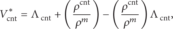
where Λcnt called as is mass fraction of CNT. For uniform CNT distribution Vcnt equals the Vcnt*. After calculating volume fraction Young' modulus, shear modulus, Poisson's ratio, and density of a beam can be calculated as follows:
where Ecnt and Gcnt are Young's modulus in longitudinal, transverse direction and shear modulus for carbon nanotube. E m , G m are Young's modulus & shear modulus for matrix (ceramic). η j (j = 1,2, 3) is CNT efficiency parameter.
2.2. Problem Formulation
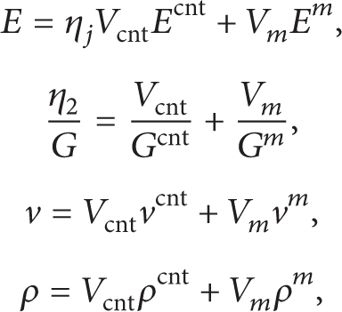
Here first order shear deformation theory is considered for Timoshenko beam. The axial and transverse displacements for this beam are as follows,
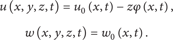
In this case three degrees of freedom per node have been considered. They are longitudinal displacement, transverse displacement (along Z axis), and angular rotation about Y-axis. This is shown in Figure 1.
Degree of freedom for single element.
Strain-displacement relation for small displacement can be derived from (4) as follows:

From above equation, the constitutive relations can be formed for longitudinal and shear stresses as follows:
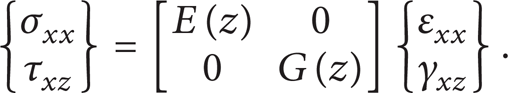
Constitutive relations are formed to calculate strain energy and kinetic energy of beam. For given case the final expressions for these energies are as follows:

where the symbol

Using (7) in above equation, the governing equations can be

The values of stiffness coefficients and mass moments from (5) are given below. K s is shear correction factor

2.3. Finite Element Analysis
To solve the above governing equation finite element analysis is implemented. Finite element analysis aim is to find out the field variables (displacement) at nodal points by approximate analysis. These field variables are related to the field variables of nodal points inside the element. Here employing the approximate solution method the governing equations are approximated by a system of ordinary differential equations. The solution of the above partial differential equations is assumed in the following form:
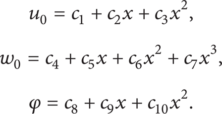
In the above equations, the order of interpolation of slope is less than that of order of transverse displacement. This is to avoid the shear locking of the element. Some constants from above equation can be defined as

where

So, the longitudinal, transverse displacement and angular rotation in terms of field variables can be written as
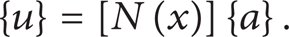
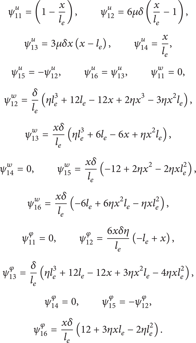
In the above equation [N(x)] is matrix having functions of x and {a} is vector of independent constants. Applying the boundary conditions at nodes 1 and 2, respectively, depending upon the end supports, shape functions for each case can be obtained as follows:

Here,

The ψ(x) represents matrix of exact shape functions. For this case, ψ u (x), ψ w (x), and ψϕ(x) give the exact shape functions for axial displacement, transverse displacement, and angular rotation, respectively. The values of these shape functions are given below:
Finally, the equation of motion is derived as follows:

where [M] denotes the global mass matrix and [K] denotes the global stiffness matrix. Initially, elemental stiffness and mass matrices need to find out.
3. Alidation of Present Theory
The elemental stiffness matrix can be obtained as given

In this equation [B] is strain displacement matrix and [D] is constitutive matrix. Integrating the above equation the elemental stiffness matrix can be obtained. The stiffness matrix is symmetric, so the terms in upper triangular matrix are given below and the remaining terms are zero:

Similarly, elemental stiffness matrix can be obtained by using following formula:

Based upon the present theory a Matlab code has been developed and implemented to a beam with h = 0.1 m, L/h = 10 to study the convergence of nondimensional fundamental frequency for Vcnt* = 0.12. It is calculated by the following formula:

The material properties of the beam are as given in Table 1.
Material properties of beam.
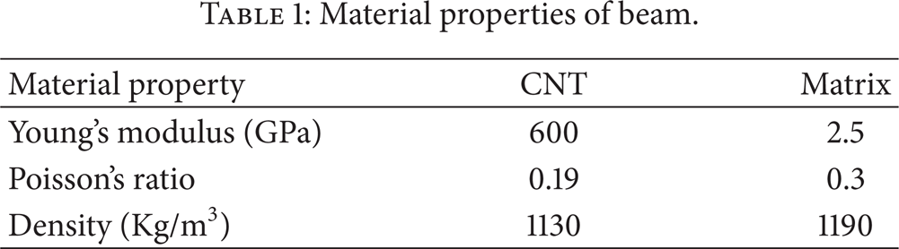
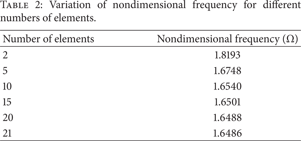
Table 2 shows the nondimensional frequency for different numbers of elements.
Variation of nondimensional frequency for different numbers of elements.
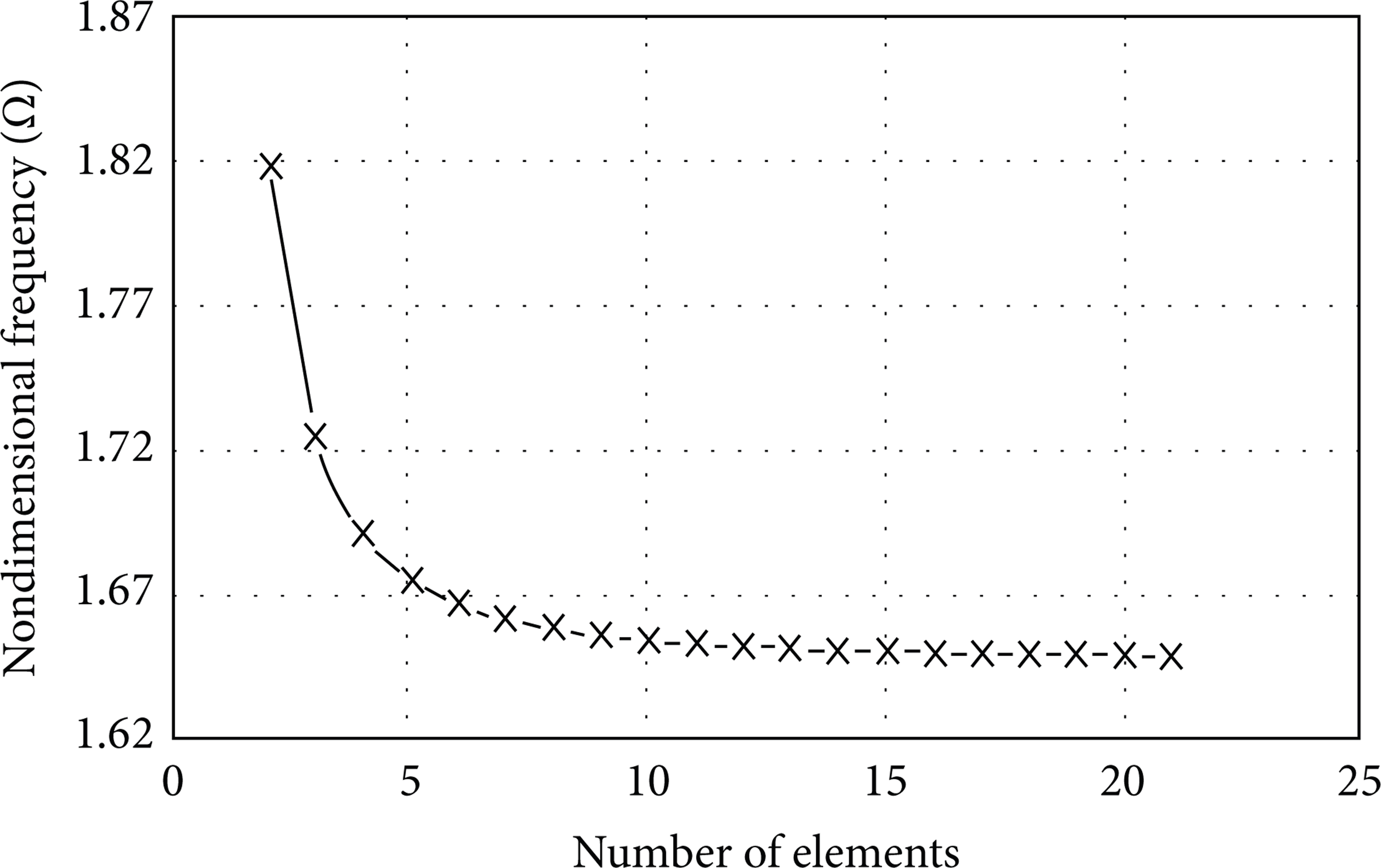
The graph is plotted between number of elements along X-axis and nondimensional frequency along Y-axis.
From the Table 2 and Figure 2 it is found that the result converges for 21 numbers of elements. So, for further analysis 21 elements were used. Now, present theory is validated for Vcnt* = 0.12, 0.17, and 0.28. Results are obtained with both ends of the beam clamped and it is compared with the results given by Ke at al. [9]. Table 3 compares present nondimensional fundamental frequencies with the results available in the literature. From the table it is found that the results agree well with reference.
Comparison of nondimensional fundamental frequencies.

Convergence study.
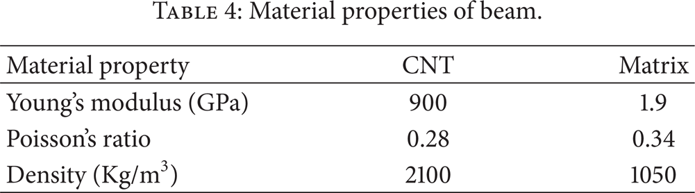
Proposed theory is also validated by comparing static deflection of free end of cantilever beam with that presented by Rokni et al. [17] (Table 5). The beam dimensions are L = 0.14 m, b = 0.02 m, and h = 0.01 m. For this case the assumed material properties are given in Table 4.
Material properties of beam.
Comparison of results for cantilever beam.

The deflection at the free end of the beam is calculated by following formula:

4. Results
Now, the results are obtained for above beam with simply supported end conditions for varying volume fraction of CNT. The effect of variation of volume fraction of CNT on nondimensional fundamental frequency is shown in Table 6 for slenderness ratio that is equal to 10 in all cases.
Effect of variation of volume fraction of CNT on nondimensional fundamental frequency.
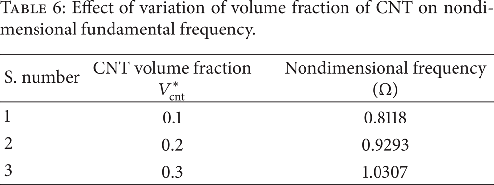
From Table 6 it is found that nondimensional frequency increases as volume fraction of CNT increases. Now, the results are obtained to observe the effect of slenderness ratio on dimensional frequency for constant CNT volume fraction. Table 7 shows effect of slenderness ratio (L/h) on nondimensional fundamental frequency with Vcnt = 0.1. It shows that as L/h ratio increases frequency also increases.
Effect of slenderness ratio on nondimensional fundamental frequency.

Finally, mode shapes are plotted for first case of Table 7. First five modes are shown in Figure 3. Mode shapes are the vibration patterns for the particular frequency and they are obtained from eigenvectors.

Five modes shapes corresponding to the first five natural frequencies.
Now, the dynamic analysis is carried out for given beam. Displacement versus time diagram is plotted to understand the time response with varying CNT volume fraction. For simply supported case, the maximum displacement obtained for Vcnt = 0.1, 0.2, and 0.3 are 0.029 m, 0.022 m, and 0.016 m, respectively. Figure 4 shows the response of sinusoidal force of magnitude 100sin (80t) for the same case of mode shapes for 0.45 seconds in the tip of beam. As Figure 4 shows, if Vcnt increases, maximum displacement decreases.
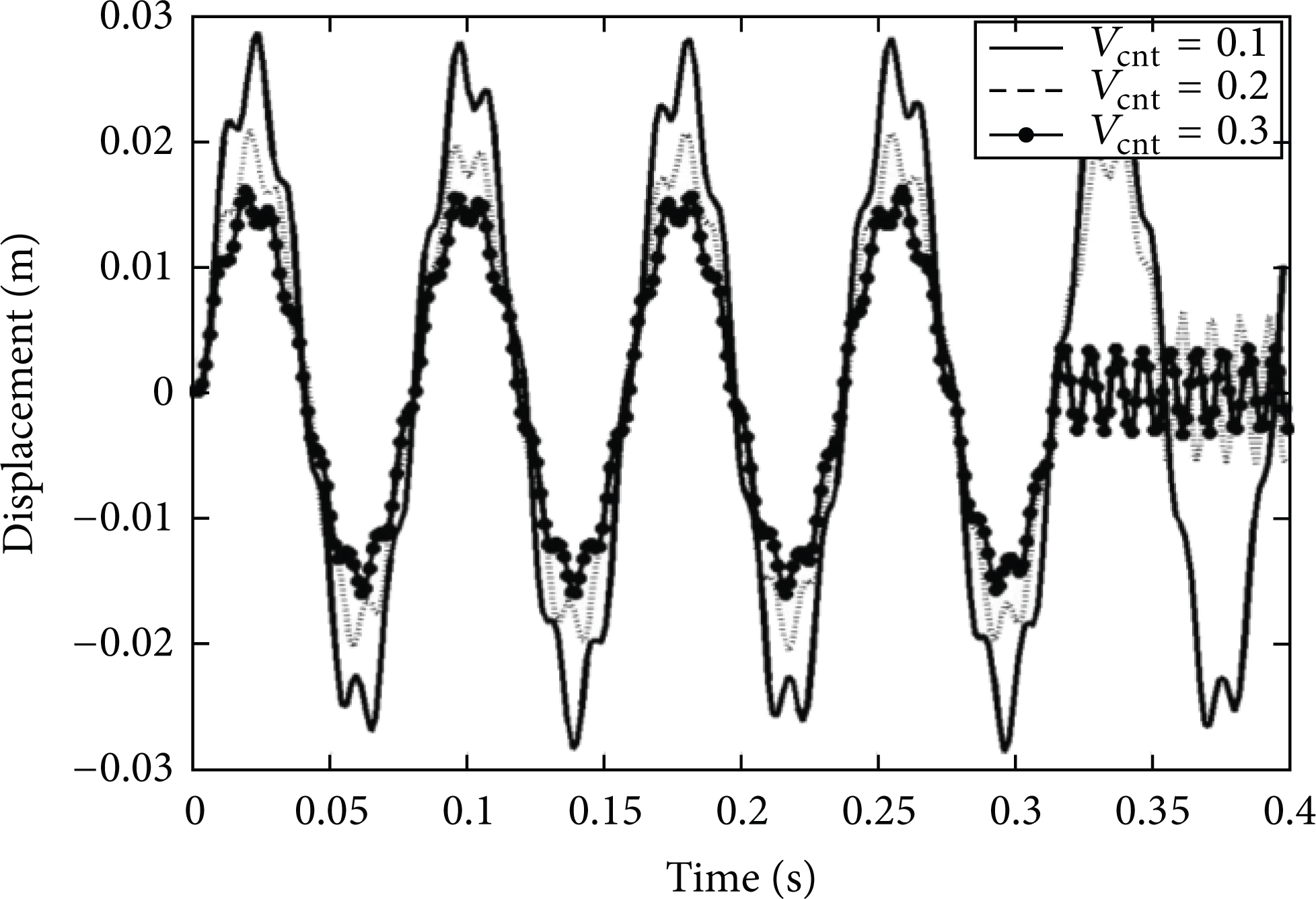
Displacement versus time graph for Vcnt = 0.1, 0.2, and 0.3.
5. Effect of Carbon Nanotube Orientation
In the previous analysis the CNTs are assumed to be unidirectional along the length. But practically, it is not possible. The effect of CNT orientation on natural frequency is discussed in this section.
5.1. Material Properties of FG-CNTRC (Carbon Nanotube Reinforced Composite)
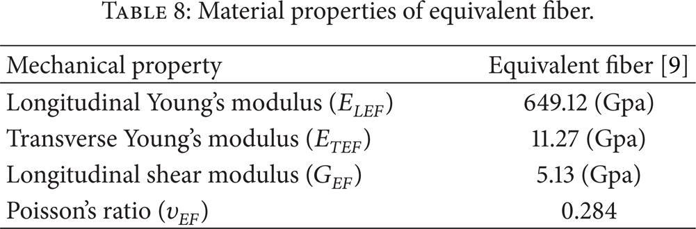
An embedded carbon nanotube in a polymer matrix is considered to be replaced with an equivalent long fiber for predicting the mechanical properties of the carbon nanotube/polymer composite. The inverse rule of mixture is used for calculating material properties of equivalent fiber [7]:

where E, G, ν, and V are the longitudinal Young's modulus, shear modulus, Poisson's ratio, and volume fraction, respectively. Suffixes EF, C, and m show properties for equivalent fiber, CNT, and matrix material, respectively. The equivalent fiber for SWCNT with chiral index of (10, 10) is a solid cylinder with diameter of 1.424 nm. Material properties for this CNT taken from reference are mentioned in Table 8.
Material properties of equivalent fiber.
5.2. Modelling of Beam
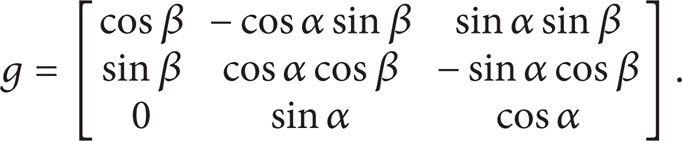
The effect of randomly oriented, straight CNTs is formulated here. The orientation of a straight CNT is characterized by two Euler angles α and β, as shown in Figure 5. Thus giving rise to the base vectors

where g is given by
The orientation distribution of CNTs in a composite is characterized by a probability density function p(α, β) satisfying the normalizing condition:

Consider CNTs to be completely randomly oriented, the density function for this case is

The Hill's elastic module of the reinforcing phase can be calculated from the equality of following two matrices [7]:
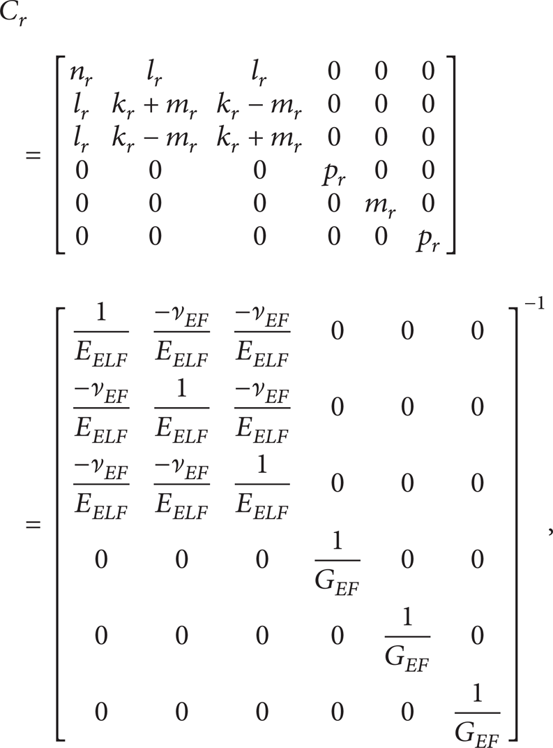
where C r is the stiffness tensor of the equivalent fibers and when CNTs are assumed randomly oriented in the matrix, the composite is assumed to be isotropic then bulk modulus K and shear modulus G of the beam are derived as:

Finally, Young's modulus for oriented CNT considering modified shear and bulk modulus will be

Keeping all other values constant and using Young's modulus from the above equation, (7), (9), and (24) are modified to obtain the effect of CNT orientation on elemental stiffness and mass matrices.
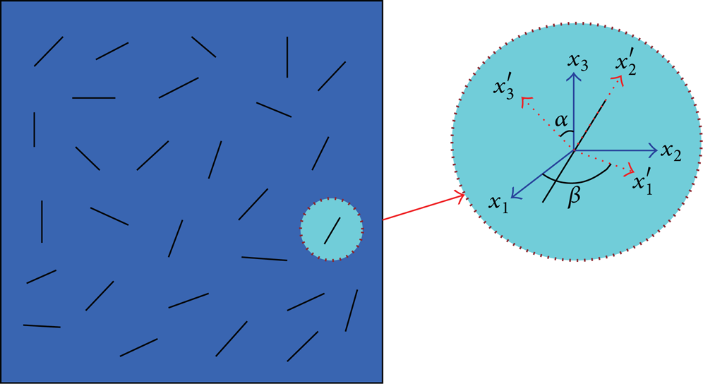
Representative volume element (RVE) with randomly oriented, straight CNTs [7].
As CNT volume is assumed to vary along the thickness only, material properties for each layer are calculated first and finally effective values for entire beam are calculated. Here, linear variation of volume fraction of symmetrical CNT Vcnt is considered. It is calculated by following formula:

5.3. Numerical Results
This theory has been implemented to a beam with h = 1 m, L/h = 20 to study the convergence of nondimensional fundamental frequency for Vcnt* = 0.075. It is calculated by following formula:

Now, the material properties assumed for the beam are as mentioned in the Table 9.
Material properties of beam.

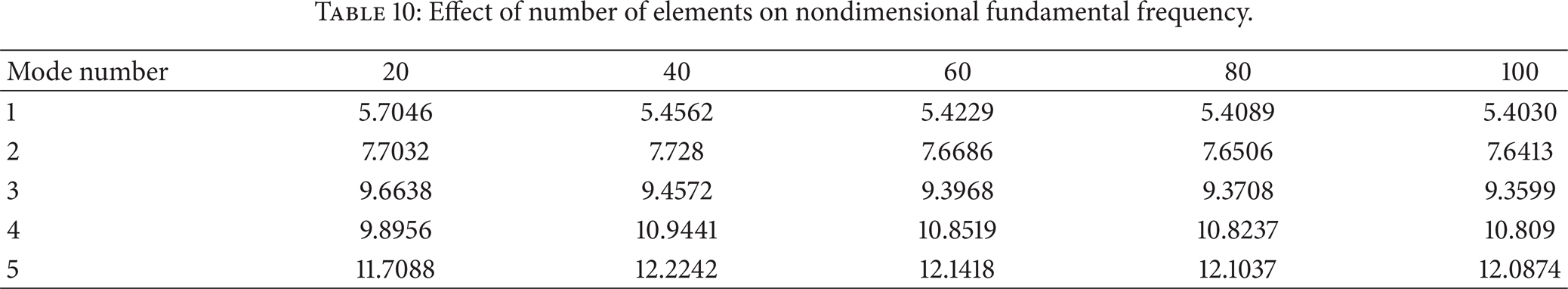
With these properties and applying the present theory, results of the first five nondimensional frequencies for clamped-clamped (C-C) are obtained. The effect on SFG-CNTR beam based on Timoshenko beam theory with different number of elements is obtained to study the convergence and is shown in Table 10. The Graph is also plotted to observe the convergence of frequencies as shown in Figure 6.
Effect of number of elements on nondimensional fundamental frequency.
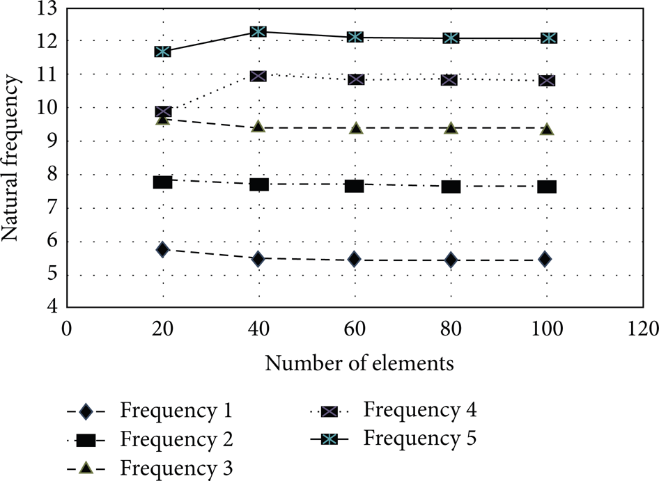
Convergence study of frequencies with consideration of CNT orientation.
It is observed from Figure 6 and Table 10 that the convergence of the present results occurs with a number of elements N = 100.
To validate the results beam slenderness ratio L/h = 20 and Vcnt* = 0.075 are selected with clamped-clamped condition of Timoshenko beam and are verified with the results given by Yas and Heshmati [7].
Table 11 compares the effect of variation of volume fraction of CNT on dimensionless fundamental frequency. The first five frequencies for clamped-clamped, SFG-CNTRC (carbon nanotube reinforced composite) beams are shown in the table.
Effect of variation of volume fraction of CNT on nondimensional fundamental frequency.
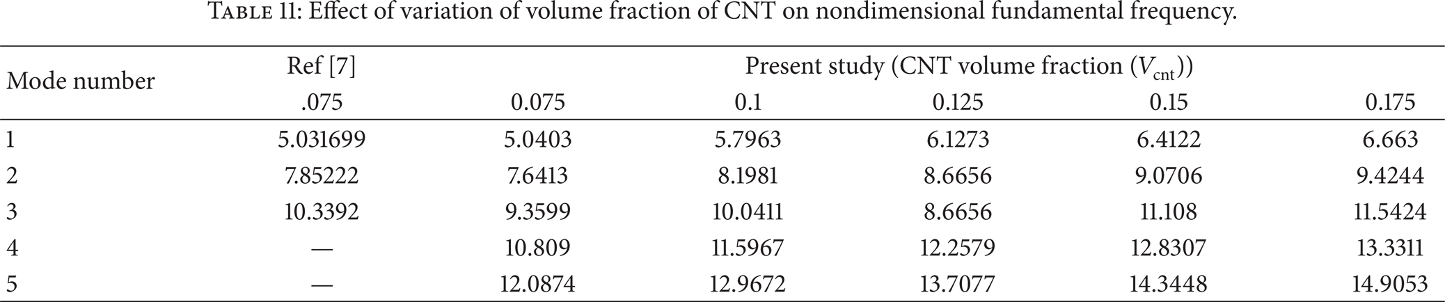
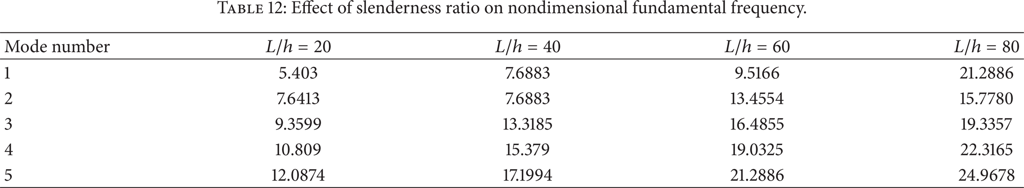
From this table it is clear that the values of natural frequencies increase due to the effect of CNT orientation. Table 12 shows the effect of slenderness ratio (L/h) on nondimensional fundamental frequency. Frequencies are calculated for slenderness ratios 20, 40, 60, and 80. It is found that as L/h ratio increases frequency also increases.
Effect of slenderness ratio on nondimensional fundamental frequency.
Displacement versus time diagram is plotted to understand the time response with varying CNT volume fraction. Figure 7 shows the response of sinusoidal force of magnitude 100 N which is acting at the centre of the beam with clamped-clamped boundary condition of FG beam and exciting frequency of 80 Hz. The maximum displacement in this case is found to be 0.09 micrometers.

Plot of displacement versus time of CNT based on FG beam under sinusoidal loading.
6. Conclusions
In the present work, CNT based on FG Timoshenko beam has been modeled using finite element method. Firstly convergence of results has been studied and then different analyses such as static and dynamic analyses have been carried out. Nondimensional fundamental frequencies are calculated for different volume fractions of CNT and slenderness ratio. Mode shapes and displacement diagrams are also plotted for this beam. From this analysis it can be concluded that
as volume fraction of CNT increases, fundamental frequency also increases. The reason behind this is more volume of CNT provides more stiffness to the beam which results in higher frequencies.
Nondimensional fundamental frequency increases as slenderness ratio increases.
The response of displacement versus time shows that for increasing values of volume fraction displacement reduces.
Conflict of Interests
The authors declare that there is no conflict of interests regarding the publication of this paper.