
Abstract
The thermohydraulic performance in a tube containing a modified twisted tape with alternate-axes and wing arrangements is reported. This work aims to investigate the effects of wing arrangements (opposite (O) and parallel (P) wings) at different wing shapes (triangle (Tri), rectangular (Rec), and trapezoidal (Tra) wings) and on the thermohydraulic performance characteristics. The obtained results show that wing twisted tapes with all wing shape arrangements (O-Tri/O-Rec/O-Tra/P-Tri/P-Rec/P-Tra) give superior thermohydraulic performance and heat transfer rate to the typical twisted tape. In addition, the tapes with opposite wing arrangement of O-Tra, O-Rec, and O-Tri give superior thermohydraulic performances to those with parallel wing arrangement of P-Tra, P-Rec, and P-Tri around 2.7%, 3.5%, and 3.2%, respectively.
1. Introduction
In recent years, heat transfer enhancement (heating/cooling) in heat exchangers has been intensively investigated in order to optimize the condition and configuration of heat transfer system. Passive heat transfer augmentation techniques are manners to increase heat transfer coefficient without an external power. Tube inserts form an important group of the enhancement techniques. Among the inserts, twisted tapes have gained great attention due to their low cost and acceptable performance. Numerous research works have aimed to obtain a good tradeoff between a benefit (a heat transfer improvement) and a drawback (a pressure drop increase) of utilizing twisted tapes. The attempts were made by the modifications of twisted tape geometries. Some modifications of the twisted tapes were conducted principally to suppress an increase of pressure drop in tubes; the modified twisted tapes in this group include the loose-fit twisted tape [1, 2], regularly spaced tape element [3, 4], short-length twisted tape [5], twisted tape with spacer at the trailing edge [6], and wing twisted tapes [7]. However, heat transfer rates and thermohydraulic performances associated with the modified twisted tapes mentioned above were significantly decreased compared to those given by a typical twisted tape. On the other hand, some twisted tapes were modified with a major purpose to enhance heat transfer rates by improving fluid mixing between the tube core and inner tube wall [8–17]. Recently, numerous modified twisted tapes with different geometrics for heat transfer enhancement have been proposed [18–26] such as multiple short-length twisted tape [18], rectangular-cut twisted tape [19], perforated twisted tape [20], regularly spaced twisted tape with rod and spacer [21], nonuniform twisted tapes [22], quadruple co/countertwisted tapes [23], circular duct having integral spiral corrugation roughness and fitted with twisted tapes with oblique teeth [24], centre-cleared twisted tapes in combination with integral transverse corrugation [25], and louvered twisted tape [26], respectively.
Research works on heat transfer enhancement associated by twisted tape with wing/winglet have been presented continuously. Eiamsa-ard et al. [9] carried out the thermohydraulic behaviors in tube with the twisted tapes consisting of centre wings with/without alternate-axes (WT-A/WT) at different angles of attack. As found the heat transfer rate in the tube with the WT-A inserts was consistently higher than those in the tube equipped the WT and the heat transfer rate increased with increasing angle of attack. Eiamsa-ard et al. [17] also studied the effect of the oblique delta-winglet twisted tape (O-DWTs) and straight delta-winglet twisted tape (S-DWTs) at different depth of wing cut ratios on the heat transfer enhancement, pressure loss, and thermohydraulic performance in a heat exchanger tube. The experimental results revealed that the O-DWTs were more effective for heat transfer enhancement than the S-DWTs. Wongcharee and Eiamsa-ard [7] examined the heat transfer rate, friction factor, and thermohydraulic performance factor in a tube fitted with twisted tapes with alternate-axes and triangle/rectangle/trapezoid wings at different wing-depth ratios (d/W). It was found that the heat transfer rate, friction factor, and thermohydraulic performance factor given by the tape with trapezoidal wings were higher than those given by other tapes. Eiamsa-ard et al. [27] also examined the influence of the twin delta-winged twisted tape on the thermohydraulic performance behaviors at different arrangements of the twin delta-wings in a heat exchanger tube. Eiamsa-ard et al. [28] investigated the influence of the peripherally cut twisted tapes on the heat transfer, friction factor, and thermohydraulic performance in a heat exchanger tube at different tape depth ratios and tape width ratios. The experimental results showed that heat transfer rate increased with depth ratio increased and width ratio decreased. Thianpong et al. [29] studied the heat transfer in a tube with the perforated twisted tapes with parallel wings at different hole diameter ratios and wing-depth ratios. It was found that the tapes enhanced heat transfer and thermohydraulic performance up to 2.08 times and 1.32 times of the plain tube. Murugesan et al. [30] investigated the thermohydraulic performance in a tube fitted with square-cut twisted tapes at three twist ratios. They observed that the heat transfer rate of square-cut twisted tape inserts was significantly higher than those of the typical twisted tape inserts due to the additional disturbance and secondary flow in the vicinity of the tube wall generated by square-cut twisted tapes. Again, Murugesan et al. [31] studied the influence of the V-cut twisted tape insert on the thermohydraulic performance in a heat exchanger tube at different combinations of depth and width ratios. It was found that the heat transfer rate and friction factor of a tube with V-cut twisted tape increased with decreasing twist ratios and width ratios and increasing depth ratios. Salam et al. [32] conducted the heat transfer experiments in a tube fitted with rectangular-cut twisted tapes. They found that the heat transfer rates of the tube with rectangular-cut twisted tapes were consistently higher than those of the typical twisted tape, at similar conditions. Most of the modified wing tapes in this group offered superior heat transfer rate and thermohydraulic performance to the typical twisted tape. Therefore it can be concluded that the modification of wing twisted tape for heat transfer enhancement by focusing on improving fluid mixing between a tube core and a tube wall is more practical than focusing on suppressing pressure drop. This inspires the design of wing twisted tape in the present work.
In this study, the combined actions from both swirl flow caused by twisted tape and wing arrangement created longitudinal vortex were anticipated for a better performance over each action alone. This style of tape is believed to offer similar mechanism found for the promising twisted tapes (peripherally cut twisted tape, twisted tape consisting of centre wing, delta-winglet twisted tape, perforated twisted tapes with parallel wing, square-cut twisted tape, V-cut twisted tape, and twin delta-winged twisted tape) mentioned in the literature. The twisted tapes used in the present work are developed from those which appeared in [7]. The difference is that the tapes in [7] are with opposite wing arrangement while the ones in the present work are with parallel wing arrangement. The tape modification is based on the fact that the parallel wings cause lower pressure drop than opposite wings, offering similar pumping power saving. In addition, to prove which tape arrangement (between parallel and opposite wings) gives better tradeoff between enhanced heat transfer and increased pressure drop, we present results from both tapes with opposite and parallel wings for comparison.
An appropriate twisted tape modification is a main key for heat transfer enhancement at a reasonable friction loss. The aim of this paper is to study the thermohydraulic characteristics of a constant wall heat flux tube with modified twisted tape inserts. The modified twisted tapes proposed in the present work are the ones with triangle, rectangular, and trapezoidal wings in the form of opposite/parallel arrangements (O-Tri, O-Rec, O-Tra, P-Tri, P-Rec, and P-Tra). In the experiments, the wing arrangements and alternate-axes are prospected to augment fluid mixing and turbulence intensity within a heat exchanger tubes especially around a tape edge. The influences of O-Tri, O-Rec, O-Tra, P-Tri, P-Rec, and P-Tra on the heat transfer rate (Nusselt number (Nu)), pressure drop (f: friction factor), and thermohydraulic performances (η) behaviors in a constant wall heat flux tube are also described in this paper.
2. Modified Twisted Tape with Opposite/Parallel Wing Arrangements
The geometry of triangle/rectangular/trapezoidal wing twisted tape used in the present study is shown in Figure 1. All modified twisted tapes were made from aluminum strip with a thickness (δ) of 0.8 mm, a width (W) of 19 mm, and a length (y) of 76 mm. The twist ratio (y/W) of twisted tapes also was fixed at 4.0. A twisted tape with wings was prepared by forming a pair of wings with desired shape (triangle/rectangular/trapezoidal) on both edges of the tape. The wings oriented to the same side of a tape are defined as parallel wing (PW-T). In contrast, the ones oriented to different sides of a tape are defined as opposite wing (OW-T). The depth ratio (d/W) of wing was varied at 0.1, 0.2, and 0.3, and the angle of wing was fixed at 45° relative to the main flow. An alternate point was formed between two pairs of wings as also shown in the figure. More details of the experimental setup and procedure can be found in [7] examined at Re = 5200–20,000 with water as the working fluid.

Twisted tape with different wing arrangements (O-Tra/O-Rec/O-Tri/P-Tra/P-Rec/P-Tri).
3. Experimental Facility
An apparatus used in the present work is shown in Figures 2(a) and 2(b). The heat transfer setup facility consists of (1) water reservoir, (2) measuring and recording devices, and (3) a calm section and a test section which were made from copper. The length and inner diameter of the calm or entrance section were, respectively, 1500 mm and 19.5 mm while those of the test section were, respectively, 1000 mm and 19.5 mm. In the experiment, a testing fluid (water) was continuously supplied from a water reservoir at ground level to an overhead tank. Water was directed from the overhead tank to the calm section and then the test section. The rubber bellows were also used to reduce the flow pulsations and vibration effect from the centrifugal water pump. One end of heating test tube was attached to the calming section, while the other end was attached to the mixing section where three baffles were assembled to the tube at a position of 150 mm ahead of the test tube exit, for efficient mixing of outgoing fluid. The ratio of calm section length to diameter of the tube L/D was 75 which meets a requirement for fully developed turbulent flow. The test tube was spirally wound by electrical heating wire with a constant wire pitch on its outer surface. The heating tube was wound with ceramic beads coated electrical SWG Nichrome heating wire. The terminals of the Nichrome wire were connected to the variac transformer, by which heat flux of the tube wall was varied by adjusting the voltage (2–200 V) and current (9–15 A). The electrical output power was controlled via a variac transformer to obtain a uniform heat flux (UHF) along the entire length of the test section. Due to the sufficient thermal insulation over the test section, only around 3 to 7% of total heat provided by heating wire was lost from test tube during the test. Local surface wall temperatures at fifteen different axial stations were measured using T-type thermocouples while the inlet and outlet temperatures of cold water and hot water were measured using four RTDs. All temperature data were collected by data logger and directly transferred to a personal computer. A friction factor was evaluated from a pressure drop that was measured by manometer under isothermal condition (without heating tube). In the experiment, the pressure taps were located around 50 mm upstream and 150 mm downstream from the test section. The length between both tapes was around 1200 mm. The pressure drop was measured under an isothermal flow condition without switching on the heater. In each test run, modified twisted tapes were inserted into the core test tube as the swirl generators. The interaction among induced swirls and swirl intensity are independent of the wing arrangements (opposite (O) and parallel (P) wings), wing shapes (O-Tri/O-Rec/O-Tra/P-Tri/P-Rec/P-Tra), and Reynolds number (Re). All data were recorded after attaining steady state. The experiments were conducted for Reynolds number from 5200 to 20,000, under a uniform heat condition.

Schematic diagram and photograph of experimental facility.
4. Data Reduction
The details of the calculation of heat transfer in terms of Nusselt number and flow friction in terms of friction factor are described as follows. Heat transferred to the cold water is assumed to be equal to the heat loss from the test section which can be expressed as

in which

The convective heat transfer rate can be written in another form as

where A is the internal surface of the tube wall (πDL) and T b is the bulk/mean fluid (water) temperature (T b = (T o + T i )/2) and T w is the local wall temperature and is evaluated at the outer wall surface of the test tube which can be written as

The averaged wall temperatures are calculated from 15 points, lined between the inlet and the exit of the test pipe:

T w is a local wall temperature. The average heat transfer coefficient, h, and the mean Nusselt number, Nu, are estimated as follows:

The thermal equilibrium test showed that the heat absorbed by the fluid (water) is 3 to 7% lower than the heat supplied by electrical winding in the test section due to heat loss:
The average Nusselt number is calculated as

The friction factor is calculated by pressure loss, Δp, across the test length, L, defined as

where U is average flow velocity in the test tube, ρ is the fluid density, and D is the test tube diameter. The mean flow velocity of the working fluid can be expressed as U = M/(ρπD2/4).
The situation of the flow region can be defined from the Reynolds number given by

All of thermophysical properties of the fluid/water are determined based on bulk fluid temperature (T b ). The uncertainties of the reduced data obtained experimentally are determined. Following the procedure based on ANSI/ASME [33] on reporting the uncertainties in experimental measurements and results, the maximum uncertainties associated with the pressure, temperature, Reynolds number, and Nusselt number are estimated to be ±5.2%, ±0.1%, ±4.2%, and ±7%, respectively.
The thermal performance (η) of twisted tape swirl generator can be evaluated by comparing heat transfer coefficients of the tube with a twisted tape (subscript: t) and that of a plain tube (subscript: p). The comparison is usually made under the same pumping criteria which is relevant to an operation cost. For equivalent pumping power,
This leads to the relationship between friction and Reynolds number of the plain tube and those of the tube with twisted tape as

and thus

In the present work, the experimental uncertainty estimated using the method of Moffat [34, 35] was used. The effect of the uncertainty in a single measurement on the calculated result, if only one measurement was in error, would be

When several independent variables are used in the function R, the individual terms are combined by root-sum-square method:

Considering the relative errors in the individual factors denoted by x n , error estimation is shown in the following equation:

5. Results and Discussion
The thermohydraulic results of a tube installing with triangle/rectangular/trapezoidal wing twisted tape in both of the opposite and parallel wing arrangements (O-Tri/O-Rec/O-Tra/P-Tri/P-Rec/P-Tra) are examined and reported along with those in the tubes with typical twisted tape (TT) and twisted tape with alternate-axes (TA) as well as the plain tube alone. Prior to the main results, the comparisons between the data obtained from the present plain tube and those calculated by the standard empirical correlations are reported to ensure the reliability of the experimental facility and operating. Figure 3 shows the comparisons for Nusselt number and friction factor of the plain tube alone. It is observed that the present Nusselt number and friction factor data agree well with those from Dittus-Boelter and Blasius equation within ±3% and ±8%, respectively.

Validation test of the plain tube.
5.1. Heat Transfer
Figures 4(a) and 4(b) present the influence of O-Tri/O-Rec/O-Tra/P-Tri/P-Rec/P-Tra on the heat transfer enhancement. The figure displays the variation of Nusselt number with Reynolds number of the tubes with twisted tape with triangle/rectangular/trapezoidal wings (O-Tri/O-Rec/O-Tra/P-Tri/P-Rec/P-Tra), twisted tape with alternate-axis (TA), and typical twisted tape (TT) and also with the plain tube. For all cases, Nusselt number increases with increasing Reynolds number. This is attributed to the increases of turbulent intensity imparted to the flow and a better mixing of the fluid between the core and the tube wall region. At the same Reynolds number, the Nusselt numbers of all inserted tubes are considerably higher than that of the plain tube. It is also observable that the heat transfer improvement becomes prominent at low Reynolds number. This can be explained by the fact that, at low Reynolds number, the thermal boundary is thicker; thus the disruption of the boundary by the twisted tape insert is more obvious. According to the past investigations [36–39], typical delta-winglet tapes were applied as vortex generators to amplify turbulence intensities and produce secondary flows near the tube wall. In the present work, all modified with triangle/rectangular/trapezoidal wings of this study possess considerably higher heat transfer rate than the typical twisted tape (TT). The superior heat transfer can be caused by the synergy effect of (1) a common main swirling flow produced by the twisted tape, (2) an extra fluctuation of flow or a strong collision of the recombined streams behind each alternate point, and (3) an extra force caused by triangle, rectangular, and trapezoidal wings located near the tube wall [7]. All actions cause the disruption of thermal/hydrodynamic boundary layer along the tube wall and thus heat transfer auxiliary over that caused by the typical tape (TT) which induces only swirling flow. At a similar operating condition, the Nusselt number in the tube with twisted tape with triangle/rectangular/trapezoidal wing in opposite wing arrangement of O-Tra, O-Rec, and O-Tri is slightly higher than that in the one with parallel wing arrangement of P-Tra, P-Rec, and P-Tri around 2.7%, 3.5%, and 3.2%, respectively. This can be attributed to a better turbulence distribution on both sides of twisted tape induced by the opposite wings.

Nusselt number versus Reynolds number of tube fitted with O-Tra/O-Rec/O-Tri/P-Tra/P-Rec/P-Tri.
5.2. Friction Factor
Figures 5(a) and 5(b) show the variation of friction factor with Reynolds number. For the tubes fitted with twisted tapes inserts, friction factor noticeably decreases with increasing Reynolds number while that in the plain tube insignificantly changes over the studied Reynolds number range. At a given Reynolds number, all inserted tubes possess higher friction factors than the plain tube with no insert, due to the flow obstruction of twisted tape as well as the enhancement of the tangential contact by the swirl flow compared to the common axial flow in the plain tube. The higher friction factors in the tubes with O-Tri/O-Rec/O-Tra/P-Tri/P-Rec/P-Tra are the results of combined effects associated with both wing and alternate-axis actions leading to the high dissipation of dynamic pressure of the fluid over those in other tubes. Similar to Nusselt number, the friction factors of the tapes with opposite wing arrangement of O-Tra, O-Rec, and O-Tri are slightly higher than those of the tapes with parallel wing arrangement of P-Tra, P-Rec, and P-Tri around 7.3%, 5.6%, and 6.2%, respectively. Friction factors of the twisted tape with triangle/rectangular/trapezoidal wings (O-Tri/O-Rec/O-Tra/P-Tri/P-Rec/P-Tra) are considerably higher than that of the TT. This implies that the twisted tape with wings generates force against the tube wall higher than the TT, due to the extra forces exerted by wings and alternate-axes. Furthermore, the O-Tra/P-Tra generates the highest friction, followed by O-Rec/P-Rec and then the triangular one O-Tri/P-Tri, respectively.

Friction factor versus Reynolds number of tube fitted with O-Tra/O-Rec/O-Tri/P-Tra/P-Rec/P-Tri.
5.3. Thermohydraulic Performance
Figure 6 shows the influence of O-Tri/O-Rec/O-Tra/P-Tri/P-Rec/P-Tra on the thermohydraulic performance behaviors. All thermohydraulic performances are evaluated at equivalent pumping power constraint [40–42]. For the tubes equipped with O-Tri/O-Rec/O-Tra/P-Tri/P-Rec/P-Tra, thermohydraulic performance considerably decreases as the Reynolds number increases and consistently above unity for the present Reynolds number range. This signifies that the use of O-Tri/O-Rec/O-Tra/P-Tri/P-Rec/P-Tra becomes less feasible in terms of energy saving at high Reynolds numbers. The thermohydraulic performances associated with O-Tri/O-Rec/O-Tra/P-Tri/P-Rec/P-Tra are consistently higher than those given by TA and TT, at the given Reynolds number. This signifies the beneficial gain in viewpoint of energy saving of using the tube with the O-Tri/O-Rec/O-Tra/P-Tri/P-Rec/P-Tra over the plain tube and the tube with TT. Over the range examined, the modified twisted tapes in opposite wing arrangement (O-Tra/O-Rec/O-Tri) provide higher thermohydraulic performance than the tape in parallel wing arrangement (P-Tra/P-Rec/P-Tri). From over ranges studied, the maximum values of thermohydraulic performance obtained from using the O-Tra, O-Rec, O-Tri, P-Tra, P-Rec, and P-Tri are found to be 1.3 to 1.42, 1.29 to 1.4, 1.27 to 1.35, 1.27 to 1.39, 1.25 to 1.36, and 1.23 to 1.31, respectively.

Thermohydraulic performance versus Reynolds number of tube fitted with O-Tra/O-Rec/O-Tri/P-Tra/P-Rec/P-Tri.
The relationship between Nusselt number and pumping power (
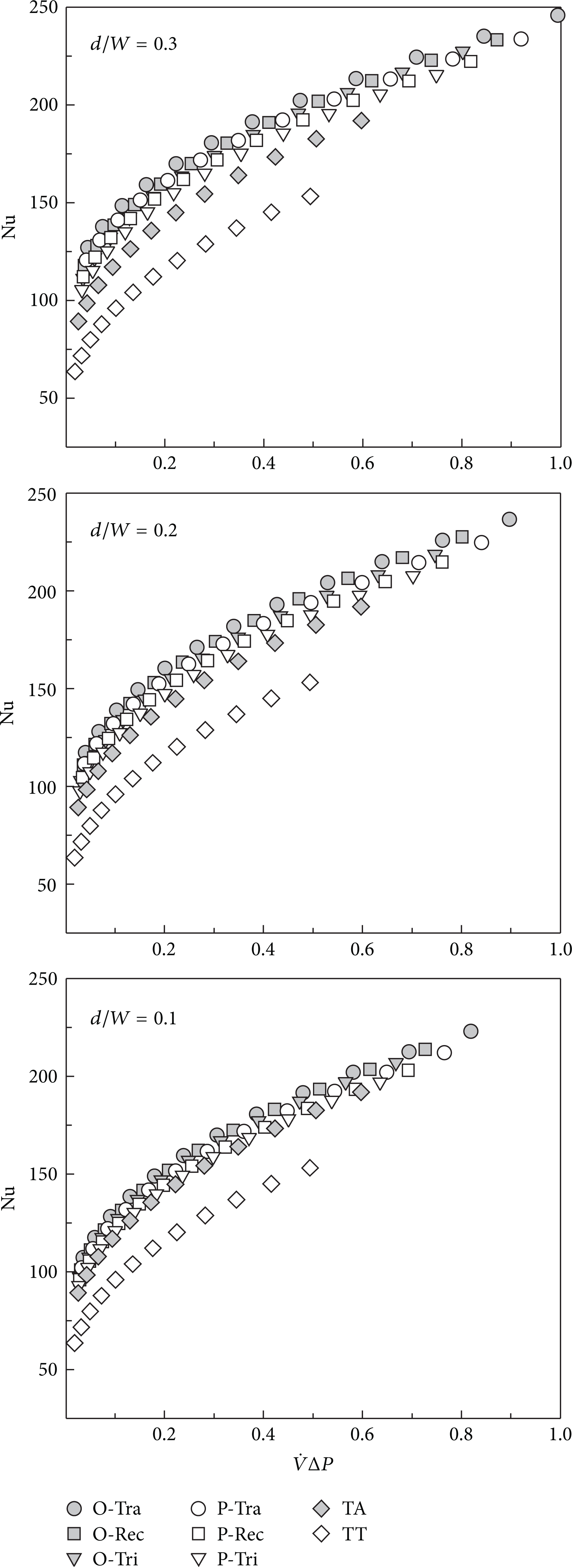
Nusselt number versus pumping power (
6. Conclusion
This paper has investigated the influences of the modified twisted tape with triangle/rectangular/trapezoidal wings (O-Tri/O-Rec/O-Tra/P-Tri/P-Rec/P-Tra) on the heat transfer, friction factor, and thermohydraulic performance characteristics. It is found that, at the given Reynolds number, O-Tra/O-Rec/O-Tri/P-Tra/P-Rec/P-Tri consistently provide higher heat transfer, pressure loss, and thermohydraulic performance than TA and TT. In addition, at a similar operating condition, the modified twisted tapes with opposite wing arrangement (O-Tra/O-Rec/O-Tri) perform higher thermohydraulic performance than the tapes with parallel wing arrangement (P-Tra/P-Rec/P-Tri).
Conflict of Interests
The authors declare that there is no conflict of interests regarding the publication of this paper.