
Abstract
We present the design and analysis of augmentation channels to increase the efficiency of shrouded marine current turbines in conditions of low intensity flows. These turbines are part of a prototype of a floating device composed of wind and marine current generators for generating renewable energy. It intends to exploit renewable energy resources in an integrated manner using wind and current turbines in offshore plants optimizing the economic investment.
1. Introduction
Marine energy generation has been pushed up recently with the installation of diverse systems for the use of tidal, wave, and marine current energy. Specifically marine current turbine technology is taking really serious consideration among research groups and companies. Projects like the SeaFlow (300 KW) at Lynmouth on the North Devon Coast or the more recent SeaGen (1.2 MW) in Strangford Narrows, Northern Ireland, prove the feasibility of this type of generation [1, 2].
Integration of wind turbines (WTs) and marine current turbines (MCTs) tries to optimize power generation and to achieve higher levels of performance using multivariable control techniques and greater actuation capacity on the system.
Our research group has designed and implemented a hydro-wind kinetics integrated module for renewable energy generation (HYWIKIM) prototype for the integration of MCTs and WTs generation in a single offshore floating system [3]. This integration presents two advantages. The first one is that we can take advantage of the floating support system used for wind generators, installing below the waterline two equally dedicated marine turbines to generate electricity. In this sense, and with small modifications for the integration of the turbines, the civil work investment done for the offshore wind turbine is shared. Also the main power collection system is shared by both systems.
The second advantage is that MCTs could be used in two ways: as power generators and also as actuator elements to face critical or severe open sea conditions threatening system stability, with aid of an intelligent multivariable control system.
In this paper we address the problem of the integration of the MCTs in our floating generation prototype. The mechanical design of augmentation channels (ACHs) to increase the efficiency of shrouded MCTs is analyzed. In Section 2 modeling and control considerations of the prototype are discussed. Section 3 presents aspects centered on the MCTs subsystem and the increase of its generation capacity, particularly on the increase of its power efficiency. In Section 4 a structural design based on shrouded turbines and results of simulations using CFD software tools are presented. Section 5 presents a cost justification of the use of ACHs. In Section 6 relevant conclusions can be found.
2. System Modeling
Wind turbines and marine current turbines share the same physical principle that allows energy generation [2]. It aims to harness the kinetic energy resulting from wind and sea currents. Marine current turbines have the advantage that marine water density is approximately 800 times higher than that of the air, providing more favorable conditions for power generation (1). Other features specific to MCTs are the loads and ranges of flows they have to bear and the effects of cavitation:
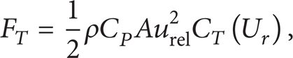
where F T is the thrust force. ρ is the fluid density. C p is the Betz factor. A is the total area swept by the rotor. U r is the relative velocity between the incoming flow and the turbine. C T (U r ) is the thrust force coefficient depending on control strategies.
Dynamics of a complex floating system with 6 degrees of freedom can be modeled by a nonlinear mass-spring-damper system subject to variable loads due to winds, waves, and marine current hydrodynamic flows. Under certain conditions of higher than normal wind speed, conventional pitch control techniques introduce negative damping in the movement of the floating structure. Pitch angle variation of the blades in order to regulate active power generated can result in uncontrolled resonance oscillations of the floating structure due to decreased opposition to wind. This phenomenon was found in tests conducted at the Ocean Basin Laboratory at Marintek in Trondheim [4–6].
Motion of a system with 6 degrees of freedom can be described by the following six coordinates:

Three of these six independent coordinates describe the translation movements on axes x, y, and z (surge, sway, and heave). The three other coordinates describe the pitch, roll, and yaw rotation movements Φ, Θ, and Ψ (Figure 1).

HYWIKIM integrated generation module.
On the other hand, the dynamic equation of a system with j degrees of freedom in motion around a stationary point in a fluid can be described by

where qk is the kth coordinate of the body. m jk are the rigid body mass and inertia parameters; τ j H are hydrostatic forces. τ j R are radiation forces in the form of waves by the movement of the body. τ j D are diffraction forces due to waves breaking against the body. τ j A are actuator forces. τ j E are other external forces.
In our approach we take into account weight, wind, current, mooring lines, and wave and drag forces. The floating system can be considered a floating spar buoy platform, with a mooring system composed of three catenary mooring lines. For detailed information on modeling and control of this type of platforms see [7, 8].
The problem of controlling WTs and MCTs has been usually discussed separately, taking into account control criteria specific to each of the generators [2, 4–6]. In our model the control system must be of multivariable nature due to the amount of coupled inputs and outputs as well as variables of interest to be considered [9–11]. Some attempts at solving this kind of problems by decoupled SISO control loops do not take into account important impacts on power produced, blade root, tower, and hub loads. Our integrated system approach must take into account the complexity of floating systems [7, 8, 12], increased by the coupled interaction of both types of generating systems, WTs at the top of the floating system and MCTs at the bottom.
Due to the possible combinations of variable gap between the thrust vectors of wind and currents, the two resultant vectors could act sometimes in an opposite or a superimposed manner at the top and bottom of the floating system, in a full range of 360°, affecting eventually the system stability (Figure 2).
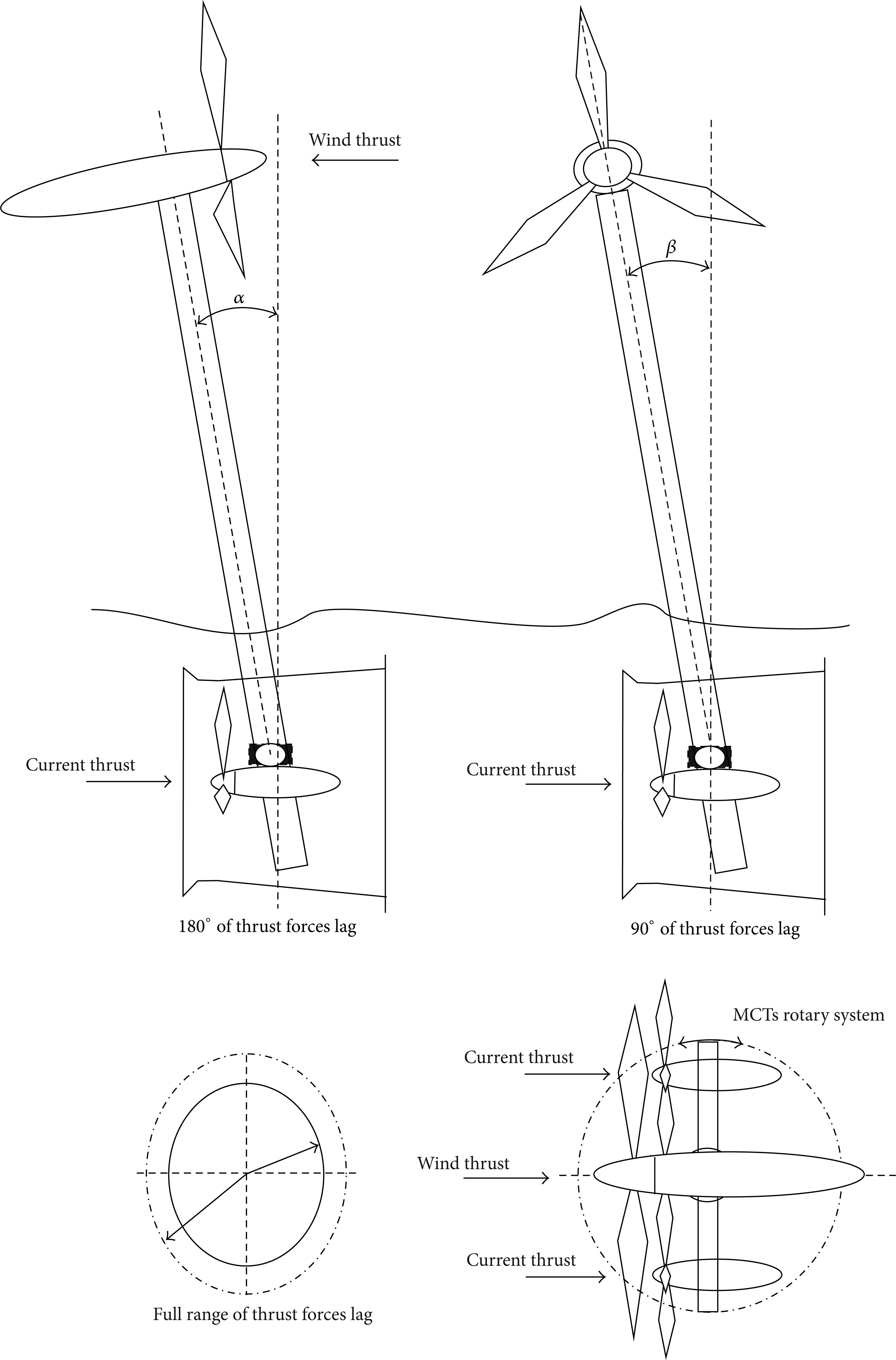
Pitch and roll movements and thrust forces lag.
From a control engineering perspective, comparatively to other proposals, our approach increases the actuation margin over the floating system through two MCTs acting in two different modes: (a) contributing to increase generation capacity and at the same time the overall stability of the system and (b) in critical conditions of adverse weather, contributing exclusively to the general stability of the system by the reversible operation of the MTCs.
Figure 3 shows a block diagram of the proposed control structure. The control variables are torques of the wind turbine Twt and current turbines Tct1 and Tct2 and pitch angles for each one of the blades of the wind turbine, βwt1, βwt2, and βwt3, and the two MCTs, βct11, βct12, βct21, and βct22, controlled individually. The output variables are pitch angle α and roll angle β with respect to the buoyancy center of the floating structure; angular velocities of the rotors, wwt, wct1, and wct2; and obviously the generated powers Pwt, Pct1, and Pct2. Vin and Cin represent, respectively, the interaction between the WT and MCT1/MCT2 with the floating structure. This control strategy is being tested in our prototype and will be published in the near future.

Control block diagram.
3. Floating System Prototype Design
We have implemented a multifunctional buoy based system as a test bench for integrated generation, control, condition monitoring, fault diagnosis, and predictive maintenance of renewable power generation systems. It will be used as well for the monitoring of marine parameters. This system integrates and combines offshore renewable electricity generation from both wind and marine currents turbines (Figure 4).

CAD design of the HYWIKIM prototype.
Although some ideas of integration are being raised [13], from the authors knowledge, never before an integrated floating system like HYWIKIM has been proposed.
Below the waterline a turning system with two turbines has been designed. This design allows facing the input current adequately and also the passage of both the power generated in the marine turbines and the data coming from the current sensors through the use of a rotating electrical connector (slip ring).
The rotating axis for the MCTs and rudder system was also modeled in Orcina Orcaflex. Lift and drag coefficients, corresponding to a NACA 63-012 rudder, were introduced in the model to implement the rudder. Figure 5 shows parts corresponding to the rotating system.

MCTs rotating system.
The interest to expand the usage scenarios of the HYWIKIM system is a motivating factor to intensify research on the increase of efficiency of MCTs. With this objective we have developed a procedure of design, simulation, and implementation based on the installation of augmentation channels (ACHs) in the MCTs.
4. Augmentation Channel Design
For propeller-type turbines efficiency is defined as the ratio between the turbine power and the power of an unconstrained uniform flow through the turbine area. The efficiency limit of Betz (59.3%) is usually considered for this kind of turbines.
The Betz model considers that the fluid flow remains rectilinear when passing through the turbine and maintains a uniform distribution of the fluid pressure. This consideration overestimates the forces and torque applied to the turbine and overestimates the turbine's power and its efficiency. The case is that the fluid streams experience a deflection from the rectilinear direction, changing their motion to curvilinear trajectories and reducing their pressure on the turbine. It is possible to get a more accurate efficiency limit by taking into account these considerations.
New models like the GGS model [14] have been proposed. In the Betz model the center of pressure is at a distance R/2 from the axis, where R is the turbine radius, whereas in the GGS model the center of pressure is at a distance 0.37R from the turbine axis, much closer to the turbine shaft. Then the torque is greater in the Betz model than in the GGS model as a result of this difference.
One way to increase the efficiency of these turbines is to install augmentation channels (ACHs) to accelerate flow speed. With regard to this augmentation devices different terms such as duct, shroud, wind-lens, nozzle, concentrator, diffuser, or ACH are used synonymously [15]. Some other reports on channel augmentation can be found in [16–19].
Ducted turbines are not subjected to the Betz limit. For ducted turbines the theoretical limit depends on (a) the pressure difference between duct inlet and outlet and (b) the volumetric flow through the duct. These factors depend on the shape of the duct and the ratio of duct area to turbine area.
Previous investigations by others [20, 21] have found a theoretical limit for a diffuser-augmented wind turbine of about 3.3 times the Betz limit, and a model diffuser-augmented wind turbine has extracted 4.25 times the power extracted by the same turbine without a diffuser.
The degree of the performance enhancement depends on several factors such as the diffuser shape and geometries and also the wind/water condition at the mounting site. Some of the geometric parameters considered are shown in Figure 6.

Augmentation channel classification.
Computational fluid dynamics (CFD) is a branch of fluid mechanics that uses numerical methods and algorithms to solve and analyze problems that involve fluid flows.
There are several commercial software packages available for finite volume CFD simulations. In this research the numerical simulations were performed with ANSYS CFX using near-wall calculations.
In order to increase the energy efficiency of MTCs to be installed in the HYWIKIM prototype, a series of simulations to find the optimal model have been performed. Since CFD requires high CPU resources a different approach has been used in order to economize computation time. An initial empty diffuser case is studied in order to determine the most suitable geometry for the ACH. This design is validated by a momentum source model in order to simulate the turbine energy consumption and then a final simulation with the complete turbine geometry is performed. An optimal geometry around this initial case is determined by the empty diffuser case study.
4.1. Empty Diffuser Case
The models used in the simulations correspond to Figure 6 types a, b, c, d, e, and i. The inflow velocities for all trials have been set to a value of 0.3 m/s considering the characteristics observed in the initial location at the coast of Valencia.
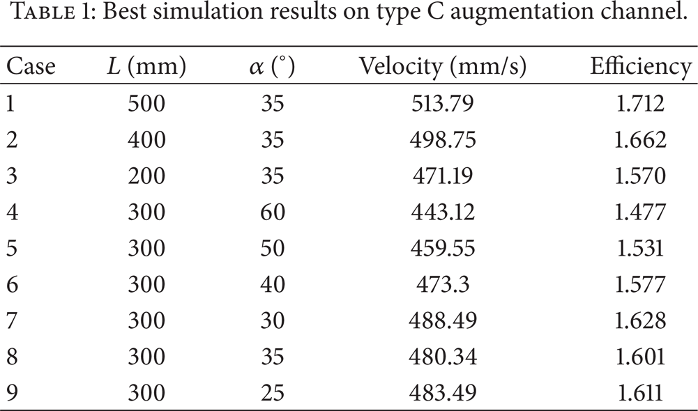
Our first studies focused on inlet-diffuser type C ACH (Figure 7) making variations of geometric parameters L andα. Results from these initial simulations are presented in Table 1.
Best simulation results on type C augmentation channel.
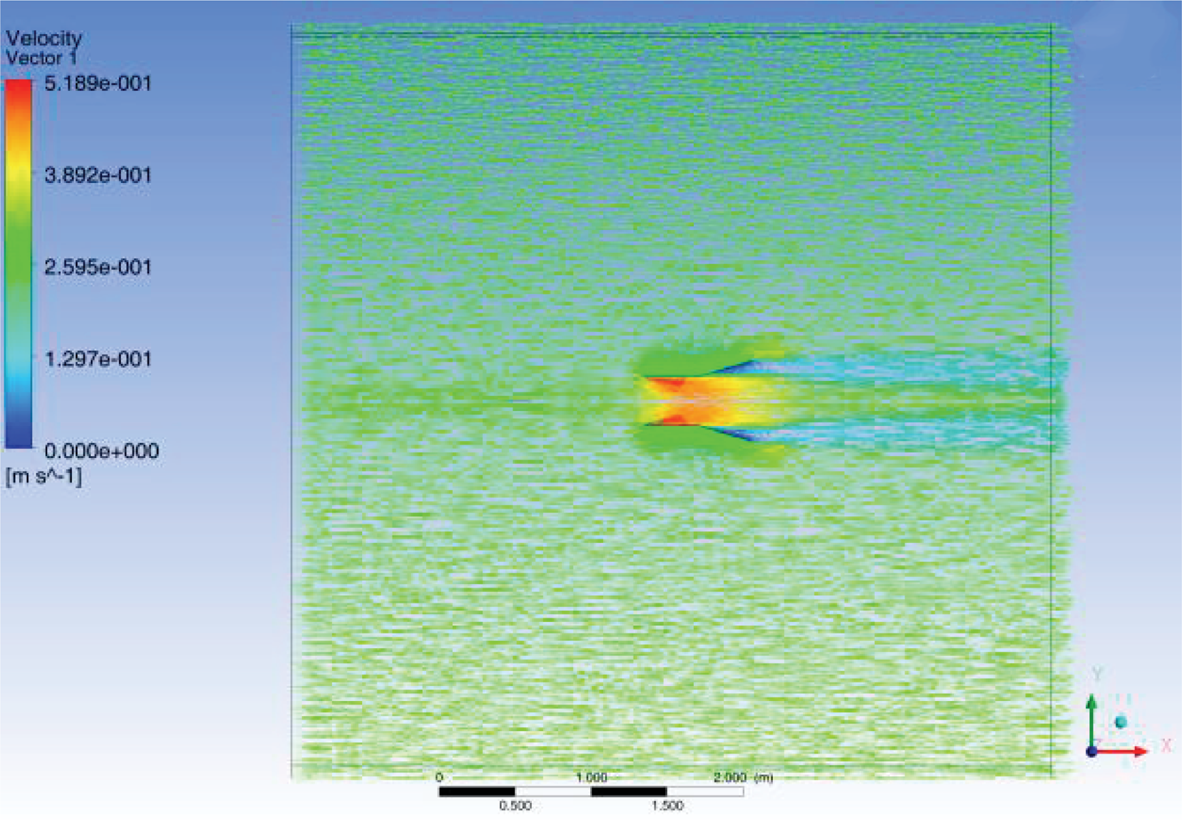
Type C augmentation channel simulation. Velocity vectors on symmetry plane.
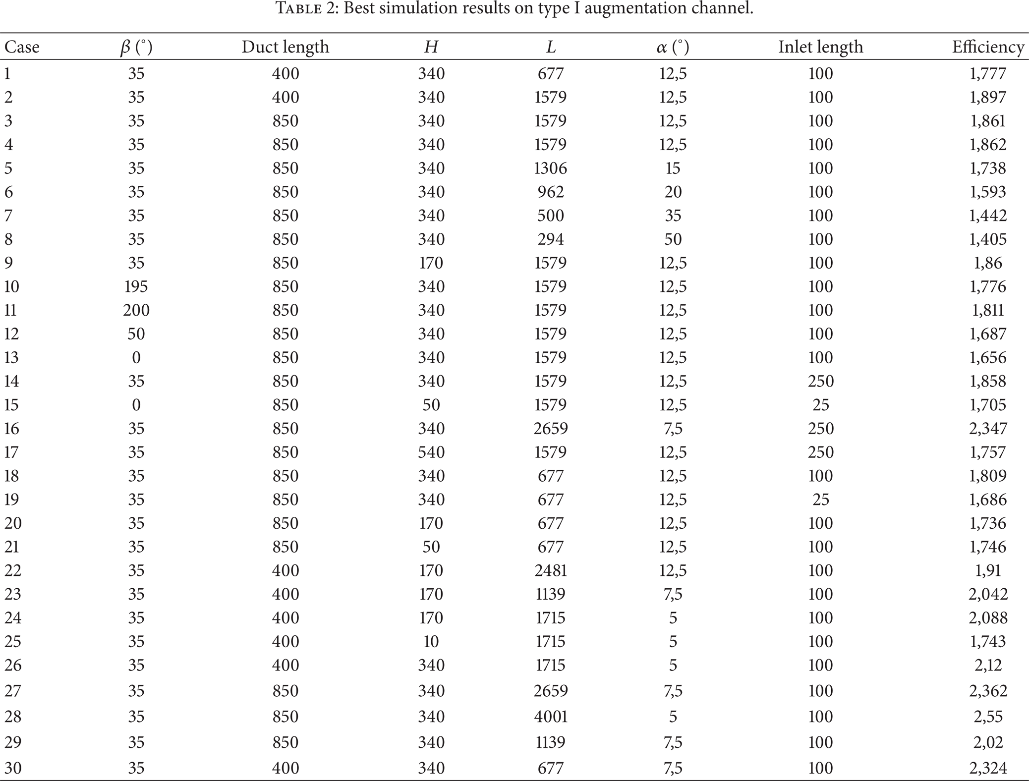
These results are not satisfying enough for our prototype requirements and more complex geometries are studied. Simulations based on the above results adding geometric parameterβ associated with the use of nozzle-inlet-diffuser-brim type I ACH (Figure 8) were subsequently conducted. A parametric study was performed and is reflected in Table 2. ANSYS software allows performing this kind of parametric study establishing geometry dependency on the different parameters and selecting ranges and constraints.
Best simulation results on type I augmentation channel.
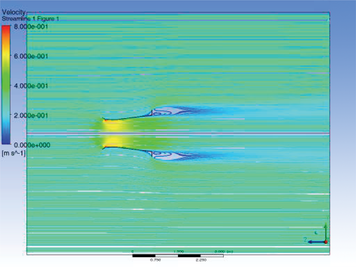
Type I augmentation channel simulation. Streamlines reflected at symmetry plane.
Since the model is axisymmetric, a portion of 6° of the whole system is used for simulation, allowing a more refined mesh without extending calculation time.
The best performance is achieved on study case 28 with a 2.55 ratio. In order to optimize also the economics of the system, volume and length of the different studied geometries are calculated and included on ratios in order to evaluate the best solution which achieves at least a ratio of 2 and uses less volume and materials (Table 3). Case 23 is the smallest system that accomplishes the ratio requirement.
Study of efficiency related to geometry.

These cases are obtained by a geometry optimization process using Siemens NX and ANSYS flow solver. The objective is to maximize the efficiency under geometric restrictions of limit values allowing the change on certain dimensions. Starting from an initial flow simulation, geometry optimization starts a process based on Rosenbrock's method [22] and tries to find a local maximum for the planned index until no more improvements are found.
Figure 9 shows the graphical evolution of the design variables along the optimization process. The algorithm changes the dimensions searching for an improvement at each simulation step. Figure 10 shows the evolution of the index along the optimization process. On step 30 (starting from initial step 0) the obtained value is the same as that on step 27 and no further improvements are achieved, ending the optimization process.

Design variables evolution along optimization process.
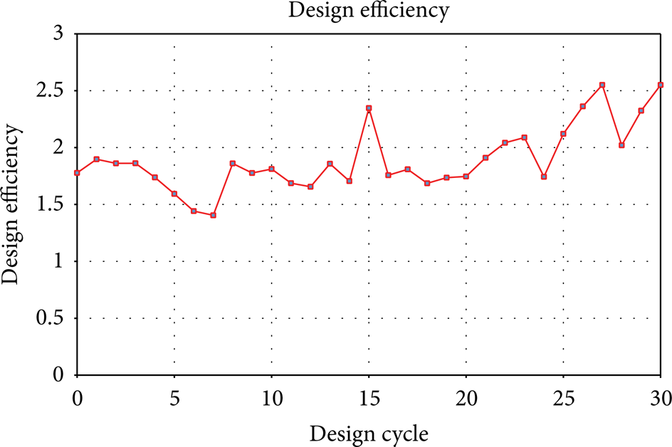
Optimization index evolution along optimization process.
4.2. Momentum Source Model
In [23, 24] the use of diffusers to enhance the performance and viability of hydrokinetic turbines is studied. To simplify the problem, the turbine is modeled as a momentum source region.
The turbine rotor represents a challenge for numerical modeling due to its complex geometry and rotational motion. This is even more difficult if an optimization problem is being faced since numerous simulations are going to be taken into account. Total inclusion of a turbine rotor would extend the computation time considerably in an optimization problem. Since a complete resolution of the flow through the rotor is not required for the optimization of the ACH, it is possible to simplify the system with the momentum source model.
The turbine affects the final flow solution introducing a nonlinear effect. The pressure disturbance from the turbine depends on the velocity which depends on the diffuser outlet pressure itself. Momentum source modeling is valid for simulating this pressure change.
On this method a subdomain is defined inside the diffuser where the turbine should be. On this subdomain the turbine extracts part of the energy from the fluid. To model this we introduce a momentum source term in the cylindrical region enclosing the rotor. In [25] a detailed study of blade element momentum theory is provided, a momentum source modeling strategy common to wind turbines. In [26] the rotor is modeled as an array of discrete momentum source points which was derived empirically.
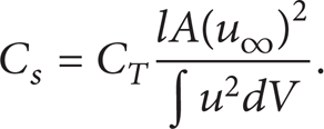
When the fluid passing through the turbine losses energy that a turbine would normally extract, the momentum source is given by
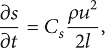
where s is the momentum per volume unit removed from the fluid, ρ is the density, u is the local velocity, l is the streamwise length of the turbine region, A is the turbine area, V is the turbine volume, and C s is the momentum source factor, a constant that is related to the thrust coefficient of the turbine:
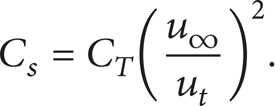
If speed variations within the turbine region are assumed to be small, this reduces to
Results from this optimization are reflected in Table 4 and some graphical results are shown in Figure 11. The subdomain is reflected in this figure as having a streamwise length of 100 mm. Some differences between the empty case and this simulation are perceived. The pressure drop is less pronounced causing a softer change on the flow stream.
Simulation results for the momentum source model.

Simulation on type I augmentation channel. Streamlines reflected at symmetry plane. Momentum source model.
Comparing results from the empty diffuser case it is remarkable that a decrease on the efficiency is detected since on the empty diffuser case the effect of the turbine is not modeled.
4.3. Frozen Rotor Model
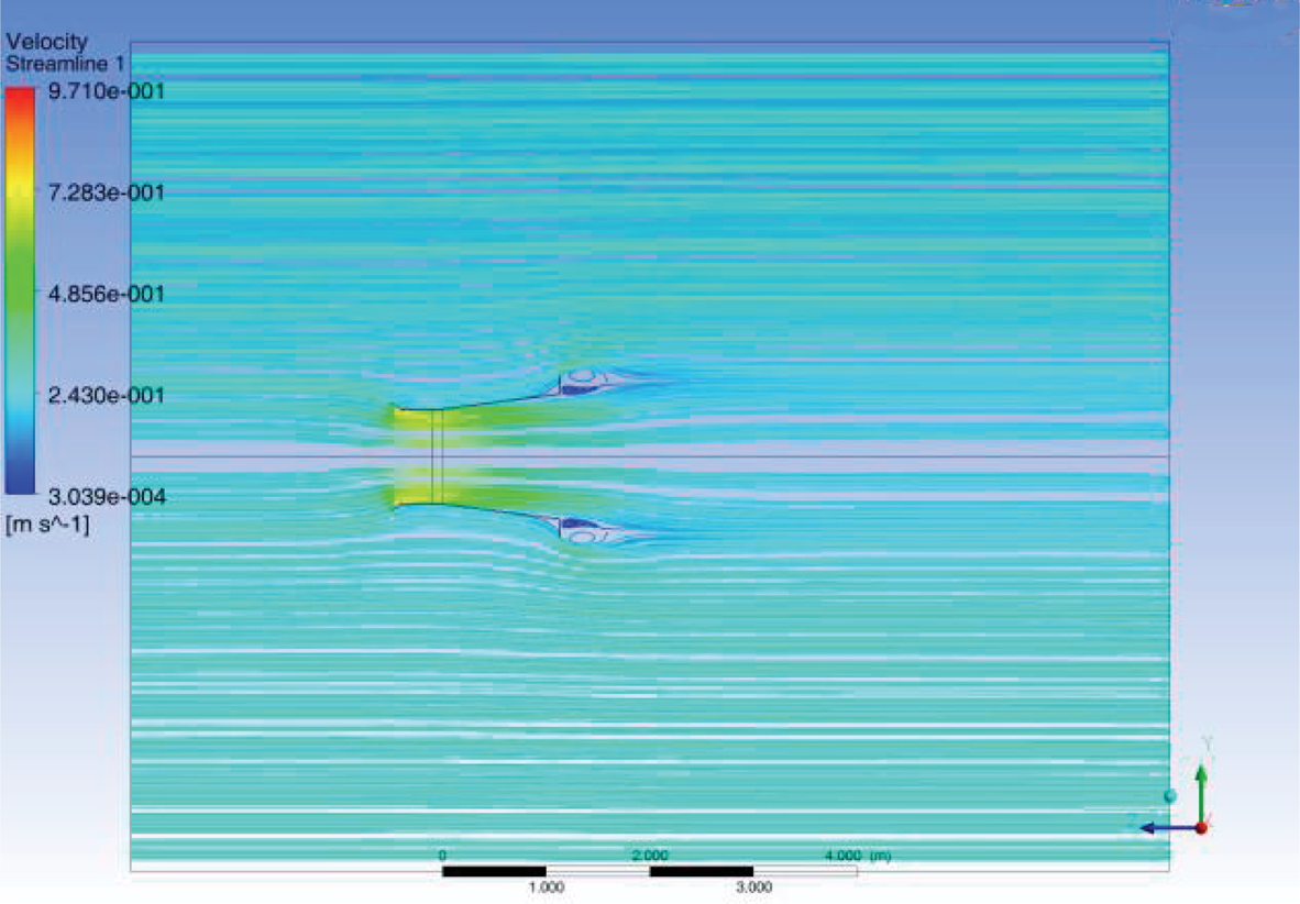
A simulation was performed in order to get a detailed picture of the current streamline in the turbine and pressure on the walls of the system (Figure 12).

Stream lines simulation results for frozen rotor modeling.
The frozen rotor model is commonly used in wind turbine simulations; it reduces simulation time and produces an approximate solution. The rotating region does not rotate during the simulation. Rotating and associated momentum terms are imparted to the flow instead. A portion around the blades is defined as a separated subdomain which is defined as rotating while the whole environment surrounding it is defined as static. An interface is defined between rotor and stator.
In this case the rotating speed is considered to be 70 rpm which is the expected inlet velocity for the current turbine. The average speed obtained at the ACH validates the momentum source results.
5. Discussion
Several research works [15–21] consider favorable aspects of the use of augmentation channels in hydrokinetic turbines. One of the main advantages is a substantial increase in the flow rate because of the depression originated in the interior of the channel. The flow rate is a variable involved exponentially by a factor of three in the power generated by the turbine, and consequently, more power means a greater return of the investment.
It is true that augmentation channels lose effectiveness when they are not well targeted towards the ocean current, but in our design the turbines under normal conditions are well targeted since they have a rotating system powered by a rudder (Figure 13).

Augmentation channel implementation process.
The speed range of water currents suitable for the operation of hydrokinetic turbines is known to lie between 1 and 3 m/s. Below the lower limit its use is not viable from an economic point of view, and above the upper limit structural loads and cavitation effects appear that can compromise the integrity of the turbines. The incorporation of augmentation channels allows for the use of these turbines in many other parts of the coast that otherwise would not be economically feasible [27].
Another advantage of the flow speed increment produced by augmentation channels is that it permits the elimination of the low-speed stages of the gear box. Since these stages are the most expensive of the gear box, there is a direct size and cost reduction in the machine [28].
Although applications of such devices were not successful with big rotor diameters wind turbines, owing to many practical challenges such as tower-head placement, variable orientation, weight, and size, ACHs in marine turbines appear more suitable because of their underwater placement [29].
In our view the installation of ACH has a beneficial effect in the structural stability of the floating system. An increase in mass of the floating system due to the weight of the hydrokinetic turbines and augmentation channels de facto makes a more balanced distribution of masses which favors the structural stability of the floating system.
In [30] a planning, operation, and maintenance model for tidal turbine farms is proposed. The system is modeled using life-cycle assessment, incorporating a variety of time-dependent variables. Model components include farm construction and planning, operation strategy, regular maintenance, and emergency maintenance. Factors affecting O&M cost are more than eighteen including component lifetime and failure rate, environmental factors, or farm configuration. Augmentation channel cost would be one more of them, not especially significant considering the derived benefits.
In our prototype, augmentation channel cost is 10% of that of the whole system. This amount is expected to be much reduced when the system is scaled to a commercial size. For this implementation different materials such as fiber composites will be used resulting in an 8th-fold weight reduction compared with stainless steel [31, 32].
6. Conclusions
This paper presents a prototype for the integration of wind turbines and marine current turbines in a single floating structure.
Using the same structure for both generating systems we are able to increase the total generated power and optimize the civil work investment. Moreover, the incorporation of marine current turbines provides passive stability improvements with the additional underwater weight as well as additional actuator capacities for active stabilization of the integrated system. The two integrated marine current turbines can act reversibly to help control the stability of the floating system, when strong winds and critical sea conditions require it.
This paper focuses specifically on the analysis and design of augmentation channels to increase the efficiency of the shrouded marine current turbines. Our simulation results show how the efficiency improvement derived from the augmentation channel use expands the economic feasibility of our system to marine areas with lower current resources. In particular, for type C augmentation channel the efficiency increase was 1.71 and for type I a maximum efficiency of 2.55 was achieved. For this last model a parametric variation analysis was conducted. From the simulations we conclude that the best option for our prototype is based on the use of type I augmentation channel. Finally, a momentum source model was used to validate the system, taking into account the turbine effect. A simulation, modeling the whole blade geometry, was performed in order to validate the final design. Finally we have shown how augmentation channels use is fully justified from an economic point of view in the construction of the proposed hydro-wind generation system.
Conflict of Interests
The authors declare that there is no conflict of interests regarding the publication of this paper.
Footnotes
Acknowledgments
The authors would like to acknowledge the collaboration of the Valencia Port Authority (Valencia Port) and the Real Club Náutico de Valencia.