
Abstract
Additive manufacturing (AM) is increasingly applied in the development projects from the initial idea to the finished product. The reasons are multiple, but what should be emphasised is the possibility of relatively rapid manufacturing of the products of complicated geometry based on the computer 3D model of the product. There are numerous limitations primarily in the number of available materials and their properties, which may be quite different from the properties of the material of the finished product. Therefore, it is necessary to know the properties of the product materials. In AM procedures the mechanical properties of materials are affected by the manufacturing procedure and the production parameters. During SLS procedures it is possible to adjust various manufacturing parameters which are used to influence the improvement of various mechanical and other properties of the products. The paper sets a new mathematical model to determine the influence of individual manufacturing parameters on the polymer product made by selective laser sintering. Old mathematical model is checked by statistical method with central composite plan and it is established that old mathematical model must be expanded with new parameter beam overlay ratio. Verification of new mathematical model and optimization of the processing parameters are made on SLS machine.
1. Introduction
Additive manufacturing allows production of parts of very complex shapes, the making of which had been limited until these procedures were developed. Additive procedures are being intensively developed from day to day. Here the number of available materials is limited. Material properties differ a lot from the properties of the materials of finished products. Therefore, it is necessary to know the mechanical properties of the product material [1]. In selecting the processing procedures it is necessary to take into consideration four criteria: the desired material, size and number of products, time of manufacturing, and cost of production [2].
Prototypes made by selective laser sintering (SLS) are increasingly used as products, which means that they have to have high dimensional accuracy. However, accuracy is difficult to predict, since it depends on many parameters: accuracy of STL model in conversion from CAD model, cutting into layers, machine resolution, beam offset, layer thickness, material shrinkage, laser beam speed, laser power, temperature of working platform, and hatch distance.
Laser parameters can be used to affect the sintering procedure and the properties of the manufactured product. The quality of the surface, mechanical properties, dimensional accuracy, and time of manufacturing are the most common reason for the need to change the parameters. The parameters can be changed separately for the contour (external layers), that is, the product hatching (product interior). Improved connection of particles (sintering), as well as the mechanical properties, is affected by the energy density of the laser beam not only on the external layers, but also in the interior. According to many past studies the energy density depends on the power and speed of the laser beam and on the hatch distance or on the laser beam diameter, which is calculated according to the following equation: [3–8]

where ED [J/mm2] is the energy density, P [W] is the laser power, v [mm/s] is the laser beam speed, h [mm] is the hatch distance, and d [mm] is the laser beam diameter.
The value of the laser power during the sintering procedure depends on the type of material and the thickness of layer which is applied by the levelling roller. Laser power and laser beam speed during the making of the contour are somewhat lower in relation to the power and speed during the making of the hatching of individual layer. By changing the laser beam speed, the energy input into the material and the time of product manufacturing are changed as well [5–9].
2. Selective Laser Sintering
In SLS procedure the laser beam is directed by a mirror and marks the cross-section of the product on the powdery material located on the working base. Under the action of the laser beam thermal energy the powdery material softens and this results in mutual sintering of material particles and fusion of the newly applied layer of powder with the previously sintered layer [5, 10, 11].
Apart from the melting of new powder particles, in the next layer the laser beam has to sinter at the same time this new layer with the already existing one. Because of different thicknesses of the layers and the possibility of using several types of materials of different thermal conductivity on SLS equipment, it is necessary to ensure adequate energy density (ED) input by the laser beam in order to sinter the material at all and to connect this one with the previous layer (Figure 1). Since the layer thickness on the machine Formiga P100 is 0.1 mm the laser beam melts a somewhat thicker layer of powder and does it every time in every layer. In melting the powder volume is reduced. It is also necessary to set appropriate power for the layer thicknesses in order to avoid excessive sintering (Figure 2).

Impact of laser beam on the material [12].

Power selection depending on the layer thickness.
When applying the finish layer of the product, the levelling roller is used to apply several protective layers of powder (5 mm). The working chamber with the product is left in the machine for about 2 h, in order to let it cool gradually. The product is not yet suitable for handling, so it is left in powder outside the machine to let it cool completely to the room temperature. This influences the dimensional accuracy and reduction of heat deformations. Cooling of the product should take as long as the production does. After the product has cooled it can be taken out and cleaned from excess powder [6, 11].
2.1. Laser Parameters
Laser parameters can affect the sintering procedure and the properties of the product. Surface quality, mechanical properties, dimensional accuracy, and time of manufacturing the product are the most common reasons for changing the parameters. Parameters can be adjusted separately for contour and separately for the interior (hatching) of the product. The hatching parameters are the same as the contour parameters with different settings [6].
Laser Power. The amount of laser power P [W] during the sintering process depends on the type of material and the thickness of the layer which is applied by the levelling roller. In making of the contour the laser power is somewhat lower (approximately by 5 W) in relation to the power during the making of the layer hatching [6].
Laser Beam Speed (Scanning Speed). The speed of the laser beam v [mm/s] is also a parameter which can be regulated regarding the making of the contour or the product hatching. In making of the contour the speed of the laser beam is lower than in making of the hatching. With the change in the laser beam speed the energy input in the material and the time of making of the product are changed as well [6].
Laser Beam Diameter. In SLS procedures the laser beam is directed downwards with a certain diameter and it radiates the powder surface. The beam diameter d of the Formiga P100 machine of the company EOS is 0.42 mm. However, the diameter of the area in which the particles are sintered is somewhat larger than the physical diameter of the beam (effective sintering diameter de) (Figure 3) [6].
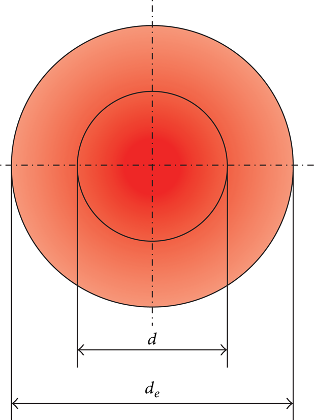
Physical d and effective de diameter of the laser beam [6].
Since the laser power and the speed of the laser beam are different in making of the contour, that is, hatching of the product, there is also difference in de of the contour, that is, of the hatching (d ek ≠d ej ). For easier presentation, the effective and physical diameters of the laser beam are presented as a circle. Their actual appearance depends on x and y rotation of the scanning mirror [6].
Hatch Distance. Hatch distance h is presented in Figure 4. If the hatch distance is greater than the laser beam diameter between the laser runs some unsintered material remains.

Hatch distance [13].
3. Experimental Part
3.1. Tensile Properties Depending on the Adjustment of Parameters for the Contour of the Product
Parameters can be adjusted separately for the contour and separately for the product hatching. In the first phase of verifying the previous equation the parameters have been changed (Table 1) for the product contour and the influence of these parameters on tensile strength, yield strength, and elongation at break has been determined. The test (Figure 5) leads to the conclusion that mechanical properties vary slightly, concluding that due to the larger surface (i.e., volume) the hatching parameters rather than the contour parameters have greater influence on the product properties. The test specimens have been made with a layer thickness of 0.1 mm.
Relation of parameters for setting the contour of the product and mechanical properties.


Tensile properties depending on the adjustment of parameters for the contour of the product: (a) tensile stress and (b) tensile strain.
For determining the mechanical properties the Messphysik Beta 50-5 testing machine is used. The control unit is an EDC 100, with a maximum loading force of 50 kN. The testing was carried out at the temperature of 23°C. For determining the tensile properties the test specimen is clamped by the jaws of the tensile testing machine and extended with force F, at speed v = 5 mm/min, as defined by standard ISO 527:2012. For the testing of flexural properties, the test specimen has to be supported by two supports and loaded in the middle by force F according to standard ISO 178: 2011. The testing speed was v = 5 mm/min.
3.2. Properties Depending on the Adjustment of Parameters for the Hatching of the Product
According to the available literature the main hatching parameter which affects the product properties is the energy density ED, which is calculated according to (1).
Due to contradictory opinion in the studied literature preexperiments were carried out and they are used to determine the dependence of single parameters.
For the experiment the central composite plan which allows modelling of polynomial of the second order and the shape of the response surface has been selected. The experiment determined the influence of three parameters (laser power, speed of the laser beam, and hatch distance) on mechanical properties (tensile and flexural strength) of the product obtained by SLS procedure. Software program Design Expert by module ANOVA (variance analysis) has been used.
The experiments were carried out with material PA 12, that is, PA 2200, with other processing parameters as follows:
chamber temperature 172°C;
layer thickness 0.1 mm;
beam offset 0.15 mm;
material shrinkage along x axis 3.4%, along y axis 3.4%, and along z axis at 0 mm 2.2% to z axis at 300 mm 1.6%;
alternating scanning direction;
included compensation of laser beam speed.
Before the experiment, a preexperiment was performed to determine the lower and upper limit of the following factors.
laser power, P = 5–25 W.
laser beam speed, v = 1000–3333 mm/s.
hatch distance, h = 0.15–1.6 mm.
It is necessary to carry out 19 experiment conditions (condition in the centre was repeated five times). The levels of factors (Table 2) have been determined according to the experiment condition matrix for the central composite experiment plan with two factors. Table 3 shows the results of the mean values of the mechanical properties. The linear curve for all properties has been selected as the approximation curve.
Levels of factors.

Measuring results.

The experiment under number 11 was immediately excluded from the analysis since it is not possible to make the test specimen with these parameters, that is, such low energy density.
Experiments numbered 3 and 15 have been excluded from further analysis since the analysis showed that the response in these points does not correspond to the model; that is, there are too large deviations of the strength values from other data.
3.2.1. Tensile Strength
Table 4 shows the results of the processing for tensile strength R m . In this case factor C, the hatch distance, is a significant factor (i.e., it affects the change of the tensile strength). In order for a certain factor to affect the change, the value in Table 4 in the last column should be smaller than 0.05.
Results of the variance analysis—tensile strength.

Prob. > F: is the risk of rejection of hypothesis H0.
Cor Total: is the sum of squares in model.
Table 5 shows the basic statistical data about the model. The R-squared (r2) is the measure of deviation from the arithmetic mean which is explained by the model. The closer r2 is to 1, the better the model follows the data. The calculation is done according to [14]

where r2 is the R-squared and SSD is the sum of square deflection.
Overview of statistical data about the model for tensile strength.
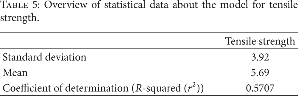
From the table it can be concluded that the deviation from the model is very large; that is, there is only 0.01% that the corresponding analysis follows the model.
Figure 6 shows the dependence of the tensile strength on the speed of the laser beam and the hatch distance. The power which was shown by the experiment to have the least effect on the tensile strength was taken as a constant and amounts to P = 21 W. Graphical presentation of the dependence of tensile strength on the laser power and the hatch distance is similar to the diagram in Figure 6 and has not been presented separately.

Dependence of tensile strength on the laser beam speed and the hatch distance at constant power.
From Figure 6 it may be concluded that with the decrease in the speed of the laser beam and the hatch distance the tensile strength is increased, although the R-squared shows that the model does not fully follow the data; that is, the tensile strength is also affected by some other influencing factors that have not been included in this preexperiment.
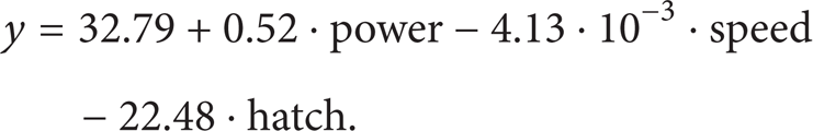
According to the regression coefficients mentioned in Table 6, the model for tensile strength can be described by (3) in the coded form and with (4) in actual factors:

For example, for A = 21 W (coded value = 1), B = 2667 mm/s (coded value = 0.67), and C = 0.45 mm (coded value = −1), expected value of the tensile strength will be 12.21 MPa.
Regression coefficients for tensile strength.

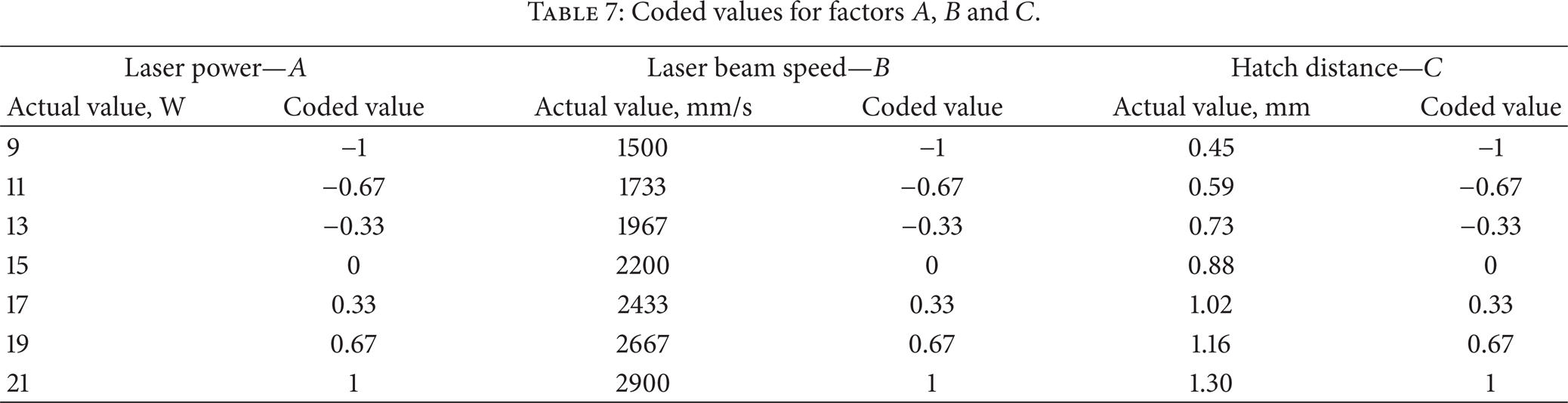
Table 7 presents the coded values of the experiment factors for the tested area.
Coded values for factors A, B and C.
3.2.2. Flexural Strength
Table 8 shows the results of processing for the flexural strength. The table leads to the conclusion that in this case as well the only influencing factor is the hatch distance, whereas the laser power and the laser beam speed have the same impact. However, as in the case of tensile strength the deviation from the model is too large and some other model or some other parameters that can reduce the deviation are necessary. Table 9 shows the statistical data.
Results of the variance analysis—flexural strength.

Overview of statistical data about the model for flexural strength.

Figure 7 shows the dependence of the flexural strength on the laser beam speed and the hatch distance. In this case as well the constant power P = 21 W has been taken. The graphical presentation of the dependence of the flexural strength on the laser power and the hatch distance is similar to the diagram in Figure 7 and has not been presented separately.

Dependence of flexural strength on the laser beam speed and the hatch distance at constant power.
It may be concluded from the figure that by reducing the laser beam speed and the hatch distance the flexural strength is increased, although in this case as well the R-squared shows that the model does not fully follow the data, that is, that the flexural strength is also affected by other influencing factors that have not been included in this preexperiment.
According to the regression coefficients mentioned in Table 10, the model for flexural strength can be described by (5) in the coded form and by (6) in the actual factors:

For example, for A = 21 W (coded value = 1), B = 1500 mm/s (coded value = −1), and C = 0.45 mm (coded value = −1), expected value of the flexural strength will be 27.4 MPa.
Regression coefficients for flexural strength.

The coded values of the experiment factor for the flexural strength are the same as for the tensile strength according to Table 7.
In order to reduce the deviation from the model and for the tensile and flexural strength many analyses have been carried out, but not one has proven to be appropriate, which leads to the conclusion that the parameters depend on each other, that is, that for the mechanical properties of the product there are factors which failed to be included in this model.
4. The Influence of Processing Parameters on the Product Properties
It was found from the conducted preexperiment that the parameters depend on each other and that there are still some other factors that affect the mechanical properties of the product, so that it may be concluded that it is necessary to set a new equation for the calculation of the energy density. The equation of the energy density ED should be expanded by the beam overlay ratio x which includes in itself the diameter of the laser beam and the hatch distance:

where ED [J/mm2] is the energy density, P [W] is the laser power, v [mm/s] is the laser beam speed, h [mm] is the hatch distance, and x is the beam overlay ratio which is calculated according to


where d [mm] is the laser beam diameter. On the machine Formiga P100 where measurements were conducted d is constant (d = 0.42 mm).
Figure 8 explains the new proposed equation for the influence of the parameters on the properties of the product; that is, it shows the scheme of scanning the powder particles by laser beam with the marked laser beam diameter d and the hatch distance h. At h<d (Figure 8(a)) there is excessive overlay (greater factor x), where the value of energy density is also too high, and this results in the reduction of mechanical properties; however, at h>d (Figure 8(b)) there remains unsintered powder and a mesh-like structure is achieved, so that a better case is the higher beam overlay ratio, that is, smaller hatch distance. Also, the beam overlay ratio should not be too large since this results in longer time of production.
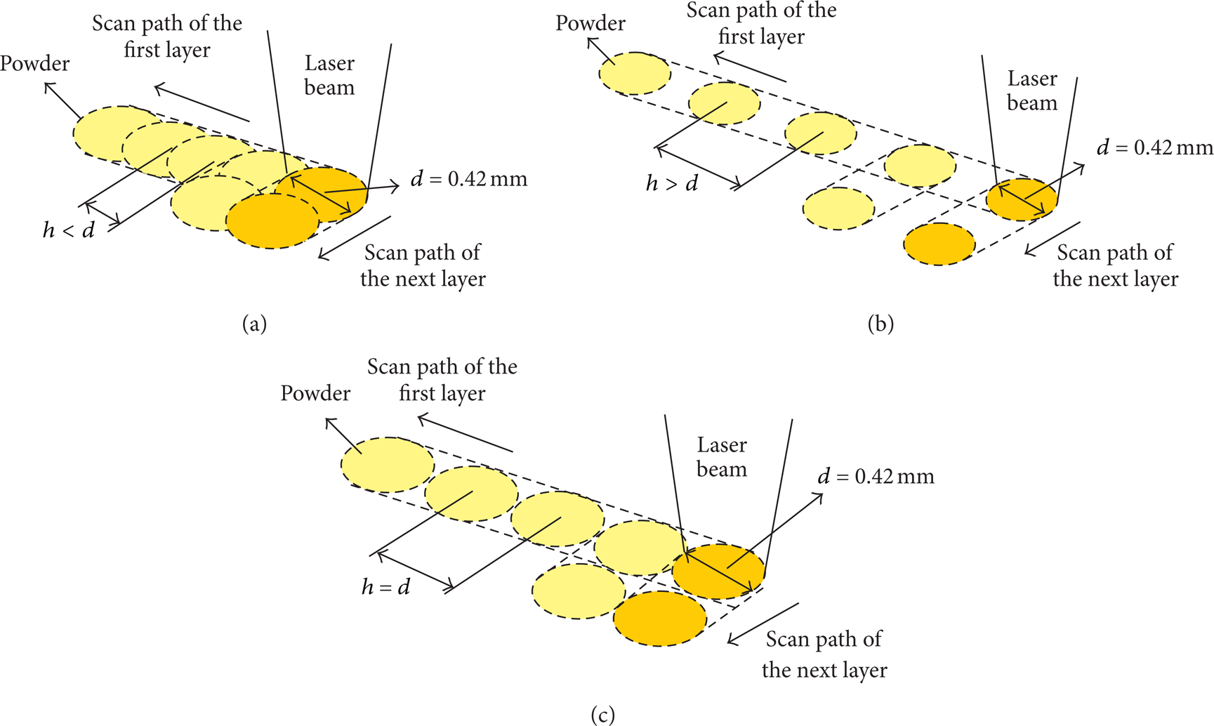
Scheme of the powder particles sintering: (a) h<d, (b) h>d, and (c) h = d.
Based on the conducted experiments it is proposed to take on the machine Formiga P100 the value of energy density ED = 0.05 J/mm2 for the manufacturing of products of good mechanical properties with a layer thickness of 0.1 mm. The new equation is confirmed by the orientation of the test specimens of 0°, 90° with a height of 10 mm and 80 mm for flexural properties and 150 mm for tensile properties.
However, it is difficult to select which value of laser power, laser beam speed, and hatch distance should be taken into consideration in order to obtain adequate energy density ED. Thus, Figure 9 shows the proposal of selecting the parameter in energy density 0.05 J/mm2 for Formiga P100, which can be also implemented for other machines used for SLS procedure.
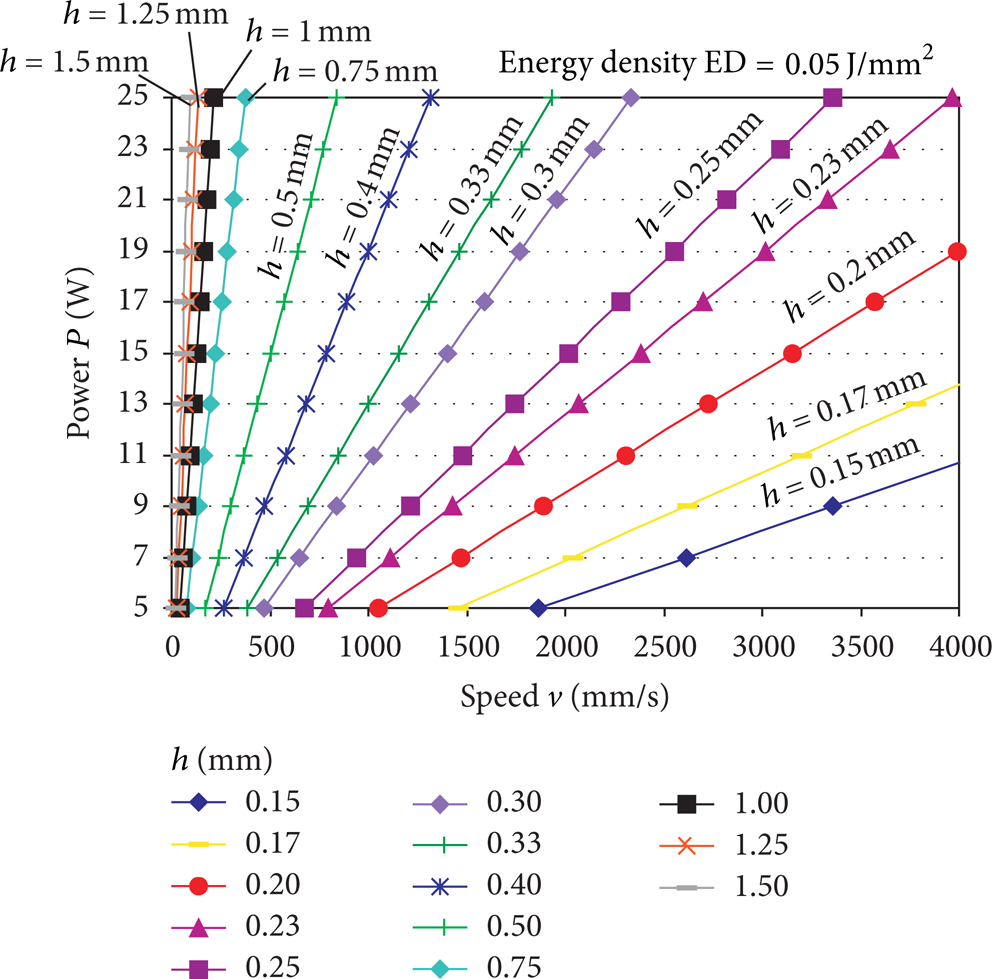
Determination of SLS procedure parameters at layer thickness 0.1 mm and energy density ED = 0.05 J/mm2.
5. Conclusion
During the process of making the product, using the selective laser sintering, it is possible to set various parameters that affect the properties of the final product. During the manufacturing one can thus adjust separately the parameters that make the contour and separately those that make the hatching of the product. From the conducted analysis it can be noticed that the mechanical properties are more affected by the parameters for adjusting the hatching of the product.
Past experiments were based on the equation for the hatching which connects the energy density with the laser power, laser beam speed, and hatch distance.
By implementing the central composite plan of experiment an analysis has been made and one can notice that in mechanical properties the only influencing factor is the hatch distance. However, in mechanical properties there is great deviation from all the models and R-squared does not follow fully the data (r2 = 0.5). In order to reduce the deviation from the models and for tensile and flexural strength many analyses have been carried out, but none has proven adequate, which leads to the conclusion that the parameters (power, speed, and hatch distance) depend on each other, that is, that the only relevant parameter for the product property is energy density and that there are factors that are not included in this model (e.g., laser beam diameter, beam shift, shrinkage coefficient, manufacturing strategy, etc.).
Regarding the working principle of the SLS procedure (Section 2), apart from the parameters of power, speed, and hatch distance, the properties are also affected by the laser beam diameter, so that the previous equation for the calculation of energy density has to be expanded by the new factor, overlay ratio x.
If the hatch distance is smaller than the laser beam diameter (h<d) the overlay factor and the energy density are too large and the mechanical properties are reduced; there are excessive deviations from the nominal dimensions, and also the manufacturing time is longer. In the reverse case, when the hatch distance is greater than the laser beam diameter (h>d), there remains unsintered material and mesh-like structure is achieved. Such structure in some products has a positive property (e.g., lower mass), but all the products should be additionally reinforced by some procedures, since the mechanical properties are not satisfactory.
Conflict of Interests
The authors declare that there is no conflict of interests regarding the publication of this paper.
Footnotes
Acknowledgments
This work is part of the research financed by the Croatian Science Foundation and project IPA III c, Additive Technologies for the SMEs (AdTecSME). It is also included in the project Increasing Efficiency in Polymeric Products and Processing Development, which is part of program Rapid Production—From Vision to Reality—supported by the Ministry of Science, Education and Sports of the Republic of Croatia. The authors would like to thank the Croatian Science Foundation, European Union, and the Ministry for the financing of this project.