
Abstract
The aim of the present study was to investigate the effect of axial pressures on the mechanical properties of friction welded AISI 304 with AISI 1021 steels, produced by mechanical joining. In the present study, an experimental setup was designed in order to accomplish friction welded joints between austenitic stainless steel and low alloy steel. Samples were welded under different axial pressures, at a constant speed of 800 rpm. The tensile strength, impact strength, and microhardness values of the welded joints were determined and evaluated and on the basis of the results obtained from the experimentation, the graphs were plotted.
1. Introduction
Joining of metals is one of the most essential needs of industries [1] and the joining of dissimilar metals is generally more challenging than that of similar metals because of the difference in the physical, mechanical, and metallurgical properties of the parent material to be joined as has been reported by Satyanarayana et al. [2]. There are stringent needs of today's fabrication industry demanding the use of cost effective materials and procedures apart from quality and safety standards. Friction welding is one of the versatile and well established welding processes, as has been suggested by Meshram et al., [3] that are capable of giving good quality welds; friction welding is a joining process that allows more materials and their combinations to be joined than with any other welding process. Besides common material combinations such as steel to steel, friction welding also permits high quality dissimilar combination weldments of materials. It gives solid state joining of the materials through the controlled rubbing of the interfaces. Due to this produced heat softens the material and brought the localized faces into the plasticized form which results in good quality welds as suggested by Sathiya et al. [4]. In this process heat energy is produced by the interconversion of mechanical energy into thermal energy at the interfaces of the rubbing components as found by Sahin et al. [5].
2. Experimental Procedure
2.1. Materials
The material selected for the friction welding for joining in the current work was austenitic stainless steel (AISI 304) with low alloy steel (AISI 1021) bars of 20 mm equal diameter; these steel bars were selected due to their wide application in various types of industries such as power generation industries as has been quoted by Arivazhagan et al. [6]. The nominal and actual compositions of the materials have been reported in Table 1.
Nominal chemical composition (NCC) and actual chemical composition (ACC) of the materials.

2.2. Sample Preparation
The bars were cleaned mechanically and chemically in order to make them free from oil, dirt, grease, and so forth. These bars were then cut to the suitable length of 100 mm each for friction welding and subsequently facing operation of all the samples was done on the lathe machine. These specimens were then fitted on the friction welding setup.
2.3. Experimental Setup
For making the sound frictional welded joint, friction welding setup has been fabricated as shown in Figure 1. The experimental setup used in the present study is of continuous drive type as has been reported in the literature by Sahin [7]. For the fabrication of friction welding setup the existing lathe machine has been modified. The existing lathe machine made by “Kirloskar [MK 1675],” with a speed range of 30–1600 rpm, was modified to suit the requirements of this experimentation work. The modifications were done by fitting one more tail stock on the lathe machine. A load cell was designed and fitted between these two tail stocks, to measure the axial pressure applied on the specimens. For making the load cell, the master brake cylinder made by TATA is used and the fluid filled inside the brake cylinder for transmitting the power is of DOT-4. Pressure gauge, with a range of 0–150 MPa, is mounted on the brake cylinder so as to measure axial pressure. The two rods were used with this load cell for transmitting power, namely, cylinder pushing rod and load transmitting rod. The handle of the original tail stock was removed to accommodate the load transmitting rod such that the barrel of this tail stock is being guided by the load transmitting rod. In this method one component is held stationary while the second component is rotated at constant speed. The required rotational speed was set by the levers attached on this machine. Within a fraction of seconds, the constant speed was achieved; subsequently the axial alignment of the specimens was checked. Then the different pressures were applied to the rotating member under investigation. When the forging temperature was achieved, the rotation of the head stock was ceased with the help of the lathe brakes. After this, the forging pressure was applied to form the welds. The welds were prepared at different forging pressures in the steps of 15 MPa to form different welds for the study. The welding joint so formed was allowed to cool down for 4–5 minutes. In this method, necessary number of weldments were prepared and subjected to various tests for evaluation of their mechanical properties. In this experimental study, the axial pressures were varied while the rotational speed and the temperature at the weld interface were kept constant; the temperature was monitored with the help of infrared thermometer and the rotational speed was set by the leaver mechanism fitted on the lathe machine. The other parameters like the joint strength, microhardness, and the welding time were the outcomes of the selected combinations of the variables.
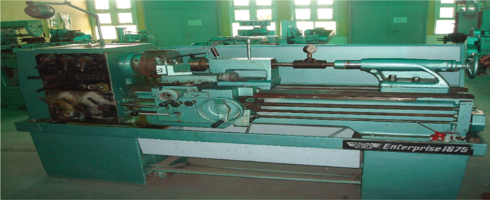
The macrograph shows the friction welding setup.
3. Mechanical Testing
Friction welded parts were subjected to variety of mechanical tests to determine their suitability for the anticipated service applications. They were necessary to carry out so as to ensure the quality, reliability, and strength of the welded joints. There are two methods of testing the quality of the friction welded joint: destructive testing and nondestructive testing. In our testing we follow the former type of testing and mechanical properties like tensile strength, impact strength, and microhardness were evaluated combined with the visual inspection which was the part of nondestructive testing. In the destructive testing generally the parts were damaged after the tests were over.
3.1. Tensile Test
Tensile test carried for this study was performed on the Universal Testing Machine made by HIECO having the capacity of 60 Tons. Firstly the standard specimens were prepared for this and for the ASTM standards were followed for making the sample. The gauge lengths of the specimens were maintained according to the ASTM A370-12 standards keeping the weld interface at the center of the gauge length. The sample was then fitted firmly between the jaws of the machine and load was applied. Corresponding to this load the value of stress at gradual intervals has been calculated out; simultaneously the change in length in relation to the applied load has also been monitored and the value of strain has been evaluated. This test was carried out on the friction welded samples of AISI 304 with AISI 1021 materials to measure their strength in tension. In this test the specimen was subjected to axial tensile load till its failure occurs.
3.2. Impact Test
This test was carried out on the pendulum type single blow impact testing machine so as to measure their notch impact toughness. Again the samples were prepared according to the ASTM standards maintaining the notch at the center of the weld interface. The specimens were supported at both ends as a simple supported beam and was broken by a falling pendulum on the face opposite to the notch and the energy absorbed by the specimen was noted down. For Izod test the specimens were vertically placed and the notch was facing the falling pendulum. For Charpy impact test the size of the specimen was kept as55 mm × 10 mm × 10 mm and the depth of the notch was kept as 5 mm deep and for Izod test the specimen dimensions were kept as 75 mm × 10 mm × 10 mm and the V notch was made 2 mm deep not in the center but 28 mm away from the striking end.
3.3. Microhardness
For microhardness testing Vickers hardness testing machine was used. Inthis test a square based pyramid type diamond indenter was used and the hardness variation on the weld interface as well as along with it, across the weld interface on both parent materials, was obtained by applying a constant load of 500 gf. The indentations were made at the weld interface and on both sides along the axis of the shaft at the regular intervals of 1 mm apart so as to find out the effect of heat on the hardness values.
4. Results and Discussion
4.1. Visual Examination
Figure 2 shows some of the friction welded specimens; the visual examination of the friction welded specimens exhibits flash during friction welding and it has been observed that the amount of flash increases with the increase in axial pressure. It has also been observed that higher flash was generated towards ferritic steel and the amount of flash towards austenitic stainless steel was very less suggesting that the deformation is mainly limited to ferritic steel side. Similar results have been reported by Satyanarayana et al. [2].

Shows the friction welded specimens.
4.2. Tensile Test
Tensile test was performed on Universal Testing Machine made by HEICO having a capacity of 60 T. In this test the specimens were subjected to axial tensile load till its fracture occurs. On the basis of the results obtained from the test, stress versus strain and load versus time taken before fracture graphs have been plotted. Table 2 shows the tensile strength results of the friction welded specimens. It has also been observed that the tensile strength obtained from the specimens varied from 381.76 MPa to 408.08 MPa; also it has been depicted from the values obtained experimentally that with the increase in the axial pressure the tensile strength goes on increasing and this may be attributed to the fact that with the increase in axial pressure more mass is thought to be transferred at the weld interface. Özdemir and Orhan [8] reported similar trends. During tensile testing all the joints failed at the weld joint but the elongation varied from 3.39 mm to a maximum of 8.52. The maximum elongation was achieved at 120 MPa axial pressure giving the maximum percentage elongation of 17.04% and showing relatively ductile behavior compared to the other specimens. Also it has been observed that the time taken before fracture varied from 13 to a maximum of 22 seconds.
Experimental values observed during tensile testing.
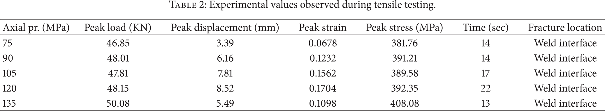
Figure 3 shows the variation between the stress and strain; from the Figure it has been observed that as we go on increasing the axial pressure the value of stress goes on increasing and the maximum value of stress was available at 135 MPa axial pressure. Figure 3 also depicts that the maximum strain was available at 120 Mpa axial pressure and on the same axial pressure the stress available was 392.35 MPa. Figure 4 depicts that the maximum time taken before the fracture was observed on 22 seconds and that too was obtained at 120 MPa axial pressure.

Shows the variation of stress versus strain at different axial pressures.
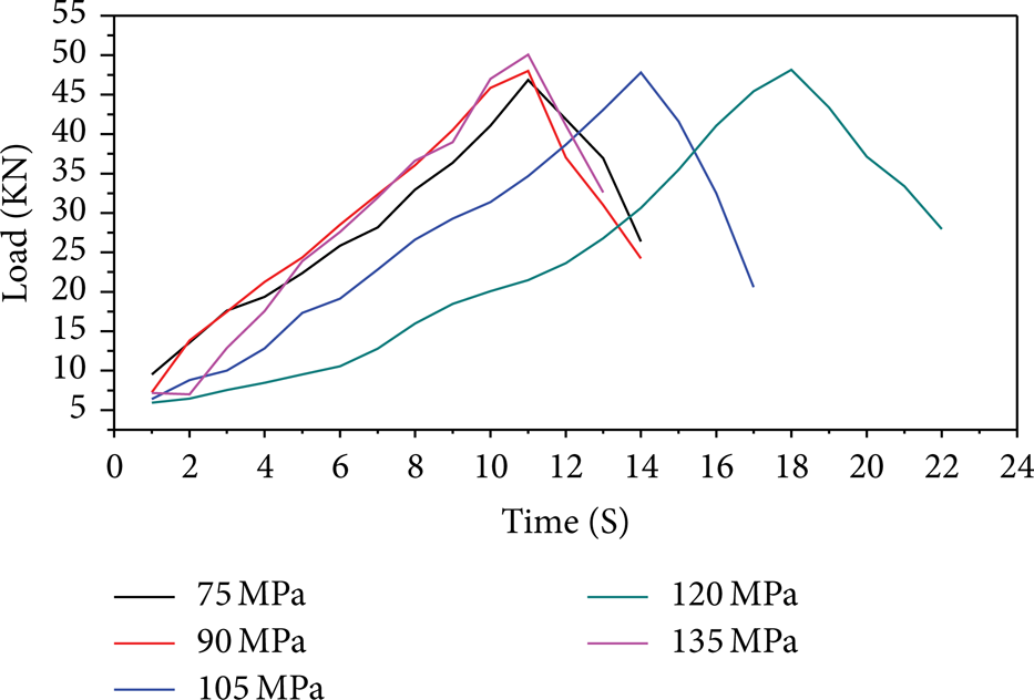
Shows the variation of load applied versus time taken before fracture at different axial pressures.
4.3. Impact Test
The notch impact toughness tests were carried out to find the amount of energy absorbed during fracture. Two types of tests were carried out, namely, the Charpy impact and Izod impact strength. The samples prepared for impact testing were according to ASTM standards A370-12. Both Charpy and Izod impact results in terms of fracture energies have been reported in the Table 3. As it can be seen from the table that the Charpy toughness of the welded parts is slightly larger than the Izod impact toughness, this may be the reason for the placement of the impact samples towards the impact load. Figure 5 reveals that the impact strength firstly increases with the increase in axial pressure, then remains constant up to 105 MPa pressure, and after that with the increase in axial pressure declines a bit. When the pressure increases beyond 120 MPa, there was steep decline in the impact strength. Figure 6 shows that the impact strength gradually starts declining with the increase in axial pressure up to 105 MPa. It raises a little bit at 120 MPa and then with the further increase in axial pressure it shows steep decline. In general it has been observed that the impact strength goes on decreasing with the increase in the axial pressures and if the axial pressure increased beyond 120 MPa there was immediate decline in strength observed. Similar results have been quoted by Satyanarayana et al. [2]. It has also been observed that with the increase in the axial pressure the flash increases, and experimentally it has been found that with the increase in the flash the impact strength decreases. Similar results have been quoted by Arivazhagan et al. [9, 10].
Experimental values observed during impact testing.


Shows the variation of Charpy impact strength versus axial pressure.

Shows the variation of Izod impact strength versus axial pressure.
4.4. Microhardness Test
The microhardness variations were obtained on Vickers hardness testing machine. The hardness variations at the weld interface and across the weld interface were obtained by applying a constant load of 500 gf and have been reported in Table 4. The hardness was measured at the weld interface and on either side of the parent materials. Figure 7 shows the hardness variations on both sides at a distance of 1 mm apart and the hardness was also measured at the weld interface. It has been observed from the plot that AISI 1021 shows less hardness than the AISI 304. This decrease in hardness may be attributed to recrystallization process taking place at the heat affected zone towards the low alloy steel. Ananthapadmanaban et al. [11] also found similar results. It has also been observed that the maximum hardness was obtained at the weld interface for all the joints as has been quoted by Özdemir and Orhan [8]. The peak hardness of friction welded joints increases with the increase in burnoff length as has been suggested by Arivazhagan et al. [10]; similarly our plot follows similar trends. It was observed that with the increase in burnoff length a soft region appears on the austenitic stainless steel adjacent to the weld interface. The formation of soft region can be attributed to decarburization. This may be caused by the presence of heat as the thermal conductivity of the material is relatively low as has been found by Satyanarayana et al. [2]. In addition to the fact that the higher values of hardness at the weld interface were probably due to the oxidation process which takes place during friction welding, similar trends have been reported by Ates et al. [12]. The higher hardness values were found to be at austenitic stainless steel side for all the samples.
Experimental values obtained during Vickers hardness test.


Shows the variation of hardness across the weld interface at different axial pressures.
5. Conclusions
The following conclusions are made from the study.
The axial pressure has been found to be an influential parameter for the friction welding process, which has been optimized for the process based upon the results of the present study. The mechanical properties of the friction welds were found to vary with the applied axial pressure, which indicates that axial pressure is an important welding parameter. The axial pressure could be successfully optimized for the friction welding process on the basis of the results of the current investigation.
The maximum tensile strength for welded bars was achieved with an applied axial pressure of 135 MPa, but the specimen fails in a brittle manner without giving any indication, whereas small amount of necking appears on the specimens which were prepared at an axial pressure of 120 MPa and the difference between the load carrying capacity with 135 MPa is marginal. This was attributed to the interfusion of carbon from the low alloy steel towards AISI 304 at very higher axial pressures; similar trends have been reported by Sahin [7].
It has also been found that maximum elongation of the welded specimen and maximum time taken before failure were observed at 120 MPa axial pressure.
It has also been observed that the impact strength for the weldments was also acceptable at 120 MPa axial pressure.
With the increase in the axial pressure the hardness at the center of weld cross-section increases. This was the result of the high heat generated and the immediate fall in temperature at high axial pressures in which austenite starts converting into martensite. The hardness results are in agreement with the results revealed by Arivazhagan et al. [9, 10].
Conflict of Interests
The authors declare that there is no conflict of interests regarding the publication of this paper.