
Abstract
Under rainfall conditions, rain-wind induced vibration occurs on high-voltage transmission line occasionally. This phenomenon is caused by raindrops hitting the high-voltage conductor with a certain velocity and suspends to the bottom surface of the high-voltage conductor. By action of wind velocity and high-voltage conductor's motion, some suspended raindrops will be blown away or shaken off. The remaining water may be reformed as upper rivulet and lower rivulet. Like the effect of icing galloping, this type of vibration can cause metal fatigue on fittings and towers, while its mechanism remains unknown. The objective of this paper is to validate an analytical model of rain-wind induced vibration of the high-voltage transmission line and to investigate the effect of wind velocity, rivulet motion, raindrop velocity, and time varying mass on the vibration amplitude. Taking Tuo-chang transmission line as an example, the analytical model is solved by Galerkin weighted residual method and central difference method. The numerical results are in agreement with the experimental data available in the literature. The analytical model enables more comprehensive understanding of the rain-wind induced vibration mechanism.
1. Introduction
The planned ultra-high-voltage transmission tower-lines will be across the terrain, wet, and rainy regions of southwest China; one of the key problems is how to ensure secure and stable operation of the high-voltage transmission tower-lines [1]. Under rain-wind conditions, raindrops hitting the high-voltage transmission line may form rivulets on the surface of the high-voltage conductor. The presence of the rivulets makes cross-section of the high-voltage conductor become asymmetric. Furthermore, the raindrops injected in or shaken off from the high-voltage conductor lead to the mass of whole system varies with time. The asymmetric cross-section of the high-voltage conductor, motion of the rivulets, and time varying-mass of the whole system maybe are the main cause of rain-wind induced vibration on high-voltage transmission lines. Like the effect of icing galloping, this phenomenon can result in fatigue fractures of high-voltage conductor and fatigue failures of spacers and insulators and threaten the safety and serviceability of the high-voltage transmission tower-lines [2–4]. However, it is difficult to explain this phenomenon by Den. Hartog theory.
For the purpose of revealing the mechanism, many attempts with field measurements, rain-wind tunnel tests, and theoretical analyses are conducted by researchers and engineers around the world. Farzaneh and Phan [5] and Farzaneh [6] carry out laboratory tests on smooth and stranded conductors with different type of supports and indicate that intermittent presence of space charge comes from hanging raindrops is responsible for the corona-induced vibration of the conductors. Liu [7] finds out that the vibration amplitude of the high-voltage conductor is obviously affected by whether the high-voltage conductor is powered on, with long-term field observation of Tuo-chang transmission lines in Hunan province. Li et al. [2, 8, 9] propose a calculation method for rain loading and study dynamic response of transmission tower-lines system with Kaimal spectra. The results show that rain loading coupling with wind force have a more distinct effect on dynamic characteristics of the high-voltage transmission tower-lines system than that of only acting by wind force, and rain loading plays an indispensable role in rain-wind induced vibration of the high-voltage conductor. Zhou et al. [3, 4, 10, 11] investigates the effects of ionic wind, rainfalls, wind velocity, and nonlinear cross-sections on the vibration amplitude of the high-voltage transmission line and emphasizes that raindrops hitting the high-voltage transmission lines may form a rivulet of which position varies with time. Moreover, ionic wind has a certain influence and is easily to couple with wind velocity. Additionally, the rain-wind induced vibration of cables in cable-stayed bridges is also a worldwide problem of great concern in the bridge and wind engineering communities for many years [12, 13]. In order to clarify the mechanism of this phenomenon, field measurements, wind tunnel simulation tests, and theoretical analyses are conducted by researchers and engineers around the world [14–16]. Nevertheless, the mechanism of rain-wind induced vibration of the high-voltage conductors or the cables remains unclear.
The above studies and the literatures about the rain-wind induced vibration are valuable and enable more comprehensive understanding of the formation mechanism of the rain-wind induced vibration of the high-voltage conductor. There are some obvious distinctions between the rain-wind induced vibration and the icing galloping and it must be emphasized that the position of the rivulet varies with time, the mass of whole system varies with raindrops injected in or shaken off, and the velocity of raindrop hitting the high-voltage conductors, whereas ice coating is just fixed to the surface of the high-voltage conductor. Very few works on the effects of rivulet motion, time-varying mass of whole system, raindrop velocity, and wind velocity for the mechanism of this vibration are carried out. For this reason, the main objective of the present work is to reveal the mechanism by developing a valid analytical model of rain-wind induced vibration of the high-voltage transmission line, which takes the variation of several factors such as rivulet's motion, time-varying mass of whole system, raindrop velocity, and wind velocity into account.
2. Analytical Model of Rain-Wind Induced Vibration on the High-Voltage Conductor
2.1. Basic Assumptions
The phenomenon of the high-voltage conductor vibration induced by rain and wind is very complex. To simplify the analysis, some feasible assumptions are made to establish the analytical model of rain-wind induced vibration of the high-voltage conductor:
the quasi-steady state assumption is valid;
the in-plane, small amplitude vibrations of the high-voltage conductor with a small sag;
upper rivulet has strong influence on aerodynamic characteristics of the high-voltage conductor, whereas the lower rivulet almost can be neglected;
the corona discharge and ionic wind will not be taken into consideration, only considering the effect of electric field strength on the shape of the upper rivulet;
the effect of bending, torsion, and shear stiffness of the high-voltage conductor is ignored in the following analysis.
2.2. Formation Mechanism of Rain-Wind Induced Vibration on the High-Voltage Conductor
The formation mechanism of rain-wind induced vibration on the high-voltage conductor can be summarized by the following steps (Figure 1) [3, 7, 11].
In the absence of rain-wind conditions, the high-voltage transmission line stays still at equilibrium position y = 0.
Under the condition of rainfall, the raindrops hit the high-voltage conductor with velocity v1 and remains on the bottom surface of the high-voltage conductor and will be blown away or shaken off after a period of time. So, the mass of raindrops attaching to the high-voltage conductor varies with time.
Under the condition of rain-wind, the remaining raindrops on the high-voltage transmission lines form upper rivulet and lower rivulet by acting of both wind and rain, and the upper rivulet position θ varies with time. Furthermore, the upper rivulet subjected to electric forces takes as a cone shape.

Formation mechanism of rain-wind vibration.
As analysis above shows that the shape of cross-section composes of the high-voltage conductor, the upper rivulet adheres to the high-voltage conductor, and wind velocity acts on the rivulet and on the momentary acceleration of the cross-section. Therefore, the formation mechanism of rain-wind vibration relates to many factors such as the raindrops, the wind velocity, the rivulets, and corona discharge.
2.3. Analytical Model
The vibrations of high-voltage transmission lines and cables of cable-stayed bridges with the rivulets on their surface are the cases of time-varying dynamic systems [17]. For those constructions, a damped, single degree of freedom continuous model with time-varying mass will be considered. Let us use elastic and uniformed cylinder with small-sag to represent the high-voltage conductor, sketch of a two-dimensional continuous high-voltage conductor and its cross-section with upper rivulet is shown in Figure 2. The inclination of the cylinder is denoted by angle β, and wind velocity is denoted by U perpendicular to the cylinder. Thus, the in-plane vertical motion of the high-voltage conductor subjected to a distributed external force can be represented by the following equation:
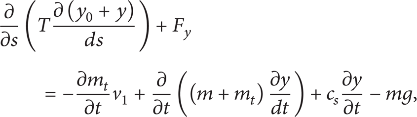
where m is total mass of the high-voltage conductor and the rivulets suspended to its surface per unit length and cs denote structural damping per unit length of the high-voltage conductor, respectively. y0, yh, and y denote a static deformed position, maxim sag at middle span, and dynamic displacement of high-voltage conductor, respectively. T is the tension force on the high-voltage conductor. The aerodynamic forces acting on the high-voltage conductor in the vertical direction are defined as F y . The time-varying mass of the raindrops that eject in or shake off from the high-voltage conductor is defined as mt, and m + m t denotes the total time-varying mass.
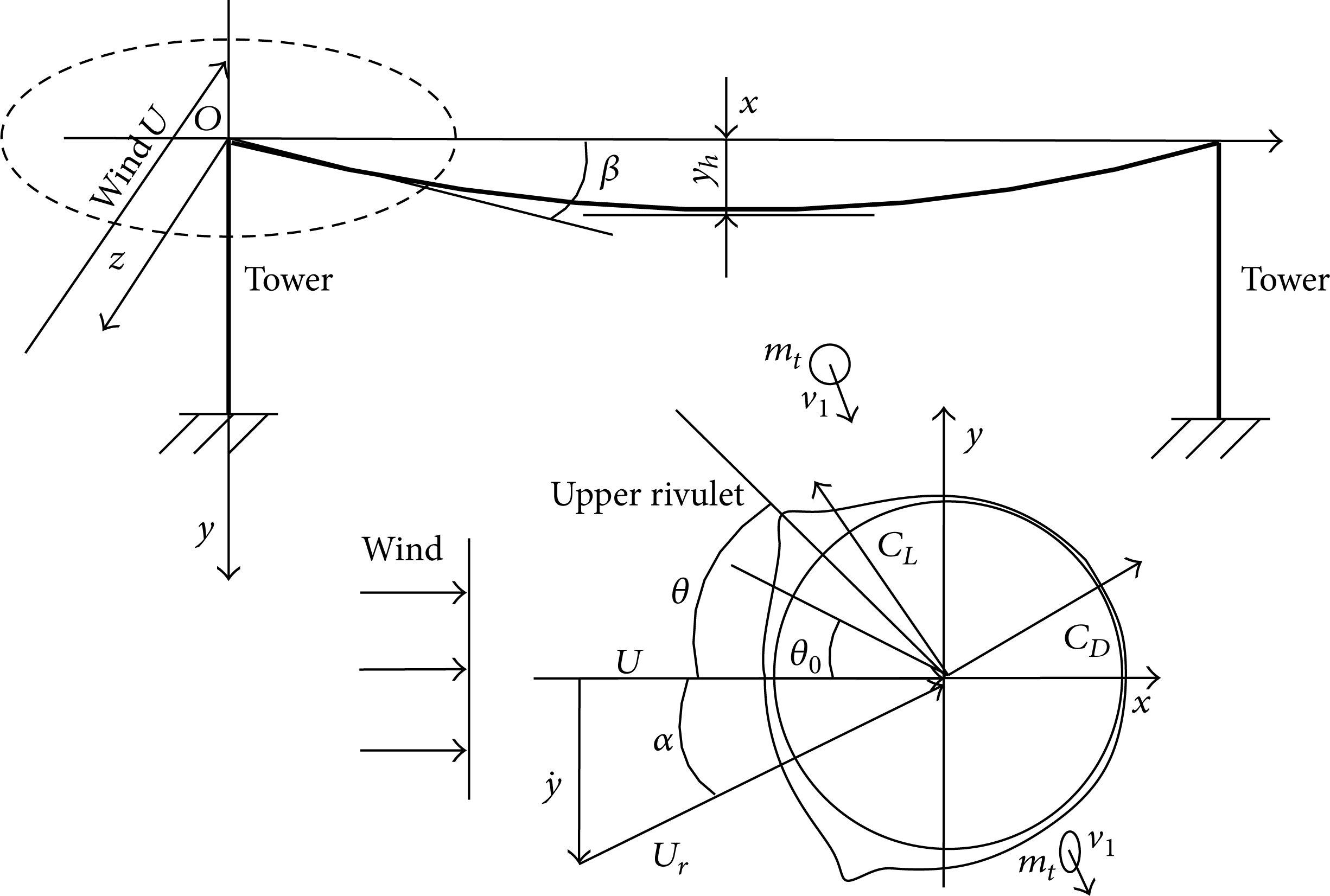
Sketch of high-voltage conductor and its cross-section with rivulets.
As a preliminary theoretical study, the upper rivulet is assumed to uniformly distribute along the longitudinal axis of the cylinder and circumferentially vibrate over the surface of the cylinder. As shows in Figure 2, the stable position of the upper rivulet is denoted by angle θ0, the dynamic position is represented by θ, the horizontal uniform wind velocity is denoted by U, and the angle of attack in the plane normal to the conductor is represented by α. The drag coefficient C
D
is indicated in the direction of the resultant wind velocity U
r
, whereas the lift coefficient C
L
is perpendicular to C
D
in anticlockwise direction. In consideration of the transverse vibration of the cylinder with velocity

Based on quasi-steady state assumption, F y acting on the high-voltage conductor can be expressed as

where φ = α + θ, and ρ denotes the mixed density of air with raindrops.
3. Solution of the Equation of Rain-Wind Induced Vibration on the High-Voltage Conductor
Assuming that tension force along the length direction of the high-voltage conductor is constant, tangential component of tension force can be derived with

where tangential component of T is H, and l is span of the high-voltage conductor.
The numerical simulations are performed taking as reference the experimental data cited in [18]; for an aluminum conductor steel reinforced conductor, 4 m in length, and 2.46 cm in diameter, the mass of the conductor per unit length is 0.96 kg. The conductor is subjected to artificial rain and wind from 2 m/s–25 m/s. The boundary conditions are defined as follows: the left side is the inlet of velocity and the flow velocity is uniform; the right side is the outflow and is a fully developed outlet boundary; the upper and lower boundaries are free-slip wall; and the conductor surface is wall. The SST k-ω turbulent model based on the RANS method is used to simulate the flow in the CFD numerical simulation. The fluid velocity of the conductor surface is equal to the conductor velocity. These results are in agreement with the experimental results, especially when ε = 0 and v1 = 0. Based on typical curves obtained from Figure 3, the aerodynamic drag and lift coefficient in (3) can be expressed as
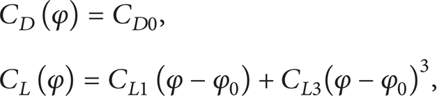
where CD0>0, CL1<0, CL3>0, and φ0>0. φ0 is any angle in the domain of the φ axis of the C L (φ) curve where the slope is negative, that is, CL1<0.
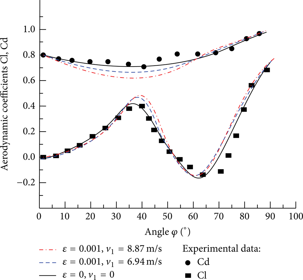
Aerodynamic coefficients versus angle φ.
In terms of modeling one may say that the mass flow of incoming raindrops hitting the high-voltage conductor and the mass flow of the raindrops shaken off will be arrhythmic, and nonuniformly distributed along the high-voltage conductor. Considering the variation of the quantity of raindrops maybe relevant for instability mechanism, and a new model for the study of rain-wind vibrations of a simple oscillator with time-varying mass is established, in which the mass of the water ridge is supposed to vary harmonically with time [17].
To simplify the analysis, in this section, we use the assumption as given in [17]. Therefore, we assume that time-varying mass mt is fluctuating with a positive value, and the frequency of which normally is an integer submultiple of excitation frequency [19]. Furthermore, based on the observations from either filed measurements or simulated wind-rain tunnel tests of the cables in cable-stayed bridges [12], the motion of the upper rivulet, θ, is assumed to be harmonic as long as the steady-state vibration. The frequency of the upper rivulet motion is almost the same as that of the high-voltage conductor; for this reason, we assume that the upper rivulet frequency is equal to that of the high-voltage conductor. Thus, the total time-varying mass and the dynamic position of the upper rivulet can be expressed as:
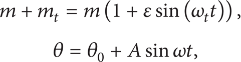
where ε = m t /m (0<ε ≪ 1) is the mass ratio, and which is a small parameter. ω a = ω/n (n is an integer) is the frequency of raindrops ejected in or shaken off from the rivulet, and A is the amplitude of the upper rivulet motion.
Substituting (5) and (6) into (4), the mono equation around

where c s = c/m and υ = H/m, and

As Figure 4 shows, the high-voltage conductor is divided into n units, and length of each unit is equal to h = l/n in the x-direction. The end nodes is numbered from 0 to n; other nodes are followed by 1, 2, 3, …, n–1. The boundary condition is defined as


Discretization of the high-voltage conductor in the x-direction.
Taking an approximate solution to each unit, the vertical displacement can be expressed as


Shape function of high-voltage conductor.
By Galerkin weighted residual method, substituting (9) and (10) into (7) leads to

where

After assembling all units,

Considering that the mass matrix and the damping matrix are functions with respect to t, (13) needs to be discretized by central difference method as

By solving (14), it is possible to find amplitudes, and then each
4. Numerical Computations and Discussion
To investigate the capability of the analytical model for revealing the rain-wind induced vibration mechanism, the numerical studies on the Tuo-chang transmission line are performed taking the experimental data cited in [4, 7, 20] as reference. The key parameters of the high-voltage transmission line are taken as diameter of 24.66 mm, mass per unit length of 0.96 kg/m, span of 255 m, elasticity coefficient of 73 kN/mm2, tension force of 8.31 kN, and mixed density of air and rain is assumed to be 1.3 kg/m3. By using ANALYS software, the natural frequency of dry high-voltage conductor can be easily calculated (Table 1).
Natural frequencies of the high-voltage conductor.

According to a large number of field observations, the range of raindrop's diameter D is 0.1 mm∼6 mm, and distributed exponentially with Marshall-Palmer spectral distribution [21]. n(D) = N0exp(–ΔD), where N0 = 8 × 10³ (m3/mm), gradient factor Δ = 4.1I−0.21 and I is the rainfall rate shown in Table 2.
The level of rainfall (unit: mm/h).

In a certain rainfall conditions, the volume occupancy ration of the different size raindrops is πD3n(D)/6. Consequently, time-varying mass mt can be derived as m t = πD3n(D)/6·ρ′·2Rl, where density of raindrops is ρ′ = 0.001 g/mm3. By calculating, we can obtain the mass ratio of ε ≈ 0.001, for rainfall rate of 8 mm/h∼32 mm/h. Verified with experimental data, the calculation formula [8] of raindrop velocity v1 for any altitude can be derived as

As the rivulets generally occur at rainfall rate of 8 mm/h∼32 mm/h, the raindrop diameter mainly is 1.0 mm<D<6.0 mm. In order to simplify the analysis, we only take value of the raindrop diameter of 2 mm and 4 mm to calculate the raindrop velocity. By calculating, the raindrop velocity of the diameter 2 mm is v1 = 6.94 m/s and the raindrop velocity of the diameter 4 mm is v1 = 8.87 m/s, respectively.
4.1. Fixed Upper Rivulet with Time-Varying Mass
To start with the simplest case, in this section, we investigate the dynamic behavior of the high-voltage conductor with fixed upper rivulet and time-varying mass by using the derived formulation. Once the upper rivulet is fixed, the dynamic motion θ(t) of the upper rivulet is equal to the stable position θ0. The equation of in-plane vertical motion of the high-voltage conductor can be rewritten as

Consequently, aerodynamic coefficients ca in above equation will be changed, and ca is expressed by ρRU((CD0 + CL1) + 3CL3(α + θ0 – φ0)2)/m which depends on the velocity
To better fit the curves of the drag and lift coefficients, two sets of data are used to express the values of CD0, CL1, and CL3 in (5) distinguished from the critical angle of φ ≈ 40°.
Figure 6 shows that amplitude of in-plane vertical vibration of the high-voltage conductor with the fixed upper rivulet at wind velocity U of 10 m/s, structural damping factor cs of 0.1%, and natural frequency of 0.69 Hz varies differently with the mass ratio ε and the raindrop velocity v1. Given a small initial motion, the vibration amplitude increases with time at the first 200's with ε = 0 and v1 = 0, the vibration amplitude increases with time at the first 190's with ε = 0.001 and v1 = 6.94 m/s, and the vibration amplitude increases with time at the first 180's with ε = 0.001 and v1 = 8.87 m/s. The reason for those is that the total damp ratio c
s
+ c
a
<0 during this period. As the vibration amplitude keeps increasing with time, the velocity

Amplitude of in-plane vertical vibration of the conductor with the fixed upper rivulet.
The total damping ratio c s + c a of the high-voltage varies differently with different mass ratio of ε (Figure 7). After the vibration amplitude increases to a certain level, the angel φ reaches to the value of 40° where the total damping ratio changes alternately from a negative value to a positive value. Due to this sudden change, the vibration of high-voltage conductor becomes almost periodic with nearly constant amplitude after a while (Figure 6).

Total damping ratio versus angle φ.
From the comparison of these curves (Figure 6), it can be concluded that the peak amplitude of the high-voltage at ε = 0 larger than that of the high-voltage at ε = 0.001, while after a longer time. On account of raindrop velocity v1, the high-voltage conductor with velocity v1 = 8.87 m/s reaches the peak amplitude faster than of the high-voltage conductor with velocity v1 = 6.94 m/s, and the high-voltage conductor with velocity v1 = 0 is the slowest one. These phenomena can be explained as the more mass of the high-voltage conductor, the more vibration amplitude. By introducing the raindrop velocity v1, it will contribute to the increasing of the vibration amplitude.
Wind velocity U modifies the vibration amplitude of the high-voltage conductor with fixed upper rivulet for different values of the mass ratio ε and the raindrop velocity v1, at the structural damping factor cs is 0.1% and the natural frequency of 0.69 Hz (Figure 8). The vibration amplitude of the high-voltage conductor increases almost linearly with the increasing of wind velocity U up to 13 m/s (when ε = 0 and v1 = 0), 11 m/s (when ε = 0.001 and v1 = 6.94 m/s), and 10 m/s (when ε = 0.001 and v1 = 8.87 m/s), respectively. Beyond this threshold, the value of vibration amplitude is nearly constant, no matter what the values of the mass ratio ε and the raindrop velocity v1. These results are in agreement with the experimental results [18], especially when ε = 0 and v1 = 0.

Amplitude of the high-voltage conductor in vertical direction versus wind velocity U.
This phenomenon somehow likes galloping vibration, but in fact it is found that the response amplitude is actually limited. The reason why the vibration amplitude is limited c
a
= ρRU((CD0 + CL1) + 3CL3(α + θ0 – φ0)2)/m depends on the velocity
When the wind velocity U is 0–12 m/s, the value of total damping ratio is negative and increases gradually. Once the wind velocity U reaches a certain level nearly 12 m/s, φ reaches its critical angle of 40°, at which the value of total damping ratio is zero. Furthermore, when wind velocity U exceeds 12 m/s, φ fluctuates around the critical angle of 40°, which makes the total damping ratio changes periodically within the range bounded by a positive value and a negative value (Figure 9). Different increasing rate of vibration amplitude and the critical velocity is due to the effect of ε and v1, by which the rain-wind vibration of the high-voltage conductor will be induced within a relatively small wind velocity U. So, the high-voltage conductor with fixed upper rivulet presents a velocity-restricted vibration response.
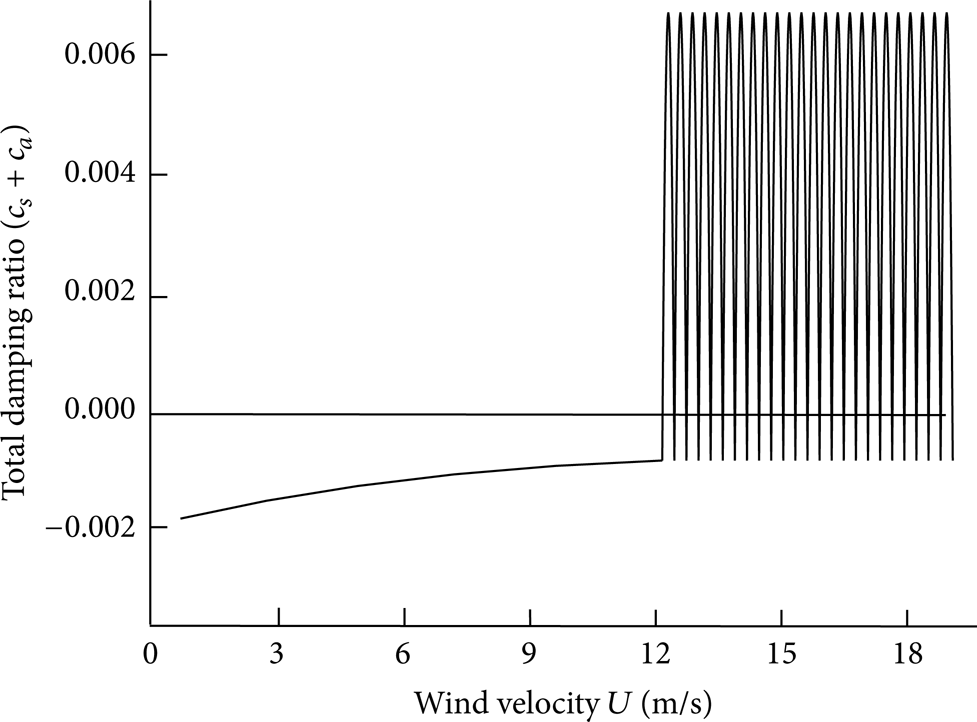
Total damping ratio versus wind velocity U.
4.2. Motion of Upper Rivulet with Time-Varying Mass
The upper rivulet is assumed to be fixed in Section 4.1, which is inconsistent with the actual operating conditions of the high-voltage conductor. To investigate the capability of the analytical model for predicting rain-wind induced vibration, this section investigates the dynamic behavior of the high-voltage conductor with motion of the upper rivulet and time-varying mass using the derived formulation and then compares the results with the experimental data. The numerical simulations are performed taking the experimental data cited in [18] as reference, for an aluminum conductor steel reinforced conductor, 4 m in length, and 2.46 cm in diameter, the mass of the conductor per unit length is 0.96 kg. The conductor is subjected to artificial rain and wind from 2 m/s–25 m/s.
The results obtained from the analytical model are shown in Figure 10, together with experimental data [18]. These results are in agreement with the experimental results, especially when ε = 0 and v1 = 0. It is seen that both of analytical and measured results demonstrate that static position θ0 is nearly a quadratic function of the wind velocity U, and the critical static position θ0 occurs within a certain range of wind velocity U. Once, out of this range, the static position θ0 gets a small value. This is because the aerodynamic forces F y get maximum value at this critical position, out of this position the force F y will decrease quickly. Different increasing rate of static position θ0 with the wind velocity U is due to the effect of ε and v1, by which the rain-wind vibration of the high-voltage conductor can be quickly activated within a relatively smaller wind velocity U.

Static position θ0 versus wind velocity U.
Correspondingly, as shown in Figure 11, both analytical and measured results indicate that the largest amplitude of the high-voltage conductor only occurs within a certain range of wind velocity U. Furthermore, out of the certain range of wind velocity U, the amplitude just gets a small value. This is because that only within a certain range of wind velocity U the aerodynamic forces F y get maximum value; out of this range the force F y decreases quickly.

Amplitude of the high-voltage conductor in vertical direction versus wind velocity U.
The vibration amplitude is due to negative aerodynamic total damping ratio, but its vibration amplitude will be eventually restricted because of the oscillation of φ around the critical angel leading the total damping ratio changes periodically within the range bounded by a positive value and a negative value. Because of φ = α + θ, the only way to avoid instability vibration of the conductor is making φ = α + θ far away from the critical angel, which means the wind velocity must be below or beyond a certain range of wind velocity.
5. Conclusions
For the aims of revealing mechanism of rain-wind induced vibration of high-voltage transmission lines, taking the raindrop velocity and time-varying mass into consideration, an analytical model for describing rain-wind induced vibration of high-voltage transmission line is introduced in this paper.
The analytical model is validated by comparing numerical results with the experimental data. The analytical model can capture main characteristics of rain-wind induced vibration on the high-voltage conductor with the fixed or moving upper rivulet.
Due to the value of total damping ratio changes alternating from negative to positive, the high-voltage conductor with fixed upper rivulet presents a velocity-restricted vibration response.
The largest amplitude of the high-voltage conductor only occurs within a certain range of wind velocity; out of this range the force F y will decrease quickly.
With the fixed upper rivulet, by introducing of the raindrop velocity v1, it will contribute to the increase of the vibration amplitude of the high-voltage conductor.
Different increasing rate of static position θ0 is due to the effect of ε and v1, by which the rain-wind vibration of the high-voltage conductor can be quickly motivated within a relatively smaller wind velocity U.
However, it should be noted that the proposed analytical model is still a preliminary model. The axial flow and turbulence effects are neglected in this paper. Further investigation should be carried out to develop a more realistic model by considering these effects.
Conflict of Interests
The authors declare that there is no conflict of interests regarding the publication of this paper.
Footnotes
Acknowledgments
The research presented in this paper is supported by the Natural Science Foundation of Youth Fund of China (no. 51205128) and the Fundamental Research Funds for the Central Universities (no. 2014ZD07).