
Abstract
In virtual cardiovascular surgery, the force feedback is transmitted via the flexible guide wire. In the force transmission, disturbance always occurs due to flexible deformation, and this would make it hard to ensure immersion by rendering the force feedback in actuator. As the effect of flexible deformation is related to the length of guide wire, experiment is designed to assess the force transmission of guide wire when the length between the actuator and operating point changes. In this paper, three indexes are proposed to search for the length between the actuator and the device entrance. And the optimal scope length of guide wire is found out to ensure the guide wire has the best performance for the force transmission.
1. Introduction
Virtual surgery is an efficient method to help novice surgeons to improve their surgical skills. Haptic force feedback and visual information supplied by virtual surgery training could help to reduce operative errors [1–3]. An excellent virtual surgery equipment should supply this thorough and continuous authentic feeling for trainees [4, 5].
Researchers have done a lot of work on the interaction of VR (virtual reality) and virtual surgery's haptic devices. Majority of works are focused on the establishment of virtual environment and the mechanical models of tissues. During the past decades, major advances have been achieved in the fields of computer graphics and its VR applications. Due to the developments of stereoscopic displays, virtual object, and material models, VR becomes a good simulation of surgery [6, 7].
Immersion feeling is the synthesis of haptic feedback. In VR training, virtual force models are established to give feedback force [8–11]. The VR simulator should provide the operator with the same feeling as real surgery [12–15], which is a sense of immersion by stimulus-response relation [16–18].
Cardiovascular surgery is a kind of complex surgery. The surgeon needs to skillfully operate the surgical instruments to reach the target place. One important skill for the surgeon is to avoid producing too much resistance force between the surgical instruments and the walls of vessels; otherwise the thin and delicate walls of vessels may be damaged by the intervention instruments. It requires doctors to take enough time to be trained.
In recent decades, the design of VR simulator of cardiovascular surgery has arisen interests of engineering. The VR simulator of Simantha is developed by the Medical Simulation Corporation in USA, in which the force feedback device is located in a patient model [19]. Simbionics company in America developed the ANGIO Mentor; it generates the friction between the eccentric wheel and surgical instrument as the feedback force [20]. The Mentice company in Switzerland developed the VR simulator of Mentice VIST; it enables the activation of force feedback through pressuring on surgical instruments [21]. Bailey used the spring piece to create force feedback in the VR training system [22].
In these simulators of cardiovascular surgery, a problem exists in which flexion deformation of the guide wire leads to disturbance of force feedback transmission [23, 24]. The response lag and force error caused by flexible deformation would make it hard to ensure immersion by rendering the force feedback in actuator [25–27].
Researchers use measurement experiments to acquire the force feedback in real surgery of invasive vascular intervention. Then the force rendered by the actuator is derived by the force transmission model from the measured force of intervention instruments [28, 29]. There were several methods to model the intervention instruments, such as model of elastic rod [23, 25] and energy optimization model [30].
Previous researches concentrate on the development of virtual surgery system and force transmission model of intervention instruments. However, the flexible deformation is related to the length of guide wire between actuator and the operating point of human hand. The length between the actuator and the device entrance can be optimized to keep the length of guide wire within a scope which has a better immersion sense of force feedback. In this study, experiment is done to assess the performance of force transmission when the length of guide wire between actuator and operating point of human hand changes [31–33]. The scope with the best dynamic performance of the guide wire can be found out through experiment analysis.
The rest of the paper is organized as follows. In Section 2, the design force feedback device of virtual cardiovascular surgery is described. Section 3 analyzes the effect of flexible deformation existing in the virtual surgery. Section 4 describes the experiment design for the optimization. In Section 5 the experiment is adopted and the experiment data is used to search for the best length of guide wire between actuator and the operating point. Finally, the conclusion is drawn in Section 6.
2. Force Feedback Device of Virtual Cardiovascular Surgery
Cardiovascular surgery is to treat the stenosis or blockage of cardiovascular system [34]. Surgeons need to control the motion of guide wire, balloon catheter, thick guide wire, and guide catheter in cardiovascular system under the navigation of real-time medical imaging and force feedback in the surgery process, as shown in Figure 1 (the figure is adapted and redrawn [24]).

Cardiovascular surgery.
There are several branches along the path of the vascular vessels. When the guide wire is moving in the vascular vessels, it would be under multipoint contact with the vessel in the fork route junction, which may render force feedback about 0.4 N-0.5 N. The force feedback of multipoint contact is larger than other situations of contact.
Once the force feedback is transmitted to human hand, the fingers of the operator have to disengage the guide wire and go back. Research reveals that a clear force change needs be given in the force turning point in virtual surgery training [35]. It can enhance the users feeling of model change and gives the users a better sense of immersion.
2.1. The Medical Instruments in Cardiovascular Surgery
2.1.1. Force Feedback Device
The VR simulator designed by our research group is shown in Figure 2. It renders image information by the computer, and the force feedback is given by a device. Novice surgeons could be trained through the virtual surgery by the image and force feedback. The VR simulator designed by our research group is shown in Figure 3.

The VR simulator of cardiovascular surgery.
Structure of the force feedback device.
The surgical instruments move in two degrees of freedom (DOF) (the forward movement and its rotation), and the force feedback in each DOF is essentially independent of each other [20, 21].
The resistance of the cardiovascular in real surgery is regarded as the virtual environment. It is a displacement-force relationship stored [33]. The VR training requires the force feedback (which is created by the force feedback device) the same as the real surgery [36, 37].
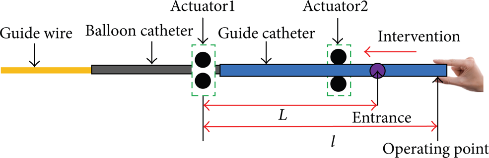
The force feedback is generated by the actuators and it is sent to the users via the surgical instruments. Actuator1 is the actuator which creates the force feedback of the guide wire. It is the farthest one from the operating point [19, 20].
As shown in Figure 3, the thick guide wire intervenes to the device first, and Actuator2 renders its force feedback. The guide catheter would intervene by the guide of the thick guide wire. They will all be stopped at the position of Actuator1. Then the thick guide wire will be disengaged and the guide catheter is used as the passage of guide wire and the balloon catheter. Actuator1 is used to render the force feedback of guide wire and the balloon catheter.
l is the length of guide wire between Actuator1 and operating point. L is the length of guide wire between Actuator1 and the device entrance. In the intervening process, the operator's hand moves to the device entrance and L varies. Its variation scope is about 0–4 cm. It is the length of guide wire between the operating point and the device entrance l − L. However, when the intervening is in the fork route junction of the vessel, the variation scope would be smaller as the surgeon would pay more attention. The length between Actuator1 and operating point should be 16 cm at least because of the hardware.
3. Flexible Deformation of the Guide Wire
In cardiovascular surgery, the guide wire may bend in the vessel and the stored energy of flexion deformation would lead to disturbance to the force transmission of the guide wire. The response lag and force error caused by flexible deformation would make it hard to ensure immersion by rendering the force feedback in actuator. The force status of the guide wire with flexible deformation is shown in Figure 4.

Force status of the guide wire.
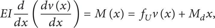
As shown in Figure 4, v is the deflection of the guide wire. f U is the force given by the actuator. f I is the feedback force felt by human hand which could be measured by force sensor. B is the point where the force feedback is rendered. A is the operating point of the human hand. l is the length of guide wire between the actuator and operating point. The energy stored by the bending is as follows [38]:

where x is the distance from the location A in the guide wire. E and I are separately elastic modulus and moment of inertia of the guide wire. The dynamical equation is as follows:
where v is the deflection of the guide wire and M d is the bending moment of the guide wire in the movement. Consider

The solution of (2) is as follows:

The Lagrange equation is shown as follows:
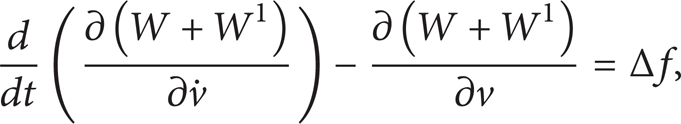
where W1 is the kinetic energy of the guide wire. Δf is the force transmission error caused by the flexion deformation of the guide wire. Consider

The kinetic energy W1 hardly change as v changes and (5) can be modified as

From (1) and (2), it can be seen that W has no relationship with

It can be attained that
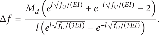
And it can be rewritten as

In (10), it can be seen that the flexible deformation would cause force feedback transmission error. The bending moment M d can be regarded as a random variable, as the angel and amplitude of force at point B (seen in Figure 6) is uncertain. And there are other influence factors of the transmission error, such as the natural bending of the guide wire.
If there is only one segment of flexible deformation as shown in Figure 4, it is obvious that the flexible deformation would decrease as the length of guide wire decreases. However, the guide wire is usually multiple segments of flexible deformation in the vessel or passage of force feedback device [23, 25], as shown in Figure 5.

The guide wire in the passage of force feedback device.

Guide wire in the glass of cardiovascular.
The guide wire is usually a discrete framed curve. It consists of a centerline comprised of vertices x1, …, x n and straight edges e1, …, en − 1. The energy stored by the flexible deformation is shown [25]:

where l i is the length of each segment of the guide wire, α is the bending modulus, and (kb) i is curvature binormal shown as follows:

Equation (11) reveals the total bending energy is the sum of the bending energy of each segment. Then the force transmission function of the guide wire is the multiplication of each segment's transmission function. However, the length of each segment and the number of segments would vary as the length of guide wire varies. When one segment is dissipating energy, the force transmitted to human hand would be larger, and when one segment is storing energy, the force transmitted to human hand would be smaller[26].
When the length of guide wire is longer and with more segment, the situation will be more complex. In the process of sudden force change, there may be one segment dissipating energy and the other segment storing energy; they may offset each other's effect to the force transmission. However, when the length of guide wire is shorter and with less segment, the situation of offsetting between each segment would be less.
The dynamic performance of the force transmission function of the guide wire may not constantly decrease as the length of guide wire increases. Then an experiment is designed to assess the dynamic performance of the guide wire when its length changes.
4. Experiment Design for the Optimization
4.1. The Guide Wire in Vessel
To model the force status of the guide wire in the vessel, a glass of cardiovascular system is used to simulate the cardiovascular system. As the glass is transparent, we can watch the moving process of the guide wire in the glass of cardiovascular as shown in Figure 6.
In this study, the force is rendered by the contact between the guide wire and the vessel wall. It can avoid the effect of the dynamical performance of the actuator, and the force transmission performance of guide wire will be shown directly. In Figure 6, the guide wire contacts with the vessel at one point, the force feedback will be transmited to human hand via the guide wire. However, multipoint contact may occur in fork route junction, as shown in Figure 7.

Guide wire in the glass of cardiovascular system when they are contacted with each other at two points.
As the guide wire is flexible, when the operator manipulates the guide wire to navigate in the vessel [23], the contacts may happen in several points; see the force F1 and F2 in Figure 7. It is the same as the real cardiovascular surgery. All these contacts will contribute to the force feeling on operator's hand [39].
The contact points of the guide wire with the vessel are uncertain when the guide wire is moving in the vessel. They may occur along the whole body of the guide wire; it is difficult to embed miniature force sensors into the body of the guide wire. However, the guide wire can only give one dimensional force feedback after the force transmission, while force feedback in other dimensions contributes to the flexible deformation.
The contact force F1 and F2 in fork route junction will contribute to the force feedback felt by human hand. The force transmission process of the guide wire is shown in Figure 8.

Guide wire in the glass of cardiovascular system.
As shown in Figure 8, A is the operating point of human hand, and B is the point of contact force F1. l is the length of guide wire between A and B. In the DOF of forward movement (the direction of f I in Figure 8), the force feedback rendered by the contact between vessel and the guide wire is shown:

where α1 denotes the angle between F1 and f I (the force feedback felt by human hand) and α2 denotes the angle between F2 and f I . The bending moment of the guide wire in the movement in (10) is shown:

where l1 is the distance between F1 and F2 and l is the length of guide wire between F1 and the operating point of human hand. Then (14) can be rewritten as

It can be seen from (15) that M d increases as l increases.
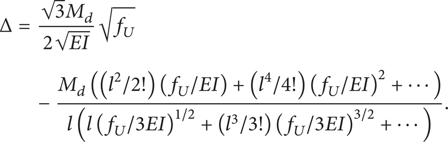
Equation (10) can be simplified by infinite series:

Equation (16) can be rewritten as

where Δ is shown as follows:
From (15) and (17), it can be attained that

Equation (19) can be rewritten as
where

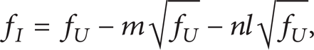
When the guide wire has the contact force F1, F2⋯F n , all of the forces contribute to the force feeling of human hand. Then m and n in (19) will be modified as
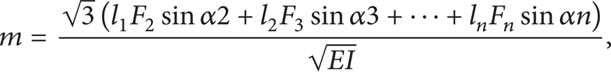

The parameters α2, α2, …, α3 depend on the structure of the vessel wall. As shown in (19), when l increases, the error between f I and f U would be larger if other parameters do not change. However, when the length of guide wire is longer and with more segment, force transmission of the guide wire will be more complex as the multisegment flexible deformation (as is discussed in Section 3).
4.2. Force Feedback Measurement
The amplitude and direction of force feedback are not the same every time the guide wire intervenes in the blood vessel. It can be seen from (19) that f I would be affected more by flexible deformation when l increases. In this study, experiment is designed to assess the relationship between f I and l. The measurement device is shown in Figure 9.

The force feedback measurement device.
In the force transmission process, the force feedback is rendered by the contract between guide wire and the vessel, and then it is transmitted to human hand. A sensor would measure the force feedback at the operating point of human hand.
The guide wire is 0.5~2 mm in diameter; the system should allow guide wire to move as the surgeons mode, including axial push-pull motions and twisting of the guide wire. The contact force is so small that the measurement system needs to provide high force accuracy [40]. Since the translational range of a measurement is usually small, a linear guide is used to coordinate the motion of the guide wire. The force measurement is shown in Figure 10.

Measurement of the force sensor.
The sensor is hollow and the guide wire can get through it. The sampling period of the force sensor is 0.25 ms and the resolution is about 0.004 N. The measurement range 0~20 N. Clamping and disengaging the guide wire are two operation modes with the load side of the sensor.
When the guide wire is clamped at the load side of the sensor, the contact force will be transmitted to human hand. Thus in the experiment, when the guide wire encounters the vessel wall, the contact force will be measured by the sensor in real time.
Once the guide wire is moved close to the vessel and the force feedback is transmitted to human hand, the fingers of the operator have to disengage the guide wire and go back. The guide wire will be disengaged from the load side of the sensor.
5. Experiment and Analysis
As discussed above, flexible deformation of guide wire is related to the length of guide wire between actuator and the operating point. Equation (16) reveals that the flexible deformation is related to the bending moment of the guide wire. The bending moment is related to the length of guide wire between Actuator1 and the operating point.
As the flexible deformation is complex because of multisegments' bending. In this study, experiment is designed to assess the dynamic performance of the guide wire when its length changes.
5.1. Experiment
In the experiment, the operator moves the guide wire from the big vessel (which simulates the aorta) to the small vessel (which simulates coronary artery). When the guide wire moves to the fork route junction, the multipoint contact occurs and then the force feedback begins to increase. The sensor measures the force feedback in real time.
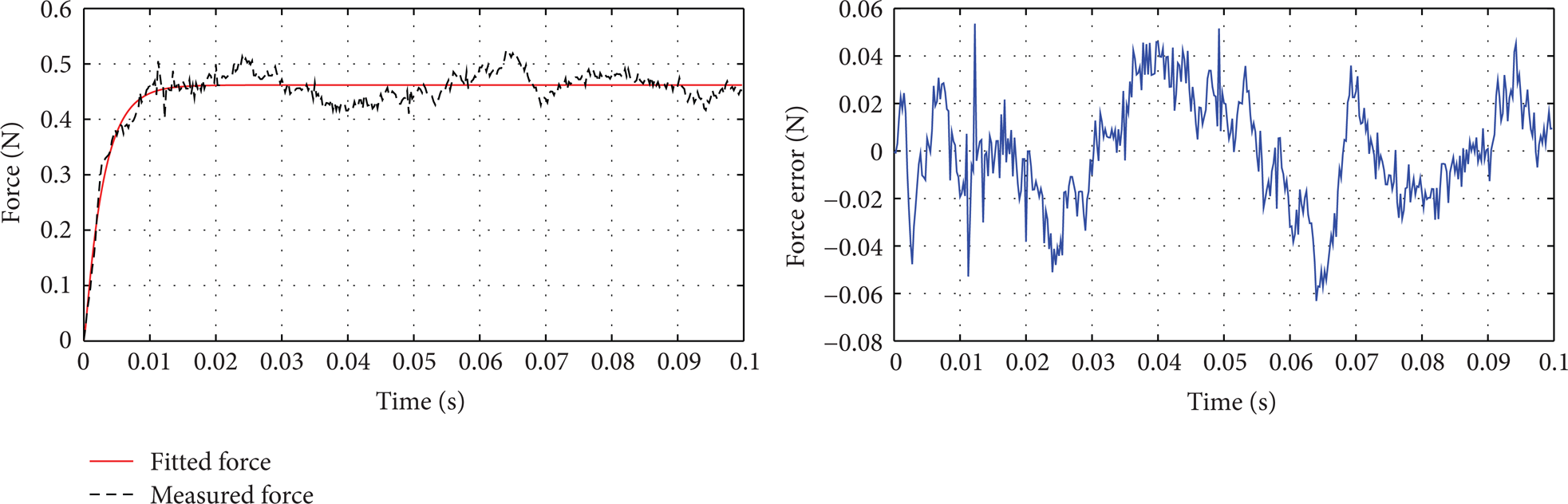
As the random factors in experiment would prevent us from getting the real force transmission model, the fitting of experiment force can be used to attain the ideal force transmission model. In this study, the ARX (auto regressive with exogenous input) model is adopted to do the fitting. A nonlinear ARX model has this structure:

where A(q− 1) and B(q− 1) are structure parameters of system model and q − 1 is lag operator. And n k is system lag and e(k) is a random white noise with mean zero. Consider

where n a and n b are separate orders of A(q− 1) and B(q− 1). This structure implies that the current output y(k) is predicted as a weighted sum of past output values and current and past input values.
In the fitting, the input is the steady-state of the force response process, and the output is the measured force. Based on the input and output of the system, the parameter of A(q− 1) and B(q− 1) can be attained by the system identification tool of matlab. The ARX model has the advantage of relatively simple structure and lower requirement for the experimental data. The model is fit for system with uncertainty and imprecision.
In the study, the order of A(q− 1) and B(q− 1) and n a and n b are all equal to 4. The parameter of ARX model is attained by the least squares method.
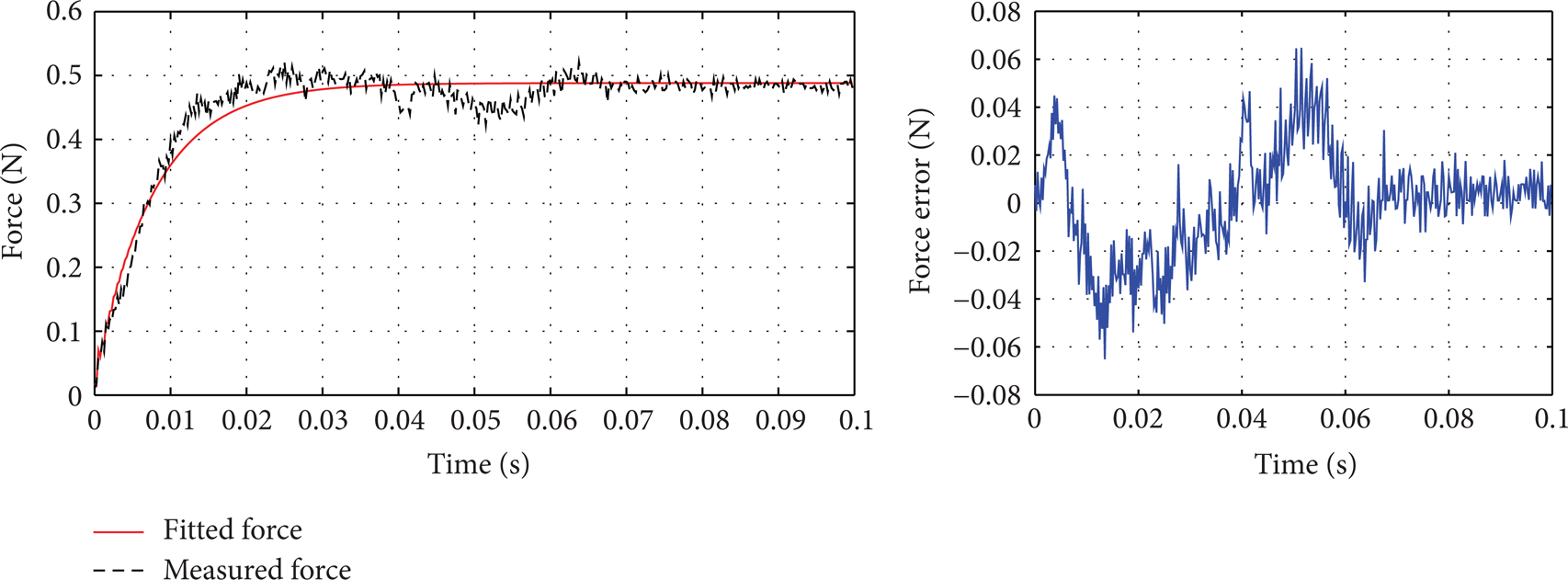
As shown in (13) in Section 4.1, the disturbance caused by flexion deformation is related to the the length of guide wire between the actuator and the operating point. The force transmission performance of five different lengths of guide wire are shown in the Figures 11, 12, 13, 14, and 15.

Force feedback when the guide wire between the actuator and operating point is 38 cm.

Force feedback when the guide wire between the actuator and operating point is 34 cm.

Force feedback when the guide wire between the actuator and operating point is 30 cm.

Force feedback when the guide wire between the actuator and operating point is 24 cm.
Force feedback when the guide wire between the actuator and operating point is 22 cm.
As shown from Figures 11 to 15, when the length of guide wire between Actuator1 and the operating point is reduced from 38 cm to 22 cm, the response time decreases as the length of guide wire decreases. When the guide wire between actuator and the operating point is 38 cm, the response time of the force change is the longest and the maximum error between the measurement force and fitted force is the largest. When the guide wire between force feedback and the operating point is 22 cm, the response time of the force change is the shortest, and the maximum error between the measurement force and fitted force is the smallest. And the variance between the measurement force and fitted force is even diminished as the length of guide wire gets shorter.
It can be seen that between the length of 38 cm to 22 cm, the force transmission performance is better when the length of guide wire decreases. However, the situation is not the same when the length of guide wire continues to decrease. The length of guide wire is reducing from 20 cm to 16 cm, as shown in Figures 16, 17, and 18.

Force feedback when the guide wire between the actuator and operating point is 20 cm.
Force feedback when the guide wire between the actuator and operating point is 18 cm.

Force feedback when the guide wire between the actuator and operating point is 16 cm.
Compare those figures to Figures 15 to 18; the response time, maximum error, and the variance do not decrease as the length of guide wire decreases and sometimes increase as length of guide wire increases. It reveals that when the guide wire is below 22 cm, the effect of flexible deformation may not decrease constantly as length of guide wire decreases.
5.2. Analysis and Discussion
Research reveals that when the force is smaller than 0.5 N, the perceptual resolution of discrimination threshold is 15–27% [41]. In this study, three indexes are introduced to assess the force transmission performance of the guide wire.
(1) The response time: the discrimination threshold defined as the moment force reaches 85% of the steady force, as 15% force error can not be sensed by human hand [41].
(2) The maximum error between the measurement force and the fitted force: as the amplitude of force feedback in those experiments is 0.4–0.5 N, the resolution of discrimination threshold is 0.075 N.
(3) The variance between the measurement force and the fitted force [42].
The response time of the force change, maximum error, and the variance are shown in Figures 19, 20, and 21.

The response time of different length of guide wire.
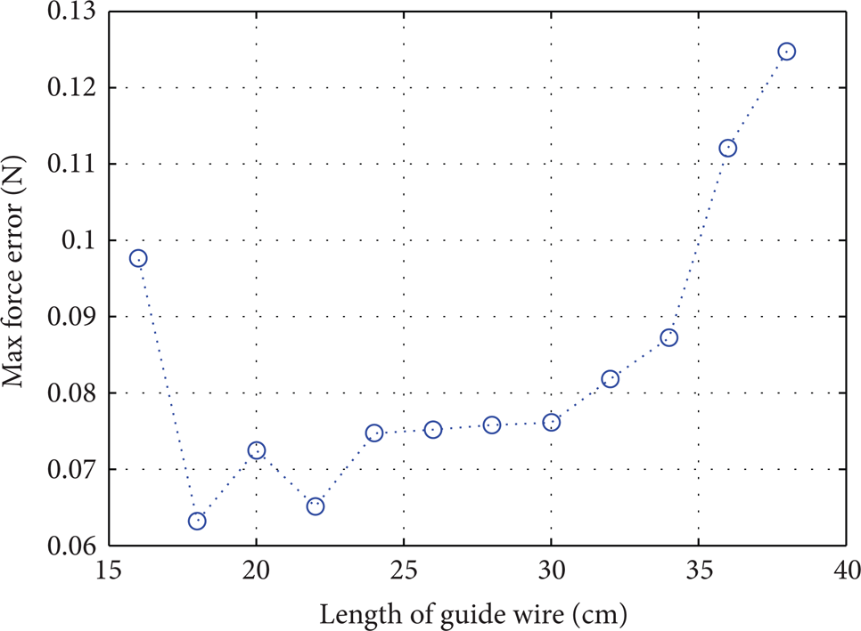
The maximum force error of different length of guide wire.

The variance of different length of guide wire.
Figures 19–21 show when the length of guide wire is within the scope of 24 cm–38 cm, the response times all exceed the force discrimination threshold 0.025 s, and the maximum force errors are all above the force discrimination threshold 0.075 N. It needs to be noted that the maximum and the variance all increase as the length of guide wire increases, while the response time sometime does not always decrease as the length of guide wire decreases. It is related to the complex of multisegments bending.
As it is studied in Section 3, when the length of guide wire is longer and with more segment, the situation of flexible deformation will be more complex. There may be offset of dissipating and storing in different segment. The response time does not always increase as the length of guide wire increases.
When the length of guide wire is within the scope of 16 cm–22 cm, the response time is below 0.025 s, and the maximum force error is below 0.075 N. The maximum force error is below the force discrimination threshold [41]. It means the users can feel force feedback of full immersion when the length of guide wire is within the scope of 16 cm–22 cm.
Within the scope of 16 cm–22 cm, the response time is smallest when the length of guide wire is 20 cm, while the maximum force error is smallest when the length of guide wire is 18 cm, and the length for the smallest variance is 20 cm. When the length is 16 cm, the three indices are not the smallest ones.
As it is mentioned in Section 2 the length of guide wire between the operating point and the device entrance has the variation of about 0–4 cm. And when the intervening is in the fork route junction of the vessel, the variation would be smaller, below 3 cm. When the length of guide wire is 16 cm, the three indices is not better than that of the length of guide wire between 18 cm and 20 cm. Then the optimized length between Actuator1 and the device entrance is found out as 18–20 cm. When using the optimized length to design the force feedback device, the length of guide wire between Actuator1 and the operating point will be in the range of better force transmission performance. Even the length between Actuator1 and the operating point varies to 22 cm and the three indexes are still below the threshold.
6. Conclusion and Future Work
In this study, the flexible deformation of the guide wire in the force feedback device of virtual cardiovascular surgery is analyzed. The research aims to find the optimized length of guide wire which has the response time below the human reaction time, and the maximum error below force discrimination threshold, and smaller variance. The optimized length of guide wire found out in Section 5 can be regarded as a guidance for design of force feedback device of virtual cardiovascular surgery. The optimized length gives a force transmission function of guide wire with better performance. And the force feedback device will give a better immersion sense of virtual surgery.
The study focuses on the flexible deformation of the guide wire, other intervention instruments, such as the guide catheter and balloon catheter, which can be optimized by the same way.
Though we have to find the best length of guide wire for the design of force feedback device, the training efficiency needs to be proved in practice. In the future work, we will use the VR training to optimize the device.
Conflict of Interests
The authors declare that there is no conflict of interests regarding the publication of this paper.
Footnotes
Acknowledgments
This research is supported by Key Program of National Science and Technology supported Program of China (2009BAI71B06) and Key Project of Chinese National Science Foundation (61190124). The authors would like to acknowledge the support provided by Peng Qin and Le Xie, Shanghai Jiao Tong University, Shanghai, China.