
Abstract
In order to improve combustion characteristic of swirl chamber diesel engine, a simulation model about a traditional cylindrical flat-bottom swirl chamber turbulent combustion diesel engine was established within the timeframe of the piston motion from the bottom dead centre (BDC) to the top dead centre (TDC) with the fluent dynamic mesh technique and flow field vector of gas in swirl chamber and cylinder; the pressure variation and temperature variation were obtained and a new type of swirl chamber structure was proposed. The results reveal that the piston will move from BDC; air in the cylinder is compressed into the swirl chamber by the piston to develop a swirl inside the chamber, with the ongoing of compression; the pressure and temperature are also rising gradually. Under this condition, the demand of diesel oil mixing and combusting will be better satisfied. Moreover, the new structure will no longer forma small fluid retention zone at the lower end outside the chamber and will be more beneficial to the mixing of fuel oil and air, which has presented a new idea and theoretical foundation for the design and optimization of swirl chamber structure and is thus of good significance of guiding in this regard.
1. Introduction
Swirl-chamber type diesel engine, especially the medium and low-power one, is now manufactured in large volume and widely used in China. In comparison with the direct injection diesel, swirl-chamber type diesel engine is more advantageous with simple air intake system and oil feed system, easy organization of working process, insensitivity to fuel quality atomization quality, high air utilization within the wider range of speed, less fault in oil feed system, good dynamic performance and high speed performance, high reliability, low noise, less emission of hazards, easy operation and maintenance, and convenience for service in the vast rural areas, and it is suitable for China's industrial level and user's usage level, in particular [1, 2]. The diesel's combustion process has been a key point of in-cylinder study all the time, while the formation and combustion of gas mixture and the structure of combustor are closely related to the motion of air therein [3]; a suitable swirling strength is available for effectively improving fuel evaporation, promoting the mixing progress of fuel and air [4–6], and thus improving the combusting condition inside the combustor. The recent years have witnessed people's coming to realize that the air's turbulent motion has played a critical role in the formation and combustion of gas mixture as well [7–9] and their progressive study on swirl-chamber type diesel engine. In the studies on swirl chamber, in other countries, Komatsu et al. have conducted simulation analysis on the flow field in the chamber [10] and Montorsi et al. and Okazaki et al. have studied the law on change of flow field in the chamber and oil atomization with the crank angle [11, 12]; in China, Zhu et al. have studied the influence of various interface channels on the flow field in the chamber taking the high-speed photography and numerical simulation method in succession [13, 14], Tang et al. have simulated the influence of interface channels in various angles of inclination on the flow field in the chamber [15], and An has conducted simulation analysis on the compression and atomization processes in the chamber [16].
In the compression stroke of swirl-chamber type diesel engine, the pocket of oil will enter into the swirl chamber with the upstroke of piston; the existence of turbulent flow and the guidance of wall face will result in air motion in all directions, thus complicating the air motion in the chamber, and have a direct effect upon the concentration of gas mixture in the hot space; therefore, the flow field distribution and combusting condition in the chamber is of vital importance to the engine's cold-start performance and emission performance. This paper studied the flow field characteristic in the swirl chamber of a certain type of swirl-chamber turbulent-combustion diesel engine with a fluid simulation software, presented the air flow status in the chamber and the change of gas velocity, pressure, and temperature in the swirl chamber and the combustor in the time frame of the piston's motion from BDC to TDC, and further proposed a new swirl structure.
2. Modelling and Meshing
2.1. Physical Model
The design in this paper takes a small-size single-cylinder air-cooled four-stroke diesel engine (S195) as the object of study; specific structural parameters and operating conditions are detailed in Table 1.
Simulation parameters of diesel engine.

Figure 1 is the sectional geometric figure of swirl-chamber turbulent combustor at the moment of piston's travelling to TDC, where Compression Volume V c is divided into to two portions: (1) the swirl chamber, on the cylinder head, the upper half is in the hemispheric shape and the lower half is in the cylindrical shape, in Volume V k ; (2) the main combustor, between the cylinder head and the piston top, both of which are connected via porous channel a and b. In operation, the fuel oil is ejected from the fuel injector nozzle in the swirl chamber along the swirl direction. In the process of compression, the piston will compress air into the swirl chamber via the porous channel to develop intensive vortex motion and promote the mixing of oil mist sprayed into the chamber. Once the pressure has risen to a certain extent, the gas mixture in the chamber will be combusted preliminarily to make the pressure and temperature rise sharply in the chamber; then the unburned gas mixture, fuel oil, and air will be compressed in the form of multistream cross-flow to the main combustor via Porous Channel to form a secondary vortex for further mixed firing.

As the structure of swirl chamber is not very complex, modelling and meshing are completed in gambit; as shown in Figure 2, Tetrahedral Mesh is used for the swirl chamber, channel, starting hole, and part of main combustor, of course, in consideration of the influence of geometric structure and meshing density on the calculated result; meshes of channel, starting hole, and upper part of main combustor are densified to different extents; hexahedral mesh is used for cylinder. As shown in Figure 3, due to the consideration of using dynamic mesh and the fact that large deformed region is very large, overlay and local remeshing method is used in the calculation of dynamic mesh.

Geometric model of swirl chamber combustion system.

Meshing of swirl chamber combustion system.
2.2. Mathematic Model
The control equation herein can be expressed as follows.
Continuous equation
where ρ is the fluid density, expressed in kg·m−3, and u is the flow rate, expressed in m·s−1.
Momentum equation

where p is the gas pressure, expressed in Pa: A0 is 0 in the calculation of laminar flow and is 1 in the calculation of turbulent flow; α is the dimensionless number, which varies with time; k is the kinetic energy of turbulent fluctuation, expressed in J; g is the specific volume force, which is a constant; and σ is the surface tension, expressed in N/m.
Energy equation

where T is the gas temperature, expressed in K; hm is the enthalpy of Constituent m, expressed in kJ; CP is the specific heat at constant pressure, expressed in kJ·(kg·K)−1; J is the thermal flux vector, which is the sum of thermal conduction and enthalpy diffusion; K is thermal conductivity; and Pr t is Prandtl Constant.
2.3. Dynamic Mesh Flow Field Calculation Equation
The conservativeness equation of general scalar ϕ on any control volume V with boundary moving can be depicted as follows:
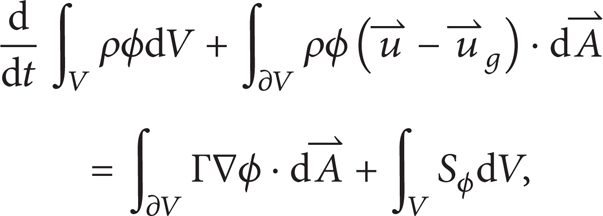
where V(t) is the control volume in the space, size and shape of which vary with time, and ∂V(t) is the moving boundary of control volume;
The time derivative in (4) can be obtained with the first-order backward difference formula:

where superscripts n and n + 1 represent the current and next time horizons.
The Control Volume Vn + 1 of Time Step (n + 1) can be obtained from the following formula:

where dV/dt is the derivative of control volume versus time. To comply with mesh conservation law, the derivative of control volume versus time can be obtained with the following formula:

where nf is the number of planes on control volume and

where δV j is the volume of Plane j on the control volume scanned within Time Step Δt.
In simulation, the module of “cylinder piston motion” self-contained by Fluent is used; in customized start-up, when the piston is at the BDC the crankshaft angle is 180°CA; when the piston has reached the TDC the crankshaft angle is 360°CA; when the piston has returned to the BDC the crankshaft angle is 540°CA; when the piston has reached the TDC once again and a cycle is completed the crankshaft angle is 720°CA. The turbulence model used in the calculation is standard k-ε turbulence model [17], PISO algorithm [18] is used for solution control, and the fluid is air under the desired condition. The boundary conditions of solid are, respectively, described as follows: free gliding (piston and piston wall), nonslipping (cylinder wall and swirl chamber, interface channel, and starting hole), and thermal-insulated wall surface (full).
3. Simulation Result and Analysis
This paper simulated the process of in-cylinder change within the timeframe from the piston's moving to the BDC through oil injection till moving to the TDC, and it studied the change of gas in the swirl chamber and the cylinder prior to oil injection from the distribution of velocity, pressure, and temperature.
Figure 4 is the velocity field vector diagram of air in the swirl chamber at the seven advance crankshaft angles of fuel injection. As a whole, in the gradual upstroke process of piston, air in the cylinder flows into the swirl chamber via the interface channel and the starting hole to develop a clockwise vortex and achieves the higher velocity on the wall surface of the interface channel and the starting hole; there is a low velocity zone (LVZ) near the lower end of left wall surface of the swirl chamber, occurrence of which is closely related to the structure of swirl chamber, because air is compressed into the swirl chamber, and the majority has flown upward along the wall surface of the chamber and only a small portion of air has remained here; as a result, the flow velocity of this air is very low. It can be found through observation on the advance angle of fuel injection of 152°CA that most of the air in the swirl chamber at this moment is flowing at a low velocity, while under the influence of piston compression, air has burst into the chamber via the interface channel and the starting hole to cause air near the channel and the hole to flow at a high velocity; it can be found through observation on the advance angles of 122°CA and 92°CA that air flown from the channel and the hole, under the influence of low-velocity air flow on the wall surface of and inside the chamber, has developed turbulent motion to a certain extent; it can be found through observation on the advance angles of 62°CA and 32°CA that air has continued to burst in via the channel and the hole at this moment, and turbulence is still in existence but has changed to vortex form gradually; it can be found through observation on the advance angle of 2°CA that air has flown into the chamber via the channel and some has left the chamber via the starting hole, thus developing an obvious vortex phenomenon in the chamber where the central flow velocity is low but the peripheral velocity is high and the velocity near the fuel injector nozzle is approximately 75.9 m/s; while when the piston has moved to the TDC, the vortex intensity is extremely high and the pressure of swirl chamber is higher than that in the main combustor; as a result some air will flow into the main combustor via the starting hole to form a circulation of flow from the main combustor to the swirl chamber and then back to the main combustor; air flows into the swirl chamber via the interface channel, and its highest velocity is seen on the outer wall of swirl chamber, thus developing an obvious vortex phenomenon.
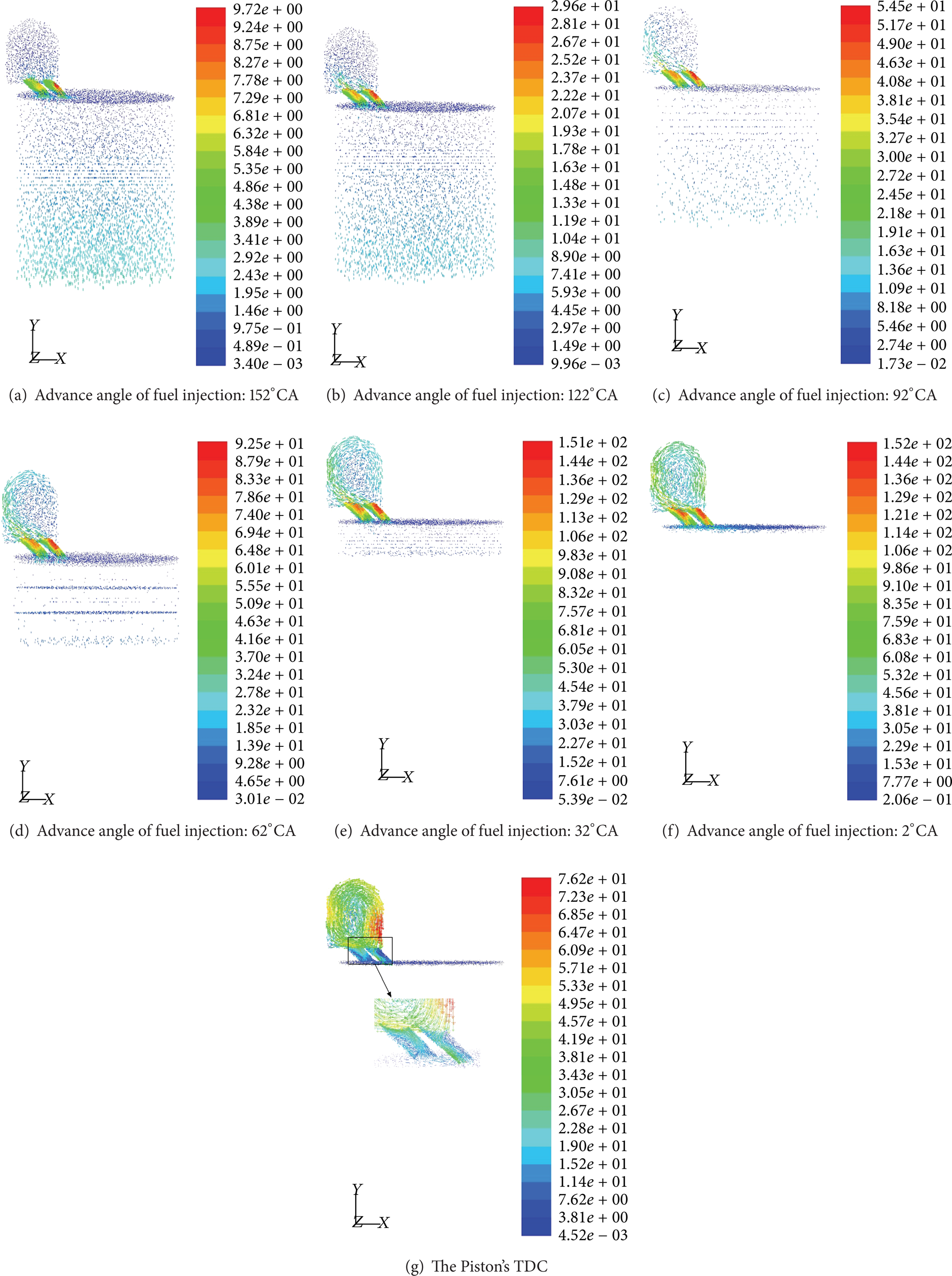
Central section velocity vector diagram of the swirl chamber.
Figure 5 is the variation diagram of pressure field characteristic at the seven advance crankshaft angles of fuel injection. It can be found through observation on the advance angle of 152°CA that the pressure in the cylinder is distributed in a staircase shape, which is mainly caused by the piston's working to compress air in the cylinder. It can be found through observation on the advance angles of 122°CA, 92°CA, and 62°CA that air pressure in the cylinder, though increased, is distributed nearly in the same manner, with only slight staircase phenomenon, and the pressure in the swirl chamber, even increased to some extent, is well distributed. The turbulence and vortex developed gradually in the central zone of swirl chamber minimize the pressure therein. It can be found through observation on the advance angle of 2°CA that with the increase of air compressed into the swirl chamber, as is known from the velocity vector diagram, a larger vortex zone is developed in the centre of swirl chamber and thus minimized the pressure therein; the pressure near the fuel injector nozzle is high but the pressure of the entire chamber is still lower than that in the cylinder and the pressure near the fuel injector nozzle is approximately 4.5 MPa; when the piston has moved to the TDC, with the increase of air compressed into the swirl chamber, a larger vortex zone is developed in the centre of swirl chamber and thus minimized the pressure therein; the pressure near the fuel injector nozzle is high but the pressure of the entire chamber is higher than that in the combustor.

Variation diagram of pressure field characteristic.
Figure 6 is the variation diagram of temperature field characteristic at the seven advance crankshaft angles of fuel injection. It can be found through observation on the advance angle of 152°CA that temperature difference of air in the cylinder is not very great, difference value between the maximum and the minimum is approximately 1°C, and temperature in the vicinity of piston is a little high; this is because air in the cylinder is ideal gas, temperature of which will rise if extruded and the range of temperature rise will increase with the degree of extrusion. It can be found by comparison between the advance angles of 122°CA and 92°CA that the temperature of gas in the cylinder is rising gradually while being disturbed almost in the same manner and the difference between the high and the lower temperature is moderate; however, the temperature difference of gas in the swirl chamber is a little greater; this is mainly because the minor vortex or turbulence developed in the swirl chamber has a certain effect upon the distribution of gas temperature. It can be found by comparison between the advance angles of 62°CA and 32°CA that the temperature of gas in the cylinder is rising gradually and there is difference to some extent between the high and the lower temperature of gas in the swirl chamber as well as in the temperature distribution; this is mainly because the vortex developed in the swirl chamber has a certain effect upon the distribution of gas temperature. It can be found through observation on the advance angle of 2°CA that at this moment the hot space is centred on the left bottom of main combustor and swirl chamber and the temperature near the fuel injector nozzle is approximately 893 K; while when the piston has moved the TDC, the hot space is centred on the swirl chamber, the maximum temperature is 956 K, and the hot air's flow direction is identical with the fuel injection direction; the cause for such high temperature is mainly related to the fluid motion, the fluid first enters into the swirl chamber via the interface channel from the main combustor and then flows out from the starting hole to make the gas temperature in the swirl chamber higher than that in the main combustor, the temperature of air flow close to the wall surface has risen to some extent but a little lower than that in other regions within the chamber, and only the temperature of a small area under the left wall surface of the swirl chamber is high; this is because the energy loss of this air fluid is less and its temperature rise is mainly related to the increase of thermal conduction and internal energy.

Variation diagram of temperature field characteristic.
In the process of piston motion, organized intensive vortex can be developed inside the swirl chamber, the flow velocity close to the left wall surface of swirl chamber is very high, and the temperature in the central region of swirl chamber is very high; however, a small fluid stagnant zone is developed at the left bottom of swirl chamber where the fluid velocity is very low and liable to developing small vortex, which is disadvantageous to the mixing of fuel oil and air.
4. Improved Swirl Chamber Structure
To address the problem that the existence of small vortex at the lower end outside the traditional cylindrical swirl chamber is disadvantageous to the mixing of fuel oil and air, this paper proposes a new type of swirl chamber structure; as shown in Figure 7, the air flow, once accessed to the swirl chamber, will rise along the bevel as well to form a regular vortex, and the bevel is parallel to the interface channel (not approximate to tangency); this has prevented the air flow from causing intense impact to the bevel once accessed to the chamber.

Improved swirl-chamber combustion system.
In comparison with the stroke of piston from the BDC to the TDC in the traditional structure of swirl-chamber combustion system, the phenomenon of fluid stagnant zone developed at the lower end outside the swirl chamber has been obviously improved (we hereby will not go into the detail of flow field circumstance with multiple piston position). With the gradual upstroke of piston, the total volume of cylinder and swirl chamber is minimized, and more and more air is compressed into the swirl chamber, flowing faster and faster; during this period, fastest flow of air is still centred on the right top side of the interface channel and the starting and the vortex is gradually approaching the centre of swirl chamber; however, the small vortex at the lower end outside the chamber has disappeared; in-cylinder temperature is also rising with the increase of air extrusion, and the occurrence of phenomenon that the peripheral temperature of swirl chamber is high while the core temperature is low is earlier than before; this is because the improved regular vortex is developed earlier than before. We hereby take the typical flow field's velocity, pressure, and temperature characteristic diagrams when the advance angle of fuel injection has reached 2°CA for analysis and illustration. It can be seen from Figure 8 that when the advance angle of fuel injection has reached 2°CA, air flows into the swirl chamber via the interface channel to develop an obvious vortex in the chamber, flow velocity in the centre is low while peripheral flow velocity is high, previous small vortex has also disappeared, and the maximum velocity is found at the left top side of the interface channel and the starting hole; with the increase of air compressed into the chamber, a large vortex region has been developed in the centre of swirl chamber to minimize the pressure in such centre and pressure in the vicinity of fuel injector nozzle is very high but pressure in the entire chamber is still lower than that in the cylinder; at this moment the hot space is centred on the main combustor, but an obvious spherical-layered temperature gradient has appeared in the chamber and the temperature is rising from the lowest in the centre outward; this is because an obvious vortex is developed in the chamber, while as the pressure of swirl chamber is lower than that in the main combustor as a whole, only a small portion of gas has flown back to the combustor via the starting hole, and the temperature of the chamber is also lower than that of the combustor.
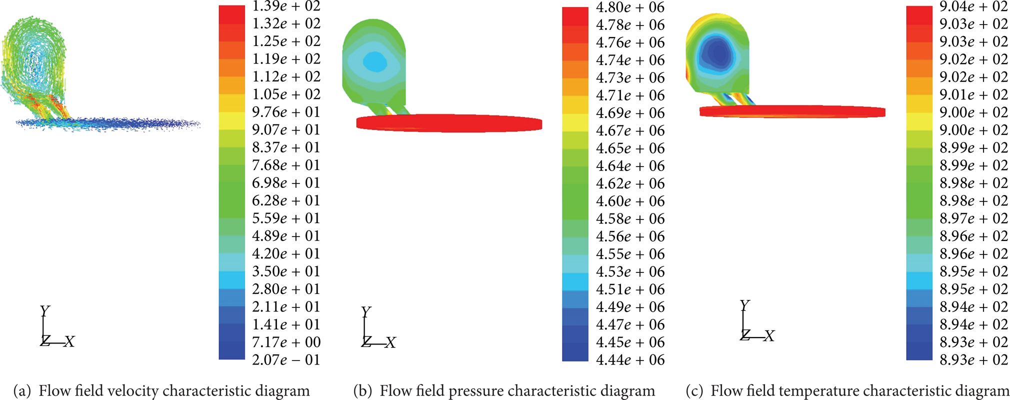
Flow field characteristics of improved swirl-chamber combustion system when the advance angle of fuel injection has reached 2°CA.
At this moment, the flow velocity near the fuel injector nozzle is approximately 83.7 m/s, the pressure is approximately 4.62 MPa, and the temperature is approximately 901 K; under this condition, the demand of diesel oil mixing and combusting in the engine can be better satisfied; during the following temporary period of time from the start of oil injection till the piston's moving to the TDC, the air flow velocity in the chamber has decreased to some extent while both temperature and pressure are rising rapidly; as a result, diesel oil in the engine can be intensively mixed and combusted.
5. Conclusion
This paper performs simulation of the in-cylinder air flow vector diagram, pressure variation diagram, and temperature variation diagram of a certain swirl-chamber turbulent combustion diesel engine within the timeframe from the piston's moving from the BDC to the TDC through FLUENT Dynamic Mesh Technique and analyzed these three diagrams. It can be seen from this simulation that, with the piston's moving from the BDC, air in the cylinder is compressed to the swirl chamber by the piston and to develop a vortex inside the chamber; with the ongoing of compression, both pressure and temperature also rise gradually, till the advance angle of fuel injection has reached 2°CA; the flow field characteristic near the fuel injector nozzle can better satisfy the demand of diesel oil mixing and combusting in the engine.
To address the problem that the existence of small vortex at the lower end outside the traditional cylindrical swirl chamber is disadvantageous to the mixing of fuel oil and air, this paper proposes a new type of swirl chamber structure; it is found through the simulation that, in the process of the piston's moving from the BDC to the TDC, fluid stagnant zone developed at the lower end outside the swirl chamber is disappearing and the small vortex has no longer occurred; when the advance angle of fuel injection has reached 2°CA, the flow velocity near the fuel injector nozzle is approximately 83.7 m/s, the pressure is approximately 4.62 MPa, and the temperature is approximately 901 K; under this condition, the demand of diesel oil mixing and combusting in the engine can be better satisfied.
Conflict of Interests
The authors declare that they have no conflict of interests regarding the publication of this paper.
Footnotes
Acknowledgments
This project was supported by Innovation Platform Open Foundation in Higher Educational Institutions of Hunan Province (09K104) and the Aid Program for Science and Technology Innovative Research team in Higher Educational Institutions of Hunan Province.