
Abstract
The dimpled fin has excellent heat transfer performance and has attracted a lot of attention to apply on the fin and tube heat exchanger. A study presents to investigate the effects of number of tube rows on the air-side heat transfer characteristics of dimpled fin for velocity ranging from 1 to 3 m/s. The Q/ΔP and Q/((ΔP × V)) are used to evaluate the heat transfer performance of the heat exchanger. The results show that the dimpled arrangement can change the mainstream direction, increase the disturbance, and enhance the heat transfer. With the increase of the number of tube rows, the average Nusselt number decreases and Q/ΔP and Q/((ΔP × V)) increase gradually. Compared with the multipipe tube rows, the performance of two-row tube is better.
1. Introduction
Fin and tube heat exchangers are widely used in air conditioning refrigeration industry, chemical industry, food processing industry, and so forth. The main thermal resistances of fin and tube heat exchanger locate at the air side. Therefore, it is important to strengthen the air-side heat transfer. The use of enhanced fin surface is the most effective way to improve the overall performance of the fin and tube heat exchanger. The dimpled surface as a kind of enhanced fin surface can change the main-flow direction, causes better flow mixing, and has been studied extensively in the past.
Afanasyev et al. [1] experimentally researched the turbulent flow and heat transfer characteristic of the dimpled surface. Chen et al. [2] investigated the heat transfer performance of different dimple structure and proposed a correlation which could predict heat transfer coefficient and friction factor accurately. Mahmood and Ligrani [3, 4] compared flow characteristics of dimple channel or without dimple channel. Their results showed that the dimples could produce vortex, secondary flow structure, and flow mixing, and the vortex pairs were periodically shed from the dimples and become stronger as the ratio of channel height to dimple diameter decreased. Won et al. [5] studied the flow structural characteristics over dimpled surfaces located on one wall of a rectangular channel with three different dimple depths. Their results indicated that the deeper dimples ejected stronger primary vortex pairs, which could result in greater mixing, higher local levels of turbulence transport, and turbulence production. Chang et al. [6, 7] experimentally studied the full-field Nusselt number distribution on two opposing enhanced walls with and without dimples. Fan and Yin [8] numerically studied the influence of geometrical parameters on the heat transfer and pressure drop of dimpled jacket in thin-film evaporator. Samad et al. [9] numerically optimized staggered dimple arrays on opposite walls of a channel to enhance heat transfer performance. Results indicated that heat transfer rate increased as the dimple depth increased, and at the same time, pressure drop also increased. Heat transfer characteristics on various dimple/protrusion patterned walls of test channel were researched by Hwang et al. [10, 11]; their results indicated that, for the dimple wall case, the thermal characteristics had similar patterns for the two cases of dimple placed on the single and double walls. However, flow mixing was higher for the double wall than that of the single wall, which resulted in enhanced heat transfer. Isaev et al. [12] numerically studied heat transfer enhancement by a spherical dimple placed on a wall in a narrow channel. The effect of rectangle dimples on the friction of parallel surface at different sliding conditions was introduced by Meng et al. [13]. Their results showed that the dimples could decrease friction of parallel surfaces. Chang et al. [14, 15] experimentally investigated the heat transfer and pressure drop characteristic of hexagonal ducts with three different dimple arrangements. Their results indicated that, at all Re tested, the average Nusselt number followed the order of convex-convex, concave-convex, and concave-concave, and f factors followed the order of convex-convex, concave-concave, and concave-convex. Vortex structures and heat transfer enhancement mechanism of turbulent flow over a staggered arrangement of dimples were investigated by Turnow et al. [16, 17]. It was found that there was a maximum thermohydraulic performance when the depth to diameter ratio was 0.26. Seo et al. [18] studied the heat transfer performance of the dimpled tube and pointed that the heat-exchange efficiency of the dimpled tubes was higher than the flat tubes. In order to study the coherent vortex structure and get a deep insight into flow physics, the flow characteristics of the dimples were researched by Voskoboinick et al. [19]. Sethi et al. [20] experimentally investigated the effect of artificial roughness on heat transfer performance of the solar air heater dimpled duct, and they derived Nusselt number and friction factor correlations by the experimental data. Choi et al. [21] studied the heat transfer performance of the channels with both angled ribs and dimples and indicated that the angle ribs could produce secondary flow and the dimples could enhance the heat transfer performance but the pressure loss increased reasonably. J. Lee and K.-S. Lee [22] numerically studied the heat transfer performance of plate heat exchangers with dimples and protrusions, and based on the results, they gave the Nusselt number and friction factor correlations. Katkhaw et al. [23] studied 10 types of dimple arrangements and dimple intervals on flat surfaces. The results showed that the heat transfer coefficients for dimpled surfaces of staggered arrangement were about 15.8% larger than that of smooth surface. Bi et al. [24] numerically investigated the performance of dimpled, cylindrical grooves and low fins minichannels. The results show that the dimple surface had the highest performance. Xie et al. [25, 26] numerically investigated flow characteristics and heat transfer performance for a rectangular channel surface with internal-protruded dimples. Tay et al. [27] applied the flow visualization method to study the various flow structures as ReD varied from 1000 to 28000.
The foregoing literature reviews show that the dimple can generate the secondary flow, vortex structures, which can efficiently enhance heat transfer performance. So the dimples have been applied in fin and tube heat exchangers in order to improve the air-side heat transfer. Fan et al. [28] numerically studied the characteristics of the shallow ellipsoidal dimpled fins and analyzed the heat transfer and flow characteristic of the staggered arranged three-row shallow ellipsoidal dimpled fins. Elyyan and Tafti [29] introduced the split-dimple fin to enhance heat transfer rate by perturbing continuous boundary layer formation on the fin surface and generating energetic shear layers, but at the same time the friction also becomes larger. Song et al. [30] regularly arranged some dimples on the single tube fins of air coolers and simulated the flow and heat transfer performance of air-side dimpled fins and pointed out that, at the same of the dimple number, staggered arrangement was superior to the sequential (in-line), and suitable dimple size and arrangement in direct air cooling single serpentine fin tube could achieve better heat transfer than flat fins. Kim et al. [31] optimized the heat transfer of staggerd elliptic dimple fin and aimed to enhance heat transfer and reduce the resistance loss. Rao et al. [32–34] investigated heat transfer performance in rectangular channels with pin fins and dimple-pin fins, and they suggested that, compared with the pin fins, the dimple-pin channel had distinctive local heat transfer characteristic on the main flow and wake flow region. The dimples could improve turbulent mixing and enhance heat transfer rate. They experimentally studied channel pressure drop and heat transfer characteristic in different dimple heights and revealed the underlying mechanisms for the associated dimple depth dependent pressure loss and heat transfer characteristics in the pin fin-dimple channels. Wu et al. [35] indicated that the dimpled fin had excellent heat transfer performance. They used orthogonal experimental design method to optimize the structure of dimpled fin. Shokuhmand et al. [36] studied that the effects of dimples on the flow structure and heat transfer performance of the louver fins. Their results showed that dimple structure could raise the heat transfer capacity by 5% in fin banks.
As shown from the previous literature, the dimpled structure can enhance the heat transfer, but the study about the dimple surfaces is less involved in the aspect of the effect of multirow tubes on the flow and heat transfer characteristic of the dimpled fin, so the purpose of this paper is to study the performance of dimpled fins with multirow tubes.
2. Physical Model and Computational Methods
2.1. The Physical Model
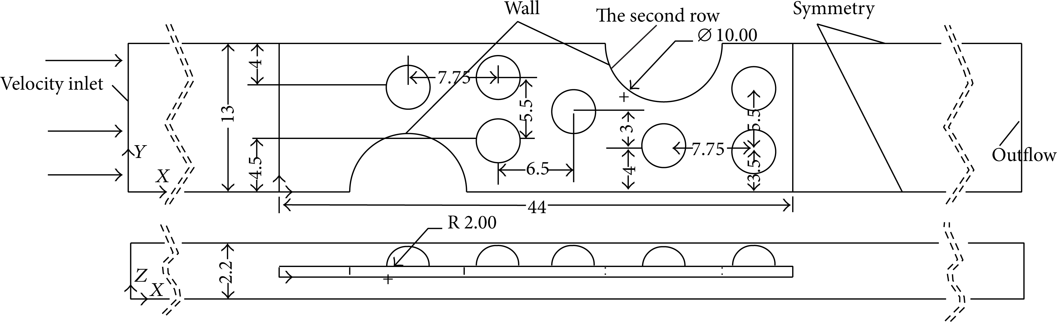
A schematic of the dimpled fin and tube heat exchanger is depicted in Figure 1; the dimples are arranged based on the “front coarse and rear dense method”. The computational model in this paper is shown in Figure 2, which takes into account the area between adjacent fins as the calculation region, and the inlet extends 1.5 times of the fin length in order to obtain a uniform velocity distribution, and the outlet extends 9 times of the fin length at the outlet in order to ensure no recirculation at the outlet boundary.

Heat exchanger (N = 2).
The simulation model (N = 2).
The geometric sizes of the fin are listed in Table 1.
The geometric size of the fin.

2.2. Numerical Models
The governing equations for three-dimensional, turbulent flow, incompressible with constant properties and steady and no viscous dissipation, can be expressed as follows. The general control equation is as follows:

where φ is the universal variables, Γφ is generalized diffusion coefficient, and Sφ is generalized source term corresponding to the φ values. The terms of governing equation are as shown in Table 2.
Control equations.
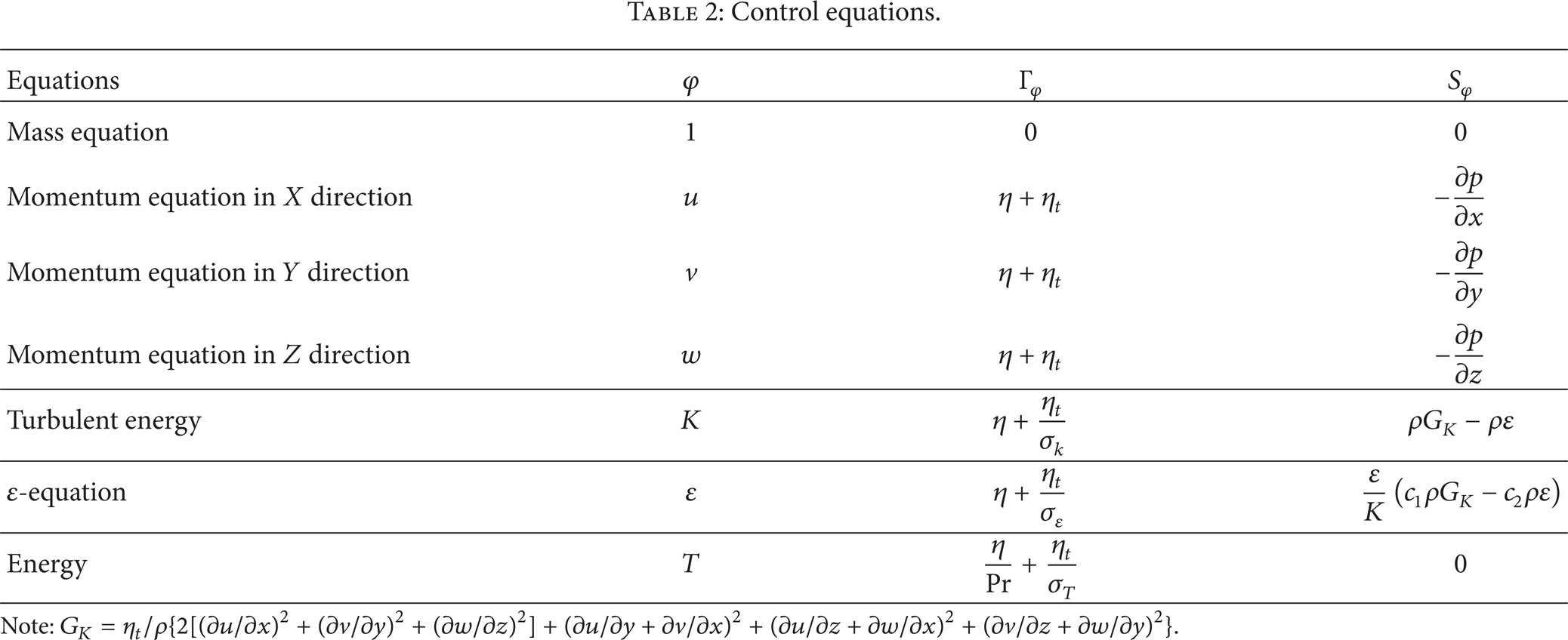
Note:
The boundary conditions are described as follows.
No slip conditions are at the solid surfaces.
Conjugate heat transfer is amid fin and airflow.
The air inlet temperature is fixed as 308 K, and the tube wall temperature is set at 318 K.
The material of the heat transfer tube is copper, and fin's material is aluminum. As is given in Figure 2, the outlet is set as the full development boundary conditions; at the up and down faces, the periodic boundary conditions are given; the right and left boundaries are symmetric boundary conditions.
The SIMPLE algorithm is applied to deal with the coupling of pressure and velocity, second-order upwind scheme is used to discretize the governing equations. A k-ε turbulence model is employed to investigate the turbulent flow field. The convergence criteria are that the residuals of the continuity equation and momentum equation are below 10−6, while the residual of energy equation is below 10−8.
In order to validate the accuracy of computational results, the grid independence of the numerical solutions has been made. For this purpose, the grid independence test is carried out for all the computing models; for example, the number of tube rows is 2, and three different grids number are studied. The grids numbers are 931928, 1361481, and 1840656. The heat transfer coefficients of three sets of grid number are listed in Table 3. The relative errors of three sets of grid number are much less than 0.7%. Therefore, in order to obtain the accurate results and save computer resource, the grid of about 1361481 is used for further computation.
The independence test.

2.3. Parameter Definition
The definition of each parameter is shown as follows [37]:
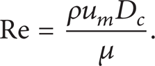
Reynolds number is
Nusselt number is

The surface heat transfer coefficient is

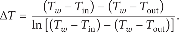
Logarithmic mean temperature difference is
The fin efficiency is

where
Colbum factor is

Friction factor is

3. Results and Discussions
3.1. The Fluid Flow and Heat Transfer Performance
When the number of tube rows is 2, The Nusselt number and the friction factor of dimpled fin and plain fin are plotted in Figures 3 and 4, respectively. Compared with the plain fin, it can be seen that the average Nusselt number and friction factor of dimpled fin increases by 44%∼64% and 34%∼36%, respectively. So the dimpled fin can enhance the heat transfer.
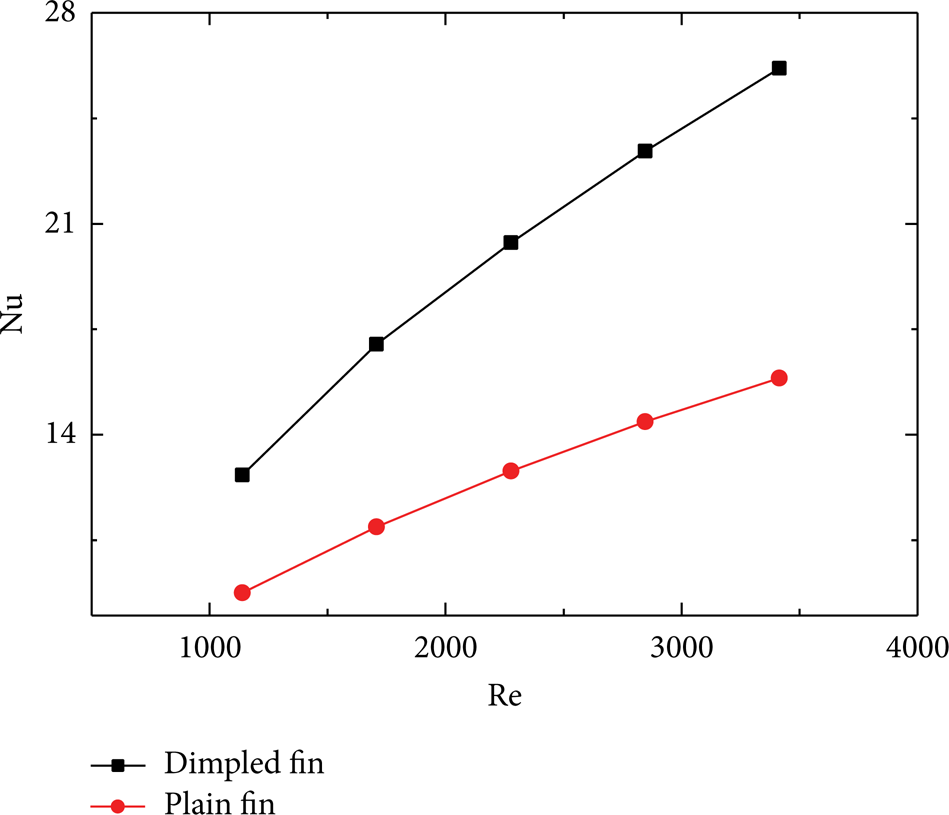
Nusselt number.

The friction factor.
The Q/ΔP and Q/((ΔP × V)) is used to evaluate the heat transfer performance of heat exchanger, where Q is the heat exchange rate, ΔP is pressure drop in flow direction, V is the volumetric flow rate, and Q/((ΔP × V)) is represented as COP, which is characterized by the change of the ratio between actual heat transfer rate and the pumping work. The effect of tube numbers on the Q/ΔP is depicted in Figure 5. Q/ΔP decreases with increasing of number of tube rows, but with the increase of Reynolds number, Q/ΔP decreases slowly. The comparison of COP for different number of tube rows is displayed in Figure 6, and it is clear that the values of COP decrease with the increasing Reynolds number. The bigger the Q/ΔP and COP are, the better the heat transfer performance is. So the heat transfer performance of N = 2 is better than that of N = 3, 4, 5.

Q/ΔP under different number of tube rows.

COP under different number of tube rows.
The trend of Nu number versus Re number is given in Figure 7. It can be seen that the average Nu number for N = 2 is bigger than that for N = 3, 4, 5. Compared with the N = 3, 4, 5, at Re = 3415, average Nusselt number of N = 2 increases by 8.39%, 20.4%, and 20.53%, respectively. At the same time, Q/ΔP and COP decrease with the number of tube rows increasing. At the same number of tube rows, they decrease as the velocity increases. So the comprehensive performance of N = 2 is best, and three, four, and five rows tube dwindle.

Nu number under different number of tube rows.
3.2. The Comprehensive Performance Analysis
The ratio j/f1/3, that is, JF factor, is an index in evaluating comprehensive performance of the fin surface. The larger the JF factor is, the better the comprehensive performance is. As can be seen from Figure 8, the JF factor of N = 2 is the biggest, which is 17%, 27%, and 29% bigger than the value of N = 3, 4, 5, respectively. So the comprehensive performance of the two-tube row is better.

Comparison of the overall performance.
3.3. The Field Synergy Principle Analysis
The synergy angle is defined as an indication of the synergy degree between velocity and temperature field for the entire flow and heat transfer domain. It is defined as:

As is depicted in Figure 9, The average field synergy angle for N = 2 is smaller than N = 3, 4, 5. So the synergy of the velocity and temperature gradient is better when the number of tube rows is 2.
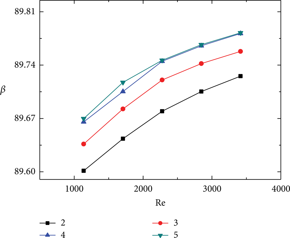
Average field synergy angle.
3.4. Flow Field Analysis
The flow field of different number of tube rows is described in Figure 10; it can be seen that there is a wake region behind the tube, which is not a benefit to heat transfer, so the arrangement of the dimple should change the flow direction and induce the fluid into this zone, which can enhance the heat transfer.

The flow field at the v (velocity) = 2 m/s.
As is shown in Figure 11, when the flow is across the concaves, it can form vortices, which can enhance heat transfer. With the increase of the number of tube rows, for the Figures 11(c) and 11(d), the temperature of the around dimple increases, so the heat transfer performance of N = 2, 3 is better than that of N = 4, 5.

The flow field at the cross-section of yz coordinates, v = 2 m/s of different number of tube rows.
4. Conclusions
The paper presents the effects of tube rows on the flow structure and heat transfer performance. The investigated results show that the fluid across the dimple concave can form a flow structure like a ponytail streamlines, which can enhance the heat transfer performance. The average Nusselt number, Q/ΔP, and COP decrease with the increase of the number of tube rows. At the same number of tube rows, they decrease as the velocity increases. The values of Q/ΔP and COP are the largest at two-row tube. Compared with the three-, four-, five-row tube, the average Nusselt number of two-row tube increases by 8.39%, 20.4%, and 20.53% at Re = 3415, respectively. The JF factor of the two-row tube is 17%, 27%, and 29% bigger than the value of 3-, 4-, 5-row tube, respectively. So the comprehensive performance of the two-row tube is better.
Conflict of Interests
The authors declare that there is no conflict of interests regarding the publication of this paper.
Footnotes
Acknowledgments
The present work is supported by the Project of National Natural Science Foundation of China (no. 51476148), Henan Province, and College Cooperation Projects (no. 092106000013), the Foundation for University Key Teacher (2012GGJS-115), and Innovation Scientists and Technicians Troop Construction Projects of Zhengzhou City (131PLJRC640).