
Abstract
This paper reports experimental and computational fluid dynamics (CFD) modelling studies to investigate the effect of the swirl intensity on the heat transfer characteristics of conventional and swirl impingement air jets at a constant nozzle-to-plate distance (L = 2D). The experiments were performed using classical twisted tape inserts in a nozzle jet with three twist ratios (y = 2.93, 3.91, and 4.89) and Reynolds numbers that varied from 4000 to 16000. The results indicate that the radial uniformity of Nusselt number (Nu) of swirl impingement air jets (SIJ) depended on the values of the swirl intensity and the air Reynolds number. The results also revealed that the SIJ that was fitted with an insert of y = 4.89, which corresponds to the swirl number Sw = 0.671, provided much more uniform local heat transfer distribution on the surface. The CFD-predicted results help to explain the experimental measurements in terms of the turbulence intensity. Furthermore, the predicted and measured local Nusselt numbers were consistent with each other.
1. Introduction
Heat exchangers with convective heat transfer are widely used in many engineering applications. The augmentation of heat transfer in all types of thermotechnical apparatus significantly saves the primary energy and reduces the size and weight of the heat exchangers. In general, heat transfer augmentation techniques are classified as passive and active. The passive methods require special surface geometries or swirl/vortex flow devices, whereas the active techniques require external forces, such as an electric field, surface vibration, or jet impingement. Jet impingement is one of the active techniques that is widely used in several engineering applications because of its promising characteristics, such as high heat transfer rate and low cost. The applications include heating steel plates, cooling turbine blades and electronic components, tempering glass, and drying papers and food products. A number of experimental and numerical investigations have been attempted regarding the effects of single and multiple jets and impinged surface geometries on the mass and the heat transfer [1–10]. Introducing a swirl motion into an impinging jet is considered an effective means to expand the heat transfer area compared to the conventional jet. Bakirci and Bilen [11] investigated the temperature distribution and the heat transfer rate on impingement. The surface was maintained at a constant wall temperature boundary condition for the swirling (SIJ), multichannel (MCIJ), and conventional impinging jets (CIJ) using the liquid-crystal technique. Swirl generators with swirl angles of 0°, 22.5°, 41°, and 50° were used to change the direction and strength of the swirl in the air flow that exited the jet nozzle. According to the results, the radial uniformity of the local and average Nusselt numbers improved when the swirl angle and/or jet spacing was increased. Ianiro and Cardone [12] performed an experimental analysis of the heat transfer distribution on a flat plate under arrays of swirling impinging jets using infrared thermography and with heated thin-foil sensor for the measurement. Helical inserts were used to generate five swirl number (Sw) values (0, 0.2, 0.4, 0.6, and 0.8) for five nozzle-to-plate distances (z) (2, 4, 6, 8, and 10 D). The results indicated that the multichannel jet enhanced heat transfer unlike the common circular impinging jet. However, it was reported that the swirl motion decreased the heat transfer rate but improved the radial uniformity of the heat transfer. Nanan et al. [13] empirically investigated the convective heat transfer that was associated with swirling impinging jets on an impinged plate using twisted tape inserts. The effect of the twist ratio (y/W), jet-to-plate spacing (L/D), and jet Reynolds number (Re) on the local/average Nusselt number on the impingement plate was reported. The results showed that the maximum local/average Nusselt number on the impingement plate was achieved at the largest twist ratio, the smallest jet-to-plate spacing, and the highest jet Reynolds number. Nuntadusit et al. [14] studied the effect of the swirl number on the flow and heat transfer characteristics in an impinging jet on an impinged surface using straight and twisted tape inserts. They visualized the flow pattern and the temperature distribution and evaluated the heat transfer rate of the swirling impinging jet using oil film and thermochromic liquid-crystal techniques. Nuntadusit et al. [15] also reported the flow and the heat transfer in multiple swirling impinging jets with 3 × 3 in-line arrangement on a flat, heated surface using the same techniques for the flow and heat measurements. The outcome signified that the multiple swirling impinging jets offered a higher heat transfer rate on impinged surfaces than the multiple conventional impinging jets for all jet-to-jet distances. In the present work, the effect of swirl jets on a heated impinged surface plate using classic twist tape inserts with twist ratios y = 2.93, 3.91, and 4.89 is reported. The performance of the insert is evaluated in terms of the measured increase in local Nusselt number values and the uniformity of their radial distributions on the impinged surface. The operational performance of these inserts is experimentally and theoretically compared with that obtained for conventional jets.
2. Experimental Work and Uncertainty Analysis
The experimental setup schematic is illustrated in Figure 1. An air jet is supplied to the system through a pressure regulator, using a compressor, condenser, air filter, and flow meter. The air filter was installed between the air tank and the flow meter to clean the air from oil and other impurities. The air was directed toward the impingement surface passing through a rubber hose and a circular, 1 m long aluminum pipe with 21 mm inner diameter and 3.5 mm wall thickness. Because the ratio of the pipe length to the nozzle diameter was 47, a fully developed flow was used at the pipe nozzle entrance. The applied pipe nozzle was 21 mm in inner diameter and 300 mm long. Classical twist tapes with different twist ratios (y = 2.93, 3.91, 4.89) served as inserts to generate the swirl motion; these inserts are made from aluminum strips with width of w = 20 mm and thickness of δ = 0.8 mm.

Schematic diagram of the experimental setup. (1) Air compressor; (2) air tank; (3) open-close valve; (4) pressure regulator; (5) heat exchanger; (6) air filter; (7) flow meter; (8) jet pipe; (9) thermocouple; (10) heat flux sensor; (11) thermocouple; (12) AC power supply; (13) data logger; (14) impingement plate.
The twist ratio was obtained by uniformly winding the strip for over 300 mm. The twist ratio “y” is defined as the ratio of the length of one full twist (360°) to the width of the twist [16]. Figure 2 shows an illustration and the details of the twisted tapes that were used in this study.

(a) Twisted tapes at various twist ratios and (b) pipe nozzle with twisted tape.
The swirl intensity for a classical twisted tape is varied by changing the number of pitches per twisted tape length. The swirl intensity is represented by the swirl number, which is defined as follows:

where Gθ is the axial flux of the azimuthal momentum, G n is the axial flux of the axial momentum, and R is the radius of the pipe nozzle.
In this study, the effect of the boundary layer in the pipe nozzle is ignored; the axial velocity and the angular velocity are assumed to be constant along the cross section of the nozzle exit. Thus, Gθ and G n can be expressed as

where V n , Vθ, and w are the azimuthal velocity, the axial velocity, and the angular velocity, respectively.
The angular velocity can be calculated from the twisted pitch number (n) and the length of the twisted tape (l = 300 mm) as follows:

From (1)–(3), a modified swirl number is obtained and defined as

The modified swirl numbers (Sw) with different twist ratios are provided in Table 1.
Twist ratio with modified swirl number.

The impinged plate was 300 mm wide and 300 mm long. The electric heater sheet was made from stainless steel with a width and a length of 300 mm and 300 mm, respectively. The heater sheet was imbedded between the impinged plate and a thick 300 × 300 mm mica plate to minimize and disregard the lateral heat conduction. The back side of the impinged plate was embedded with brass plated with a chrome-type K thermocouple using a thermally well-conductive paste as an adhesive layer to diminish the disturbance on the thermocouple's signal. AC electric current was conducted to the electric heater sheet via uniform heat generation using a power supply unit with a TC4S temperature control system. The temperature and the heat flux of the impinged plate were examined overall using HFX-4 Thin-Film Heat Flux Sensors in a GL220 Data Logger. The surface temperature at different locations on the impingement plate was measured and compared with the temperature on the back side, which showed that the difference was less than 0.5°C under the tested conditions.
The experimental data on the heat transfer rate are expressed in terms of the local Nusselt number and the local convective heat transfer coefficient at the impingement plate as follows:

where D is the nozzle diameter, h is the heat transfer coefficient, and k is the conductivity of air based on the reference temperature of 25°C:

where q* is the heat flux that was measured using the HFX-4 Thin-Film Heat Flux Sensors, T w is the impingement wall temperature that was measured using the HFX-4 Thin-Film Heat Flux Sensors, and T j is the air temperature at the nozzle exit, which was measured using a K-type thermocouple.
In addition, the Reynolds number is obtained according to the following equation:

where u is the average velocity at the exit of the nozzle, D is the nozzle diameter, ρ is the air density based on the reference pressure and temperature of 1 atm and 25°C, respectively, and μ is the air viscosity based on the reference pressure of 1 atm and the reference temperature of 25°C.
A standard uncertainty analysis was conducted for each measurement to determine the maximum expected deviation from the experimental results of the local Nusselt number using the uncertainty equation for product functions, which was provided in Holman [17]:

where w R is the uncertainty of result R and w x i is the uncertainty of the independent variables xi upon which R = R(x i ). For the Nusselt number, the xi included the heat flux q, the air jet temperature (T j ), the surface temperature of the impingement plate (T s ), and the jet nozzle diameter (D). The final uncertainty equation of the local Nusselt number was derived from (8) as follows:

Using the respective data that are provided from the manufacturers, the accuracy of the HFX-4 Thin-Film Heat Flux Sensor was 0.02% and 0.0005 (T s + 1) for the heat flux and the surface temperature, respectively. The temperature accuracy for the K-type thermocouple was 0.77%, and the nozzle diameter, which was measured using a Vernier calliper, was 0.25%. Consequently, the maximum uncertainty that is associated with the local Nusselt number was calculated to be 2.92% and 2.78% for Reynolds numbers of 4000 and 16000, respectively.
3. Experimental Results
3.1. Validation of Results
Before performing the experiments with a swirl jet, the heat transfer results that were obtained using the conventional impinging jet (CIJ) were compared with the experimental works of Nanan et al. [13], Gulati et al. [18], and Choo and Kim [19], as shown in Figure 3.

Comparison between the present work and the previous studies.
3.2. Effects of the Twisted Tape Ratio and Jet Reynolds Number
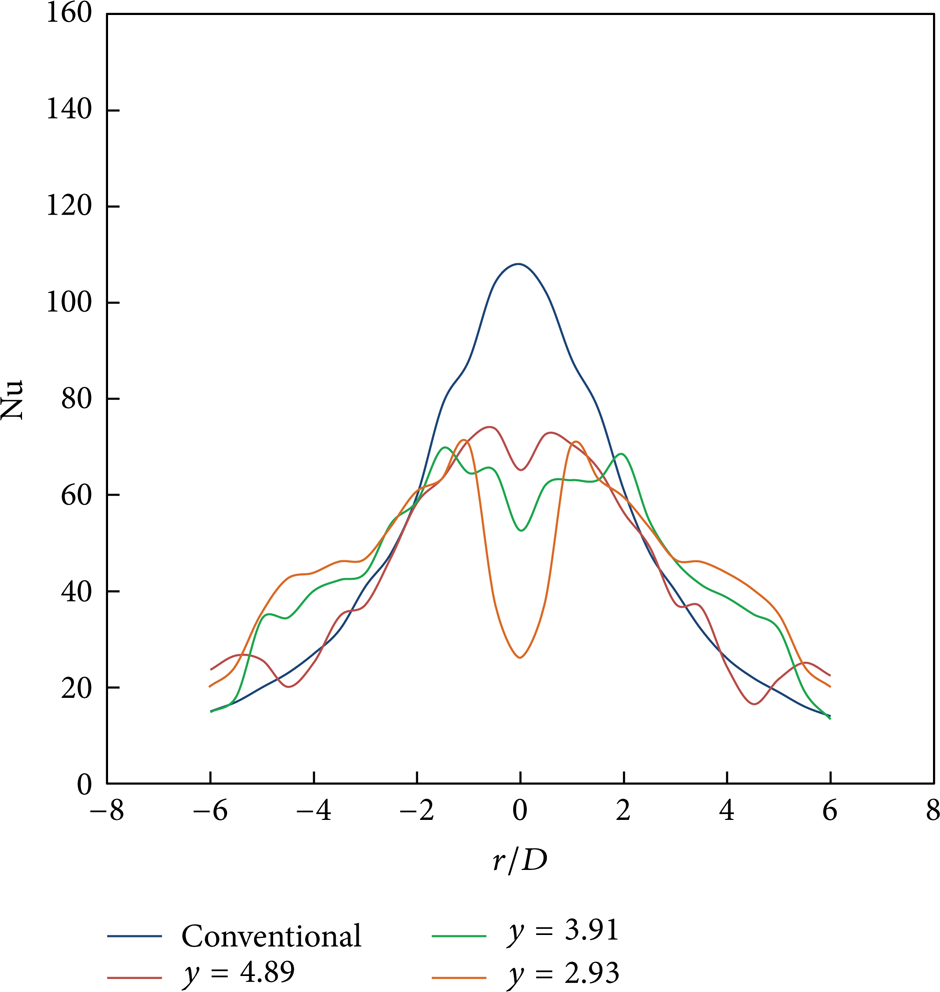
The effect of the twist ratio of the twisted tape on the local Nusselt number distribution of a swirling impingement jet is illustrated in Figures 4, 5, 6, and 7. The Nusselt distribution of the conventional impinging jet (CIJ) showed one peak at the stagnation point (r/D = 0) and an abrupt change along the radial axis. However, the swirling impingement jets (SIJ) exhibited two peaks, which were related to the impingement of the two jets that were produced from both sides of each twisted tape. Similar findings in multiple jets were reported in [13, 14]. From Figures 4–7, it is obvious that the largest twist ratio (y = 4.89) produced a higher Nusselt number than the other ratios. This result indicates that the axial momentum distribution that was induced by a large twist ratio was less significant than the one with a small twist.

Effect of the twist ratio (y/W) on the local Nusselt number distribution for Re = 4000.
Effect of the twist ratio (y/W) on the local Nusselt number distribution for Re = 8000.

Effect of the twist ratio (y/W) on the local Nusselt number distribution for Re = 12000.

Effect of the twist ratio (y/W) on the local Nusselt number distributions for Re = 16000.
4. Numerical Simulation
The FLUENT-6.3.26 commercial CFD package was used to perform 3D calculations of the convective heat transfer on the impinged plate, which is associated with conventional and swirling impinging jets. The model helped us predict and explain the experimental observations. The computational domain consisted of the entire pipe-plate assembly as shown in Figure 8: a cylindrical tube that was 21 mm in diameter and 300 mm long with a helical twist configuration, whose twist ratios were 2.93, 3.91, and 4.89. The geometry of the twisted tape inserts with different twist ratios was made by winding a 20 mm wide uniform strip using the twist option in face sweeping.

Swirling impinging jet assembly.
Twist angles of 360° with lengths of 58.6, 78.2, and 97.8 mm for twist ratios of 2.93, 3.91, and 4.89 were generated using a perpendicular type of sweeping for the entire 300 mm. The details of the geometry, physical properties, and boundary conditions are provided in Table 2. The boundary conditions represent the experimental conditions with respect to the temperature and velocity of the impinging jet, the temperature of the ambient air, and the temperature of the plate.
Geometry, flow, and physical properties.

To adequately calculate the heat transfer, the turbulent flow fields in a particular layer through which heat is transferred must be accurately predicted. A segregated solver algorithm was selected as a solver with the settings of implicit formulation, time-independent calculation, viscous turbulent models, and energy equation. SIMPLE, which was the pressure-velocity coupling method and the second-order upwind scheme for the energy and momentum equations, were used to solve the model. The turbulent models are based on the Reynolds averaged Navier-Stokes equations for 2D and 3D domains. Furthermore, a default value for the convergence criterion was chosen for all calculated parameters.
The following equations calculate the convective heat transfer in terms of the local Nusselt number and the local heat transfer coefficient:

where h is the heat transfer coefficient, D is the nozzle diameter, and k is the air conductivity:

where q* is the convective heat flux, T w is the impingement wall temperature, and Tref is the reference temperature, which is defined in the reference values panel that is available in FLUENT.
There are two definitions of Tref: the local adiabatic wall temperature, which is used by Gardon and Cobonque [20] and Goldstein et al. [21] or the jet exit temperature. In the present study, the jet exit temperature was close to the ambient temperature, T a -T j = ± 0.1°C; therefore, it was applied to calculate the local Nusselt number instead of the local adiabatic wall temperature.
5. Validating the Model
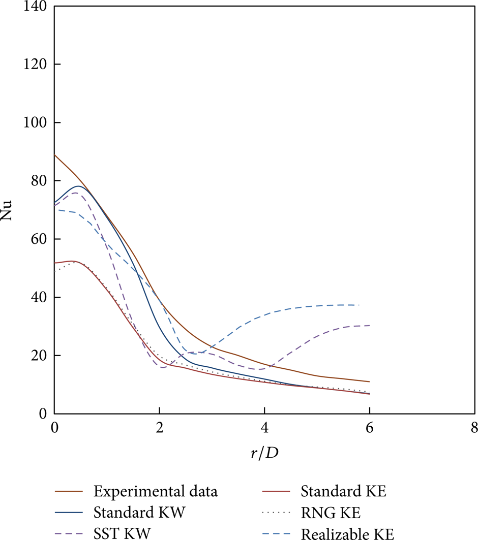
Experimental data for a conventional impinging jet were used to validate the CFD calculation models, which are shown in Figures 9 and 10. Five turbulence models were available in the ANSYS release 12.1: standard k-ε, RNG k-ε, realizable k-ε, standard k-ω, and shear stress transport (SST) k-ω, and they were tested to select an optimum model for simulation. The enhanced wall treatment was used for standard k-ε, RNG k-ε, and realizable k-ε. The enhanced wall treatment requires a fine mesh near the wall; therefore, 10 cells in the inner layer were chosen for the impingement plate surface to make y+ ≈ 1. Meanwhile, the standard k-ω model and the shear stress transport (SST) k-ω model do not have the options of enhanced wall treatment. The simulation results revealed that the Nusselt number behaved differently from the experimental data near the stagnation region regardless of the turbulence model that was used, and this trend was closely reproduced by the turbulence model. The ideal model to predict the Nusselt number distribution along the radial direction is ST k-ω. The numerical Nusselt number values that were obtained from this model are consistent with the experiments; the error was within 1–10% for 0.5<r/D<2.
Nusselt number distribution for the single jet impinging on a flat plate at H/D = 2 and Re = 4000.

Nusselt number distribution for the single jet impinging on a flat plate at H/D = 2 and Re = 12000.
6. Swirling Impinging Jet (SIJ) Simulation
6.1. Local Nusselt Number
Figures 11, 12, 13, and 14 show the numerical Nusselt number distribution values along the radial direction using the ST k-ω model of the conventional impinging jet (CIJ) and the ST k-ε model for a swirl jet. It is noted that the Nusselt number of the conventional jets differs from the experimental data near the stagnation region (0<r/D<0.5) as previously mentioned, and the maximum Nusselt number value occurs at the stagnation point r/D = ± 0.5. Moreover, the locations of these points do not appear to change with an increasing Reynolds number. For the swirling impinging jets (SIJ), it is evident that the heat transfer behavior has similar patterns because double peaks of the Nusselt number are identified in the impingement region. The locations of these peaks appear to shift further in the vertical direction when the twist tape ratio increases, which coincides with the experimental results.

Effect of the twist ratio (y) on the local Nusselt number distribution for Re = 4000.

Effect of the twist ratio (y) on the local Nusselt number distribution for Re = 8000.

Effect of the twist ratio (y) on the local Nusselt number distribution for Re = 12000.

Effect of the twist ratio (y) on the local Nusselt number distribution for Re = 16000.
6.2. Nusselt Number
The Nusselt number contours for conventional jet and swirl jet via CFD simulation with Re = 12000 are shown in Figures 15, 16, 17, and 18. The figures indicate that the maximum heat transfer rate is found at the stagnation point for a conventional impinging jet, whereas the maximum heat transfer location shifts away from the stagnation point for the swirling jets because of the high tangential velocity components. For all swirling jets, the heat transfer regions are separated because of the blockage by the twisted top ridge, and the separation becomes notable as the twist ratio decreases. The maximum heat transfer rates of the nozzles with twist tapes of y = 4.89 appear to be higher than those obtained with twist tapes of y = 3.91 and y = 2.93. This result could be caused by the subsidizing effect of the axial velocity intention by increasing the spreading rate prior to impingement.

Map of Nusselt number contours for the conventional jet.

Map of Nusselt number contours for the swirl jet with y = 2.93.

Map of Nusselt number contours for the swirl jet with y = 3.91.

Map of Nusselt number contours for the swirl jet with y = 4.89.
7. Conclusions
The present study experimentally and numerically investigated the effects of the twist ratio (y), which corresponds to the swirl intensity, and the jet Reynolds number on the local Nusselt number distribution on an impingement plate that was heated to 50°C. Classical twist tapes with three twist ratios (y = 2.93, 3.91, and 4.89) were used as the jet nozzle inserts at a jet-to-plate spacing of L/D = 2 and four different jet Reynolds numbers (4000, 8000, 12000, and 16000). The results were compared with those for a conventional jet, and, evidently, the conventional jet has a greater maximum local Nusselt number than the swirl jets. Furthermore, the swirl jet with the largest test ratio (y = 4.89) enhanced the heat transfer rate more than the swirl jets with y = 2.93 and 3.91. Numerical simulations of the impinging jet flow were performed to validate and explain the experimental observations of various turbulence models. The computations show that the predicted results of the ST k-ω turbulence model are reasonably consistent with the experimental results for conventional jet, whereas the ST-k-ε model was more consistent with the swirl jets than the other models. Contour plots of the predicted Nusselt number were additionally presented. The obtained results demonstrate that the conventional-jet heat transfer rates were greater than the heat transfer rate of the nozzle with twisted tape inserts (y = 4.89, 3.91, and 2.93). These results are consistent with the experimental work.
Footnotes
Nomenclature
Conflict of Interests
The authors declare that there is no conflict of interests regarding the publication of this paper.
Acknowledgments
The authors would like to thank the National University of Malaysia and the Ministry of Higher Education for the financial support (FRGS/1/2013/TK07/UKM/01/1 and DPP-2013-114) to perform this investigation.