
Abstract
Vibration-based damage detection, a nondestructive method, is based on the fact that vibration characteristics such as natural frequencies and mode shapes of structures are changed when the damage happens. This paper presents cooperative coevolutionary genetic algorithm (CCGA), which is capable for an optimization problem with a large number of decision variables, as the optimizer for the vibration-based damage detection in beams. In the CCGA, a minimized objective function is a numerical indicator of differences between vibration characteristics of the actual damage and those of the anticipated damage. The damage detection in a uniform cross-section cantilever beam, a uniform strength cantilever beam, and a uniform cross-section simply supported beam is used as the test problems. Random noise in the vibration characteristics is also considered in the damage detection. In the simulation analysis, the CCGA provides the superior solutions to those that use standard genetic algorithms presented in previous works, although it uses less numbers of the generated solutions in solution search. The simulation results reveal that the CCGA can efficiently identify the occurred damage in beams for all test problems including the damage detection in a beam with a large number of divided elements such as 300 elements.
1. Introduction
Nondestructive methods are important for structural integrity testing. The vibration-based damage detection methods are nondestructive methods for structural damage identifications. Once the damage is originated in a structure, vibration characteristics such as natural frequencies and mode shapes of the structure are changed. Theoretically, the vibration characteristics depend on the structural physical parameters such as mass, stiffness, and damping. The structural damage causes a reduction of structural stiffness so that vibration characteristics are consequently changed. Vibration-based damage detection predicts the location and amount of the occurred damage in the structure by evaluating the changes in the vibration characteristics.
The vibration-based methods for damage detection have been developed for the applications of civil engineer and mechanical engineer [1–3]. The residual force concept has received wide attention with regard to the damage detection and assessment [4–6]. This concept provides a minimized objective function numerically calculated from the differences between the vibration characteristics of the actual damage and those of the predicted damage.
In optimization process, there are two main optimization approaches: derivative-based and derivative-free methods. Compared to the derivative-based schemes, the derivative-free methods do not need a functional derivative of a given objective. They, instead, rely on the repeated evaluations of the objective functions and perform the search direction under the nature-inspired heuristic guidelines. Although the derivative-free schemes are generally slower than the derivative-based methods, they are much more effective for the complicated objective functions and combinatorial problems as the methods do not require differentiable objective functions.
Genetic algorithm (GA) [7, 10] is a derivative-free population-based optimization method of which search mechanisms are based on the Darwinian concept of survival of the fittest. A number of works employed GAs to solve the structural damage detection problems such as [5, 6, 11–16]. Rao et al. [5] used a two-point crossover binary coded GA with tournament selection for reproduction of population. A direct concept of the residual force matrix is used to specify an objective function. He and Hwang [13] proposed a hybrid algorithm, simulated annealing genetic algorithm, which combined an adaptive real-parameter genetic algorithm with a simulated annealing for damage detection. The objective function is a combination of the difference between measured and theoretically computed displacements and the difference between measured and theoretically computed natural frequencies. Panigrahi et al. [6] employed GA with the concept of the residual force matrix for the damage detection in uniform strength beams.
Some previous researches implemented other evolutionary computing techniques such as ant colony optimization [17] and particle swarm optimization [18, 19] for the structural damage detection. Moreover, there are a number of works [20–22] that formulated the structural damage detection as multiobjective optimization problems having a number of objectives evaluated from the differences between measured and theoretically computed vibration characteristics.
The previous works were focused upon the search mechanism improvement and objective function formulations. Some previous works employed the damage detection in the beams as test problems [5, 6, 22]; however, the beams are divided into only a few number of elements, not more than 10 elements, in their studies. With a small number of divided elements, there could be some numerical errors in the objective calculation by numerical methods. The numerical errors could lead search mechanism to the poor solutions in the damage detection that uses the actual experiment results of vibration characteristics as presented in [23, 24] instead of the approximated experiment results numerically calculated from true solutions as in [5, 13]. In order to reduce the errors from the objective calculation, the beam should be divided into a large number of elements. In the optimization, the number of decision variables is equal to that of divided elements; therefore, an optimizer that is suitable for an optimization problem with a large number of decision variables is particularly required for the damage detection in beams.
Cooperative coevolutionary genetic algorithm (CCGA) originally developed by Potter and De Jong [25, 26] is capable for an optimization problem with a large number of decision variables. Many researches effectively applied the CCGA to the particular optimization problems [27–31]. In the CCGA, a population contains a number of species or subpopulations. An individual in each species represents only a decision variable or part of a solution to the optimization problem. In this paper, the CCGA is utilized for solving the damage detection problems in beams. In order to illustrate the search performance of the CCGA, the maximum number of divided elements of a beam is set equal to 300.
2. Cooperative Coevolutionary Genetic Algorithm
The cooperative coevolutionary genetic algorithm (CCGA) explores the search space by utilizing a population which contains a number of species or subpopulations. Each species is independently evolved as the procedure of genetic algorithm. In each species, an individual i represents only a decision variable or part of a solution to a problem. A combination of an individual i with corresponding variables or solution parts from other species will lead to a complete solution to the problem where the objective value of the complete solution can then be evaluated. By partitioning the solution into species, the search space that each species has to cover is significantly reduced compared to the full solution searches. The CCGA produces the best performances when there is no coupling between different species at all. For instance, a solution is encoded into a binary chromosome of length 100; thus, the number of possible solutions is 2100 = 1.27 × 1030. By dividing the binary chromosome into 20 uncoupled species and each species is represented by a 5-bit binary string, the number of possible solutions is then reduced to only 20 × 25 = 640 that makes the algorithm searches for the good solutions easier. However, if there is coupling between species, search performances will be deteriorated with an increasing of the coupling strength. The main procedures of GA and CCGA are explained as follows.
2.1. GA Procedure
The genetic algorithm (GA) has been extensively explained in [7] and is discussed here to illustrate the basic components and mechanisms of the GA. The standard procedure of the GA (Figure 1) can be described as follows.
Read randomly generated individuals of an initial population from an input file.
Decode the chromosome of every individual in order to obtain solutions of the problem.
Calculate objective value fi of each individual i in the population.
Calculate the fitness, a maximum criterion, of each individual, using the obtained objective value.
Select a parent population from the current population.
Perform a transformation on the parent population using genetic operators, crossover and mutation, to obtain the resulting offspring population.
Check termination condition. If the condition is satisfied, report the best solution of the current population as the output solution. If the condition is not satisfied, the solution search will go back to (2). It is noted that one loop from (2) to (6) is called one GA generation. The main procedure of GA is shown in Figure 1.
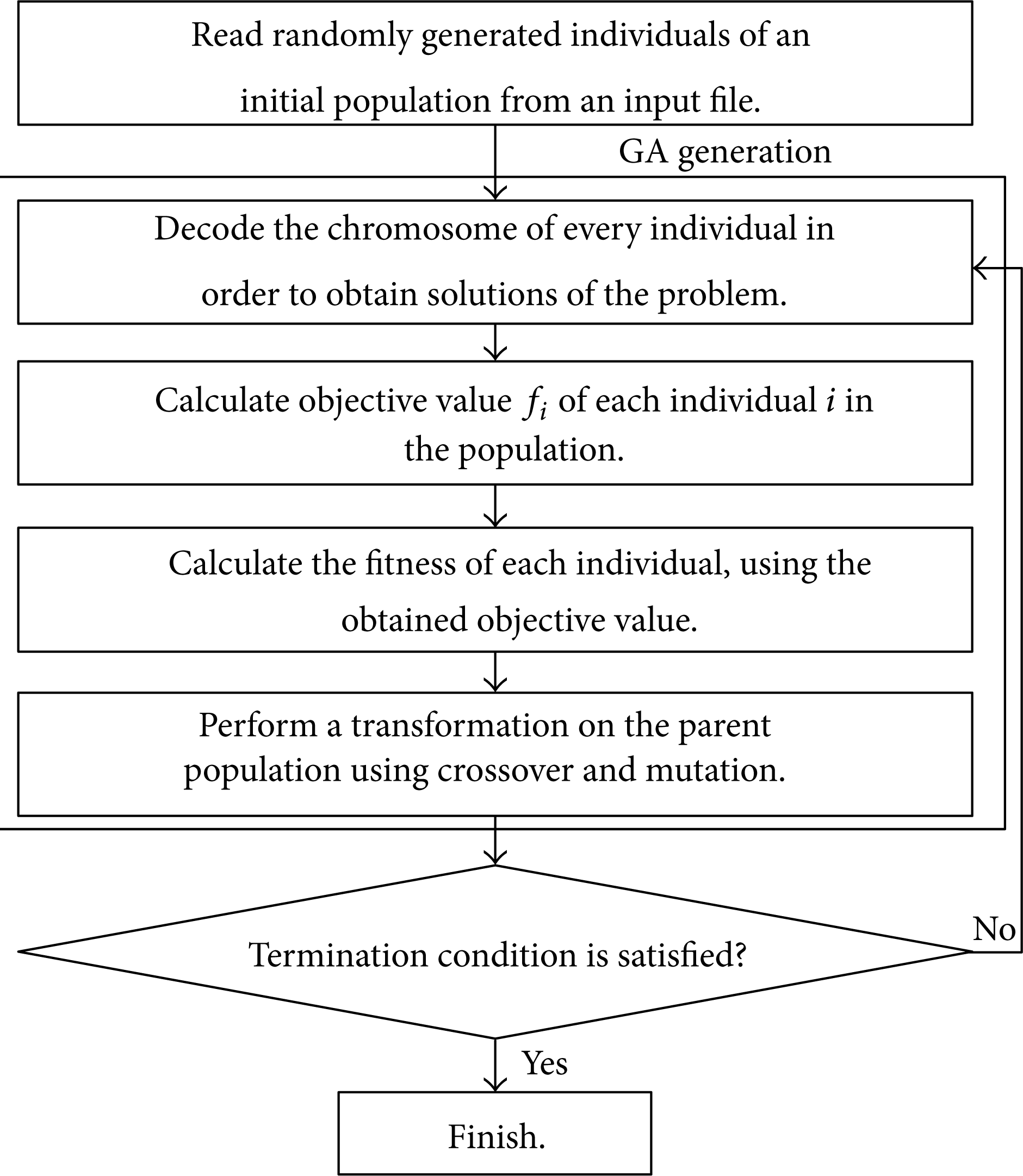
Main procedure of genetic algorithm.
By adding the elitism operator, after (4), then a set of fit individuals might be kept without crossover and mutation and merged with the newly generated individuals from crossover and mutation in (6) to form the new population. The elitism operator is incorporated into a genetic algorithm in order to promote the survival of the best individual found. The most commonly used elitism is to pass the first n number of best individuals from the current generation to the next generation without crossover and mutation.
2.2. CCGA Procedure
The main procedure of the CCGA is as follows.
Read randomly generated individuals of an initial population from an input file.
Decode the chromosome of every individual in order to obtain solutions of the problem and calculate objective values of all individuals. The individual having the best objective is assigned to be the current best individual.
Start with species counter s = 1 and divide an individual in the initial population into a number of parts in which each part represents each species. The objective value of an individual in the initial population will be the initial objective value of a corresponding individual in each species. The fitness calculation and parent selection will be performed in order to obtain the resulting subpopulation of each species. The initial objective calculation of the CCGA in this paper is quite different from the original initial objective calculation by Potter and De Jong [25]. The initial objective calculation in this paper is proposed to reduce computational time for an optimization problem.
In the current species s, a corresponding full solution of an individual i is obtained by the combination of the individual i with the corresponding parts from other species of the best individual. The objective value of the individual i is equal to that of the complete solution. If the objective value of the complete solution is better than that of the current best individual, the best individual and its objective value are then updated.
Perform GA operators to the individuals in subpopulation of the current species s as (4) to (6) in the GA procedure; thereafter increase the species counter s = s + 1 and go back to (4) until the last species is finished.
Check termination condition. If the condition is satisfied, report the final best individual as the output solution, otherwise, restart species counter s = 1 and go back to (4). It is noted that one loop from (4) to (5) is called one generation of the CCGA run.
Figure 2 shows the main procedure of the CCGA of an optimization problem with 4 decision variables. In the figure, each species of the CCGA represents a decision variable.

Main procedure of CCGA of an optimization problem with 4 decision variables.
3. Calculation of Objective Function
This section demonstrates the methodology for computing the objective function. The calculation of objective function is adopted from [5, 6]. The equation of the motion of dynamics of a multidegree freedom system is given by

where [m] and [k] are (n × n) mass and stiffness matrices and {x} and {F} are (n × 1) displacement and applied force vectors.
The jth eigen equation associated with (1) is given by the following equation:

where λ j and {v j } are the jth eigen value and corresponding unit eigen vector, respectively.
In the finite element model of the structure, the matrix [k] can be represented as a sum of the expanded element stiffness matrices of all divided elements:

where
Similarly, the matrix [m] is a sum of the expanded element mass matrices of all divided elements:
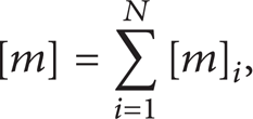
where
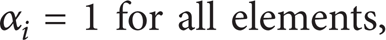
When damage occurs in a structure, stiffness matrix of the damaged structure [k d ] can be expressed as a sum of element stiffness matrices multiplied by stiffness factors associated with each of the N elements α i (i = 1, 2,…, N), resulting from the damage.
Then, the stiffness matrix of the damaged structure is given by

The values of the parameters fall in the range 0 to 1. The stiffness factor α i = 1 indicates that the element is undamaged and α i = 0 or less than 1 implies the completely or partially damaged element, respectively. The experimental natural frequencies and mode shapes represented by unit amplitude vectors of the damaged structure are approximated to satisfy the eigen equation, (2), of jth mode; therefore, the equation can be rewritten as
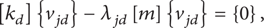
where λ jd and {v jd } are the approximated experimental eigenvalue and unit eigenvector of jth mode. Moreover, it is assumed that the mass matrix is unchanged due to the damage.
If β1,β2,…,β N are decision variables which are the predicted stiffness factors. By substituting the predicted stiffness factors into (1) and (2), an expression residual force vector of jth mode in a function of β i can be evaluated as follows:

The residual vector {R j } will be {0}, only if a correct set of β i , which shows that β i = α i for all i, is introduced under the experimentally damaged modal information λ jd and {v jd } for a particular mode j.
The (n × n) residual force matrix [R] is therefore obtained by
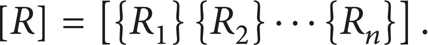
If all β i are correct, all elements of the matrix [R] must be 0. Unlike the previous works [5, 6] whose objective function is calculated from only diagonal terms of the residual matrix, in this paper, the objective function f of a set of predicted damage factors is evaluated from all elements of the residual matrix; f is represented by

where N is the number of elements and n is the number of degrees of freedom.
4. Test Problems
The damage detection of beams with three most commonly used boundary conditions—free end, simply supported (pinned) end, and fixed end—is employed in this paper. The cantilever (fixed-free ends) beams and simply supported (pinned-pinned ends) beams are used as the test problems. In addition, the test problems should consist of both uniform and nonuniform cross-section beams. Since the CCGA is capable for an optimization problem with a large number of decision variables, the beam with varied number of divided elements is required for the performance investigation of the CCGA. There are three test problems for the damage detection used in this paper—a uniform cross-section cantilever beam with 10 divided elements, a uniform strength cantilever beam with variation in width which represents for the nonuniform cross-section beam and is divided into 8 elements, and a uniform cross-section simply supported beam with the varied numbers of divided elements. The descriptions of the test problems are as follows.
4.1. Uniform Cross-Section Cantilever Beam
The damage detection in a uniform cross-section cantilever beam [5] as shown in Figure 3 is used as the first test problem. The beam is equally divided into 10 elements. The divided elements are numbered in ascending order, 1 to 10, from left to right of the beam as shown in Figure 3. There are 20 degrees of freedom—10 vertical displacements and 10 rotated angles, for the finite element model. The cross section of the beam is assumed to be a rectangle having the width (b) of 18.55 mm and the thickness (h) of 9.81 mm so that the cross-sectional area (A) and the area moment of inertia (I) are 1.82 × 10⁻⁴ m2 and 1.46 × 10⁻⁹ m4, respectively. The length (L) = 0.8 m, modulus of elasticity E = 70.3 GPa, and density P = 2,685 kg/m3.

Uniform cross-section cantilever beam.
Two different situations of this test problem are considered—(a) the beam is in a state of undamaged, and (b) the beam having elements 3 and 7 is damaged partially to an extent of 50% and 90%, respectively. Therefore, the actual stiffness factors α i for cases (a) and (b) are described by (10) and (11), respectively. The damage prediction of this problem is considered with no noise in the natural frequencies and mode shapes. Consider
4.2. Uniform Strength Cantilever Beam with Variation in Width
The second test problem is the damage detection in a uniform strength cantilever beam with variation in width [6] as shown in Figure 4. The material of the beam is the same as that of the beam in the previous test problem; hence, modulus of elasticity E = 70.3 GPa, and density ρ = 2,685 kg/m3. The thickness h is constant, but the width “b” linearly varies from b0 to zero. The thickness (h), the width of the cross section at the left end (b0), and the length (L) of the beam are equal to 0.01 m, 0.08 m, and 0.8 m, respectively.
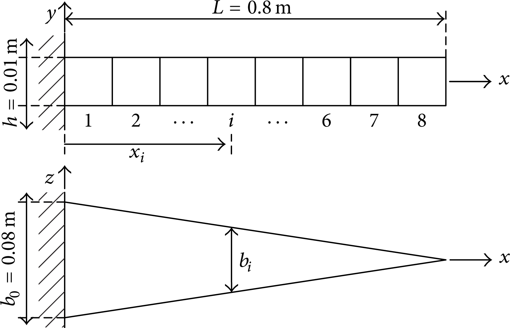
Uniform strength cantilever beam with variation in width.
The beam is divided into 8 elements with equal length so that there are 16 degrees of freedom—8 vertical displacements and 8 rotated angles, for the finite element model. The divided elements are numbered in ascending order, 1 to 8, from left to right of the beam as shown in Figure 4. The coordinate x i and width b i of the middle point of an element i are given by the following equations:

where N is the number of divided elements which is 8.
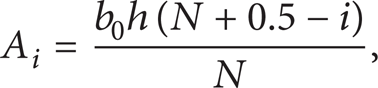
According to the previous work [6], the area (A i ) and moment of inertia I i of an element i were assumed to be the same as those of cross section of the corresponding middle point. Therefore, A i and I i can be evaluated by (13) and (14), respectively:

Hence, the expanded element matrices
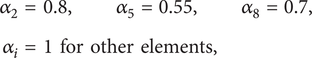
There are 4 cases of this problem—(a) the beam having no damaged elements (b) the beam having elements 3 and 5 damaged partially to an extent of 40% and 30%, respectively, (c) the beam having elements 2, 5, and 8 damaged partially to an extent of 20%, 45%, and 30% respectively, and (d) the beam having only element 6 damaged partially to an extent of 35%. The actual stiffness factors α i for cases (a)–(d) are then given by the following:
The noise in natural frequencies and mode shapes is considered in this problem, so that there are 2 conditions for the investigations—no noise in the vibration characteristics and random noise 2% in natural frequencies and 3% in mode shapes.
4.3. Uniform Cross-Section Simply Supported Uniform Beam with Varied Number of Elements
The damage detection in a uniform rectangular cross-section simply supported beam with varied numbers of divided elements (Figure 5) is proposed as the third test problem to investigate search performance of the CCGA. In this paper, MATLAB is used for numerical calculation of the objective function. The running time for the objective calculation in MATLAB is exponentially increased by the increment of the number of divided elements. Due to the limitation of the running time in MATLAB, the maximum number of divided elements should not be more than 300. There are 6 numbers of divided elements (N)—10, 20, 50, 100, 200, and 300. The divided elements are numbered in ascending order, 1 to N, from left to right of the beam as shown in Figure 5. Same as the beam used in the first test problem, the width (b) and thickness (h) of the cross-section are 18.55 and 9.81 mm. Hence, the cross-sectional area (A) and the area moment of inertia (I) are 1.82 × 10⁻⁴ m2 and 1.46 × 10⁻⁹ m4, respectively. The length (L) = 0.8 m, modulus of elasticity E = 70.3 GPa, and density ρ = 2,685 kg/m3.

Uniform cross-section simply supported uniform beam with varied number of elements.
Due to the occurred damage in the beam, the actual stiffness factor α i is linearly decreased from 1 to 1/N for an element i = 1 to N, respectively, where N is the number of divided elements. This factor α i is mathematically defined by the following equation. As the first test problem, the noise in natural frequencies and mode shapes is not considered in this problem:


5. Simulation Results and Discussions
The parameter settings of the CCGA for all test problems are illustrated in Table 1. A solution to each test problem is encoded by a real-value chromosome. The number of decision variables in the encoded chromosome is directly equal to the number of divided elements which is N. Each species represents a decision variable; the number of species is also equal to N. Only the number of decision variables (N) is different for any test problems as shown in Table 1.
Parameter settings of the CCGA for the damage detection of all test problems.

In the first problem, the number of generated solutions is equal to 10 × 20 × 25 = 5000; meanwhile 17000 solutions have to be generated in the case of standard GA used by the previous work [5]. The stiffness factors identified by the CCGA compared with those by the standard GA from the previous work for cases (a) and (b) of the uniform cross-section cantilever beam are exhibited in Tables 2 and 3, respectively. The stiffness factors obtained from the CCGA are almost the same as the actual stiffness factors for both cases. The solutions obtained from the CCGA are obviously better than those obtained from the standard GA, although the CCGA uses the smaller number of generated solutions. Figures 6 and 7 plot the predicted stiffness factors obtained from the CCGA versus the number of generated solutions for the cases (a) and (b), respectively. These figures show that the stiffness factors searched by the CCGA are quickly converged to the actual stiffness factors.
Identified stiffness factors for case (a) of the uniform cross-sectional cantilever beam.

Identified stiffness factors for case (b) of the uniform cross-sectional cantilever beam.


Graph of predicted stiffness factors obtained from the CCGA versus number of generated solutions for case (a) of the uniform cross-section cantilever beam.

Graph of predicted stiffness factors obtained from the CCGA versus number of generated solutions for case (b) of the uniform cross-section cantilever beam.
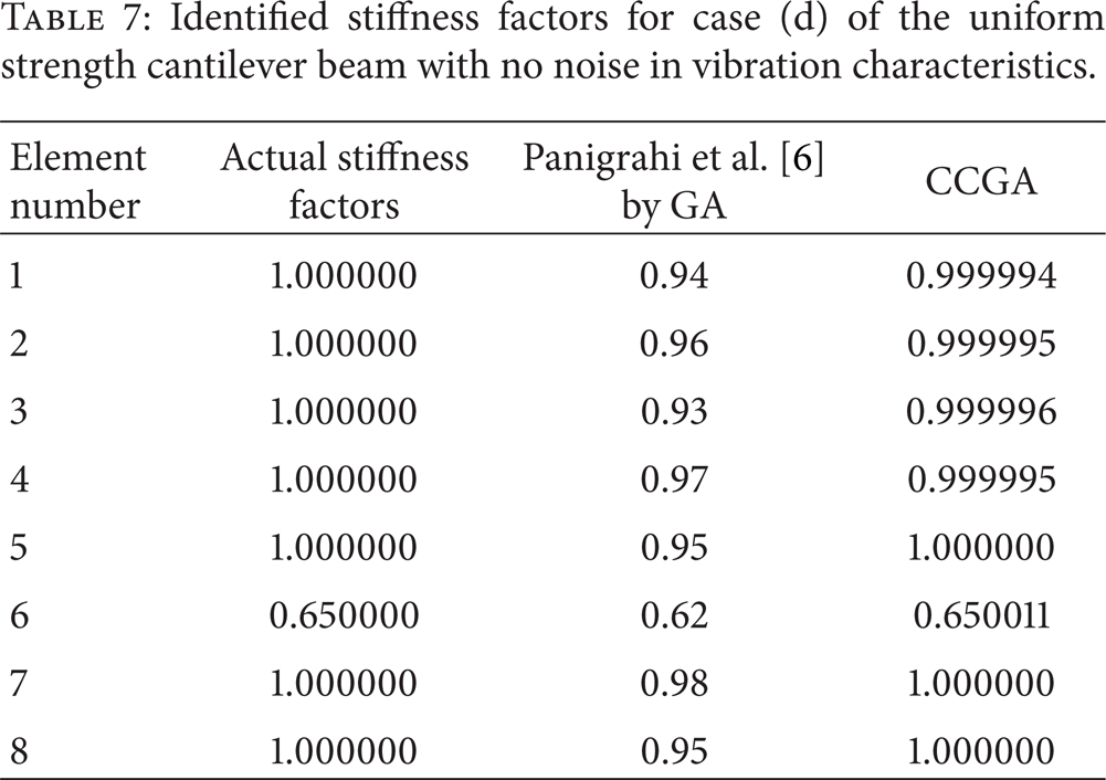
In the second test problem, the number of decision variables of this problem is different from that of the first problem. The number of divided elements is set as 8. The number of generated solutions for the CCGA is then equal to 8 × 20 × 25 = 4,000 which is much less than those of the standard GA, that is, 12000 solutions, used in the previous work [6]. The comparisons between the stiffness factors identified by the CCGA and those by the standard GA from the previous work for all cases of the uniform strength cantilever beam are shown in Tables 4, 5, 6, 7, 8, 9, 10, and 11. Similar to the first test problem, the stiffness factors obtained from the CCGA are superior to the solutions of the previous work for both conditions—without noise and with noise in natural frequencies and mode shapes. The predicted stiffness factors by the CCGA are almost the same as the actual stiffness factors for the cases without noise in the vibration characteristics as shown in Tables 4–7. Although there is the noise in natural frequencies and mode shapes, Tables 8–11 reveal that the stiffness factors obtained from the CCGA are quite close to the actual stiffness factors.
Identified stiffness factors for case (a) of the uniform strength cantilever beam with no noise in vibration characteristics.

Identified stiffness factors for case (b) of the uniform strength cantilever beam with no noise in vibration characteristics.

Identified stiffness factors for case (c) of the uniform strength cantilever beam with no noise in vibration characteristics.

Identified stiffness factors for case (d) of the uniform strength cantilever beam with no noise in vibration characteristics.
Identified stiffness factors for case (a) of the uniform strength cantilever beam with noise in vibration characteristics.

Identified stiffness factors for case (b) of the uniform strength cantilever beam with noise in vibration characteristics.

Identified stiffness factors for case (c) of the uniform strength cantilever beam with noise in vibration characteristics.

Identified stiffness factors for case (d) of the uniform strength cantilever beam with noise in vibration characteristics.

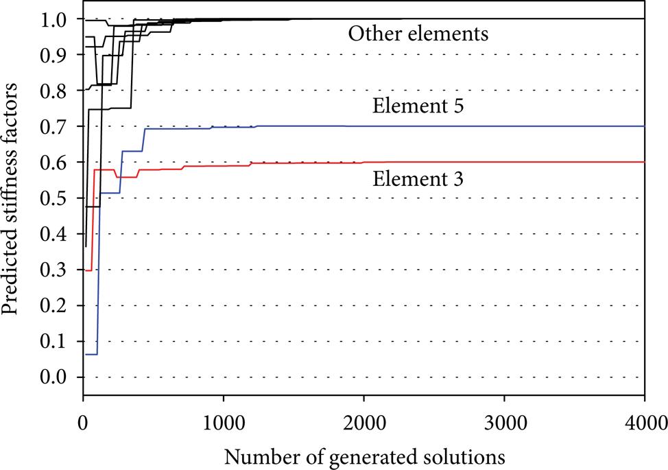
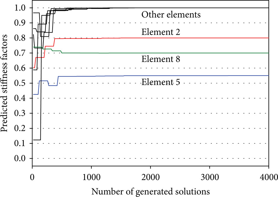
Figures 8, 9, 10, 11, 12, 13, 14, and 15 plot the predicted stiffness factors obtained from the CCGA versus the number of generated solutions for cases (a)–(d) without noise and with noise in the vibration characteristics, respectively. Similar to the first test problem, the stiffness factors searched by the CCGA are quickly converged to the good solutions including the cases that consider the noise in the vibration characteristics.

Graph of predicted stiffness factors obtained from the CCGA versus number of generated solutions for case (a) of the uniform strength cantilever beam with no noise in vibration characteristics.
Graph of predicted stiffness factors obtained from the CCGA versus number of generated solutions for case (b) of the uniform strength cantilever beam with no noise in vibration characteristics.
Graph of predicted stiffness factors obtained from the CCGA versus number of generated solutions for case (c) of the uniform strength cantilever beam with no noise in vibration characteristics.

Graph of predicted stiffness factors obtained from the CCGA versus number of generated solutions for case (d) of the uniform strength cantilever beam with no noise in vibration characteristics.

Graph of predicted stiffness factors obtained from the CCGA versus number of generated solutions for case (a) of the uniform strength cantilever beam with noise in vibration characteristics.

Graph of predicted stiffness factors obtained from the CCGA versus number of generated solutions for case (b) of the uniform strength cantilever beam with noise in vibration characteristics.
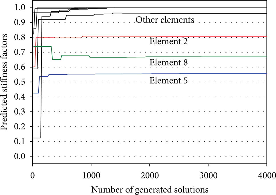
Graph of predicted stiffness factors obtained from the CCGA versus number of generated solutions for case (c) of the uniform strength cantilever beam with noise in vibration characteristics.

Graph of predicted stiffness factors obtained from the CCGA versus number of generated solutions for case (d) of the uniform strength cantilever beam with noise in vibration characteristics.
For the third test problem, the numbers of species of the CCGA, which are equal to the numbers of divided elements (N), are varied from 10 to 300. Since the number of species, the population size, and the number of generations are N, 20, and 25 respectively, the number of generated solutions is equal to N × 20 × 25 = 500N. Figures 16, 17, 18, 19, 20, and 21 show the comparison between the predicted stiffness factors obtained from the CCGA and the actual stiffness factors for all numbers of divided elements. The figures illustrate that the CCGA can correctly identify the stiffness factors in the beam regardless of numbers of divided elements.

Predicted stiffness factors obtained from the CCGA and actual stiffness factors of the simply supported beam with 10 elements.

Predicted stiffness factors obtained from the CCGA and actual stiffness factors of the simply supported beam with 20 elements.

Predicted stiffness factors obtained from the CCGA and actual stiffness factors of the simply supported beam with 50 elements.

Predicted stiffness factors obtained from the CCGA and actual stiffness factors of the simply supported beam with 100 elements.

Predicted stiffness factors obtained from the CCGA and actual stiffness factors of the simply supported beam with 200 elements.

Predicted stiffness factors obtained from the CCGA and actual stiffness factors of the simply supported beam with 300 elements.
6. Conclusions
The cooperative co-evolutionary genetic algorithm (CCGA) is proposed for an optimization problem with a large number of weak coupling decision variables. In this paper, the CCGA is implemented for detecting the damaged elements of the uniform cross-section cantilever beam, the uniform strength cantilever beam, and the uniform cross-section simply supported beam. The random noise in natural frequencies and mode shapes is considered in the uniform strength cantilever beam. In the simulation analysis, the CCGA provides the solutions that are better than the solutions of standard genetic algorithms employed by the previous works, although it uses the smaller number of generated solutions. Based on the results of the predicted stiffness factors, it is evident that the CCGA can effectively detect the occurred damage in the beams for all three test problems including the cases with the random noise in the vibration characteristics. This shows that there is low coupling strength between decision variables of the damage detection in the beams.
Moreover, the CCGA can efficiently solve the damage detection problems in beams with a large number of divided elements such as the beam with 300 divided elements demonstrated in the third test problem. For actual damage detection in beam that uses the measured experimental data such as [23, 24] instead of the approximated experimental results numerically evaluated by (6), the small number of divided elements could lead the search mechanism to the poor solutions due to the numerical errors in the objective calculation by the finite element model. Therefore, the large number of divided elements should be used in the actual damage detection. The CCGA, which is capable for an optimization problem having a large number of decision variables, is considerably suitable as an optimizer in the vibration-based damage detection in beams.
Conflict of Interests
The author declares that there is no conflict of interests regarding the publication of this paper.