
Abstract
The effects of the main operational machining parameters on the material removal rate (MRR) in abrasive waterjet turning (AWJT) are presented in this paper using a statistical approach. The five most common machining parameters such as water pressure, abrasive mass flow rate, cutting head traverse speed, workpiece rotational speed, and depth of cut have been put into a five-level central composite rotatable experimental design (CCRD). The main effects of parameters and the interaction among them were analyzed by means of the analysis of variance (ANOVA) and the response surfaces for MRR were obtained fitting a second-order polynomial function. It has been found that depth of cut and cutting head traverse speed are the most influential parameters, whereas the rotational speed is insignificant. In addition, the investigations show that interactions between traverse speed and pressure, abrasive mass flow rate and depth of cut, and pressure and depth of cut are significant on MRR. This result advances the AWJT state of the art. A complete model discussion has been reported drawing interesting considerations on the AWJT process characterising phenomena, where parameters interactions play a fundamental role.
1. Introduction
Abrasive waterjet turning (AWJT) is an innovative nontraditional machining technique which enables using advantages of waterjet in producing axisymmetric parts [1–5]. In the AWJT process, the workpiece rotates while the cutting head moves axially with an adjusted depth of cut (DOC) to produce the required geometries (Figure 1). The AWJT process has superior benefits in comparison with conventional turning. Material removal takes place by means of a flexible tool (abrasive waterjet), so AWJT is less sensitive to the workpiece shape, allows machining with high depths of cut in a single pass, and achieves higher material removal rates (MRRs) especially for hard to machine materials [5]. The process involves low cutting forces, so it is not affected by the workpiece length-to-diameter ratio and therefore it can turn long parts with small diameters [6]. Since employable abrasives could erode any materials, this process is ideally suitable for cutting materials with low machinability such as ceramics, composites, glass, and aerospace alloys [7–9]. Some attempts were previously made to study the AWJT process. Experimental investigations by the pioneer of this technique, Hashish, give very useful information about fundamentals for acquaintance of AWJT [1, 2, 10, 11]. As the first investigations, Hashish [1] discussed the effects of different parameters on the turning performance. Results illustrate the great potential of AWJT to produce near-net-shape parts at fast material removal rates. A visualization study [10] pointed out how the material removal takes place at the workpiece face and the process involves a mechanism of step formation and removal similar to the linear cutting with abrasive waterjet. Moreover, the observations suggest that the abrasive waterjet does not undergo any significant radial deflection in the region where material removal takes place. This study is the main reference for researchers that are involved with AWJT modeling based on linear cutting models. In other studies [3], the same authors investigated the effects of abrasive mass flow rate, abrasive particle size, waterjet pressure, and orifice diameter on AWJT material removal rate based on a “one factor at a time” approach. This traditional experimental method forces the performance of extensive experiments to investigate the effect of several parameters; moreover, the obtained results are hard to apply for achieving an optimized process. Zhong and Han [4] studied the influence of workpiece rotational speed, jet traverse speed, nozzle stand-off distance, and abrasive mass flow rate on workpiece surface quality in AWJT of glass based on a one factor at a time approach. This method is not able to show the interaction effects among the process parameters. Axinte et al. presented AWJT as an efficient method to profile and dress grinding wheels and proved its technological and economical capability [5], even if they did not clearly define their experimental design. Regarding the initial jet impact angle (90° or less), Li et al. classified AWJT into “radial-mode,” where the jet axis intersects the workpiece axis and “offset-mode” AWJT [12] (Figure 1). They reported the advantages of the radial-mode AWJT over the offset-mode AWJT in terms of MRR capability, including maximum jet energy exploitation, high surface speed, possibility to apply a variety of jet tilt angles, and small stand-off distances. They investigated the effects of jet traverse speed, workpiece surface speed, water pressure, abrasive mass flow rate, and jet impact angle on the depth of cut, but their synergic effects (interactions) were not discussed. Some other researches focused on AWJT modeling. The presented models are capable of estimating the final diameter of turned parts [2, 6, 13, 14]. An analytical model introduced by Ansari [2] relates the volume swept by the combined specimen rotation and AWJ nozzle traverse in the unit time (defined as the volume sweep rate (VSR)) to the material removal rate. This model could predict the specimen final diameter for various sets of AWJT process parameters. In spite of the continuous variation of the impact angle during the workpiece diameter reduction, Hashish's analytical model does not consider the impact angle modifications. A different approach considering the varying local impact angle was presented by Manu and Babu [6] to predict the final workpiece diameter. However, their model is not able to accurately predict the final diameter for various traverse speeds. Moreover, when the impact angle tends to zero, their model overestimates the removed material volume. By applying Hashish erosion model, Zohourkari and Zohoor presented a model with better results in terms of final diameter prediction [14, 15]. The presented analytical models do not consider reduction of jet energy utilization at depths of cut lower than the jet diameter, jet spreading, abrasive fragmentation, exact material flow stress, nozzle wear, and so forth that play a fundamental role in the material removal. Analytical models are still in their early stages and must be developed to become practical. Thus, statistical models which are capable of including the effects of controllable and uncontrollable parameters can be more powerful to model AWJT process.
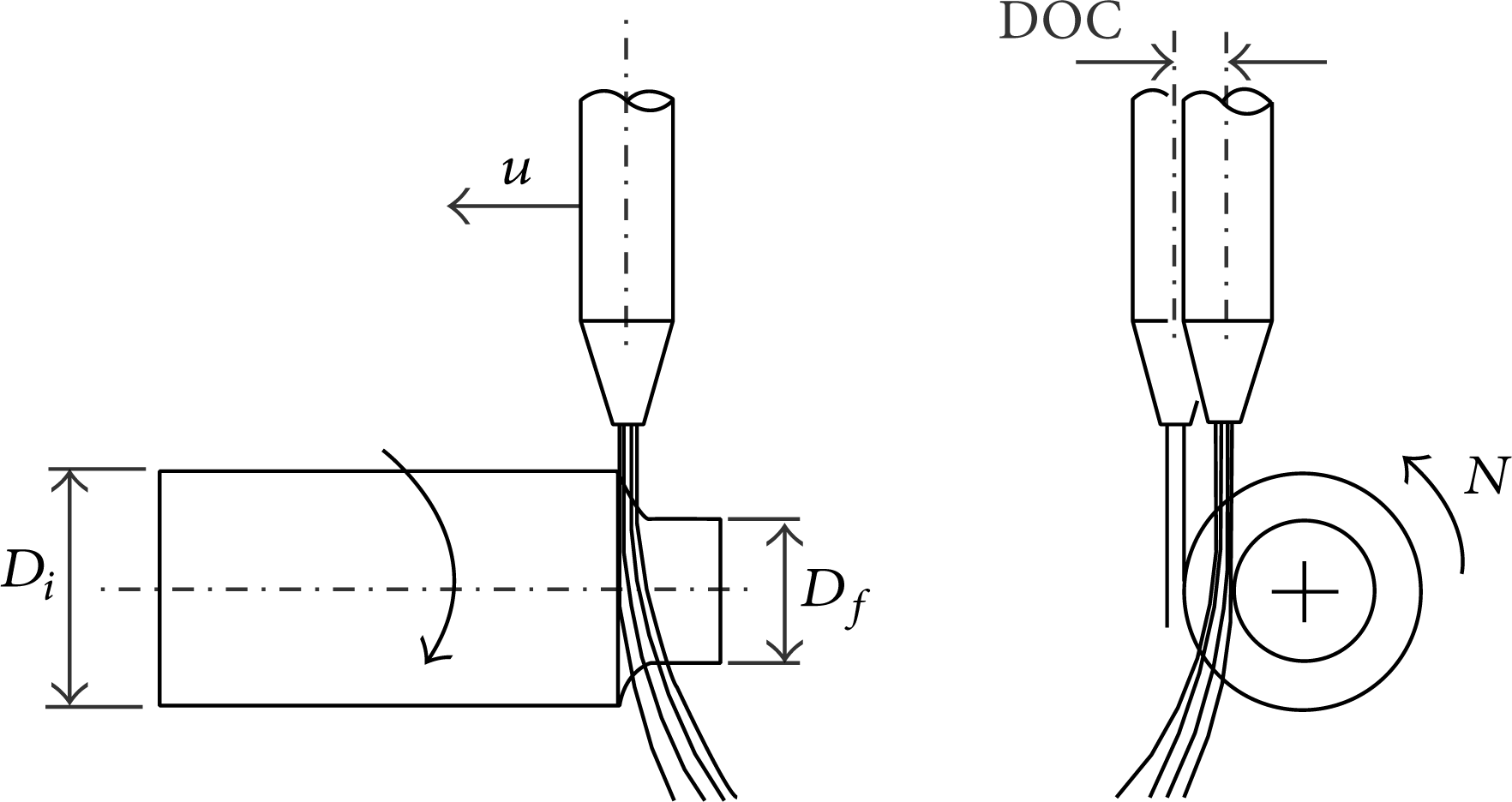
Schematic of AWJ offset-mode turning process.
To accurately model AWJT and to develop its technological and economical capabilities, it is important to investigate the process responses and side effects with respect to process parameters variations and find techniques to control them. To achieve this goal, it is necessary to find significant parameters and interactions playing a substantial role in the material removal rate, workpiece surface roughness, waviness, roundness, and geometrical errors. Up to now, a lack of such a systematic experimental study on AWJT is sensible; therefore abrasive waterjet offset-mode turning of AA2011-T4 alloy has been investigated in the present paper in terms of material removal rate. Five machining parameters such as water pressure, abrasive mass flow rate, cutting head traverse speed, workpiece rotational speed, and depth of cut have been considered in a five-level statistical experimental design and 52 experiments have been carried out based on a central composite rotatable design (CCRD) [16]. The machining parameters main effects and interactions have been analyzed by analysis of variance (ANOVA) technique and the MRR response surfaces have been obtained using a second-order polynomial. This work aims to obtain a valuable understanding of parameter effects in the abrasive waterjet offset-mode turning process and presents a statistical model useful for optimisation purposes.
2. Abrasive Waterjet Turning Strategy
Based on the relative position between jet and workpiece, AWJT is divided into radial-mode and offset-mode turning. An advantage of offset-mode turning compared to radial-mode turning is the ability to control the depth of cut [12] and to achieve better surface qualities [1, 4, 17]. Hence, AWJ offset-mode turning has been chosen for this study since it seems more capable of answering to industrial requirements. The schematic of the AWJ offset-mode turning is shown in Figure 1. In this process, the abrasive waterjet is adjusted in a desired position defining the nominal depth of cut (DOC) with respect to the reference tangential position. The workpiece rotates at the rotational speed N while the abrasive waterjet moves along the workpiece rotation axis at the traverse speed u and erodes the workpiece surface in a single pass to the final diameter (D f ). Workpiece rotates in the same verse as the AWJ for obtaining a better surface quality [1].
3. Abrasive Waterjet Turning Experiments
The abrasive waterjet turning experimental apparatus is based on a Tecnocut 5-axis handling system, a Flow 9XV-S 380 MPa pump, and a custom-built lathe device with maximum rotational speed equal to 1000 rpm (Figure 2).

The experimental set-up for abrasive waterjet turning.
30 mm diameter AA2011-T4 circular bars have been selected for the tests. All the parts were cut to a 100 mm length and carefully cleaned with ethanol alcohol. The AA2011-T4 composition is given in Table 1.
AA2011-T4 composition.

Mesh number 80 Australian garnet is used as abrasive. A standard 0.3 mm diameter orifice and a standard 1.02 mm diameter focusing tube have been selected for all the tests.
To obtain the required workpiece geometry, it is important to accurately adjust the DOC. The reference system applied to set the DOC at each experimental run has been defined by carrying out an accurate workpiece alignment procedure allowing the jet traverse speed to be parallel to the workpiece axis and the jet to be tangent to the workpiece surface. Low water pressure has been used during such a procedure in order to obtain a very thin and coherent jet passing along the specimen.
3.1. Experimental Design
The range of the selected parameters, that is, water pressure (P), abrasive mass flow rate (
The distance of the axial points from the center point (also called middle level) is determined by the α value. For a CCRD, α = n F 1/4. According to the number of factors in this study (k = 5), the α value is equal to 2.378 and the total amount of experiments is 52.
The experimental parameters are given in Table 2. Higher and lower levels of the corner points were, respectively, coded with + 1 and −1; the center points were coded with 0 and higher and lower levels of axial points were coded with + α and -α correspondingly.
Experimental design.
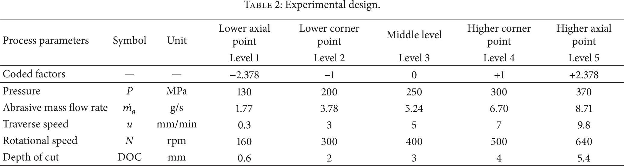
The linear relationship between coded and actual values in Table 2 is given in equations from (1a) to (1e) as follows:


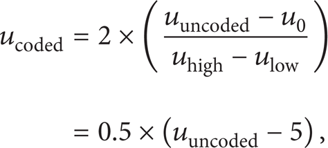
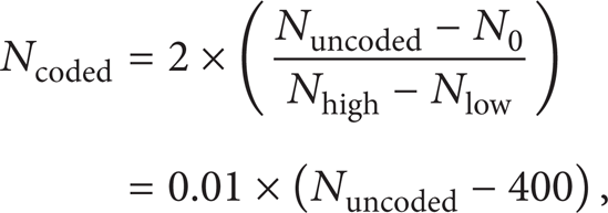
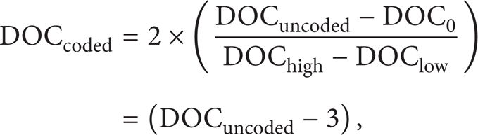
where subscripts “high” and “low,” respectively, represent the corner point high and low levels and subscript “0” indicates the center point.
The initial and final diameters, respectively, D i and D f , have been measured by means of a Zeiss Prismo 5 HTG VAST coordinate measuring machine (Figure 3) and MRR has been calculated according to


(a) Abrasive waterjet turned parts and (b) measurement of parts diameter by a Zeiss Prismo 5 HTG VAST CMM.
4. Response Surface Modeling
Response surface methodology (RSM) is a method to find a mathematical form of the relationship among the process responses and the process parameters using statistical and mathematical techniques [16, 18–20]. The mathematical equation stating the relationship between the AWJT process parameters and the MRR response can be expressed as

where f is the response function and x1, x2, x3, x4, x5 are, respectively, water pressure (P), abrasive mass flow rate (

where η is the approximated response and β ij are regression coefficients. The coefficients can be found by using the least squares method and linear regression analysis [16]. To obtain significant parameters, an analysis of variance is carried out. The significance level for defining significant parameters is typically set at 5% [21].
5. Results and Discussions
5.1. MRR Statistical Modeling
The turned parts obtained from the 52 planned experimental conditions (i.e., 32 corner points (n F = 32), 10 axial points (n a = 10), and 10 center points (n c = 10)) are shown in Figure 3.
The ANOVA results have been depicted in Table 3. As shown in this table, it can be concluded that the quadratic model is statistically significant, since its P-values is largely less than 0.05. Moreover, the null hypothesis for no lack of fit cannot be rejected (P-value higher than 0.05) which shows that no other predictors are required.
ANOVA table for the MRR regression model.
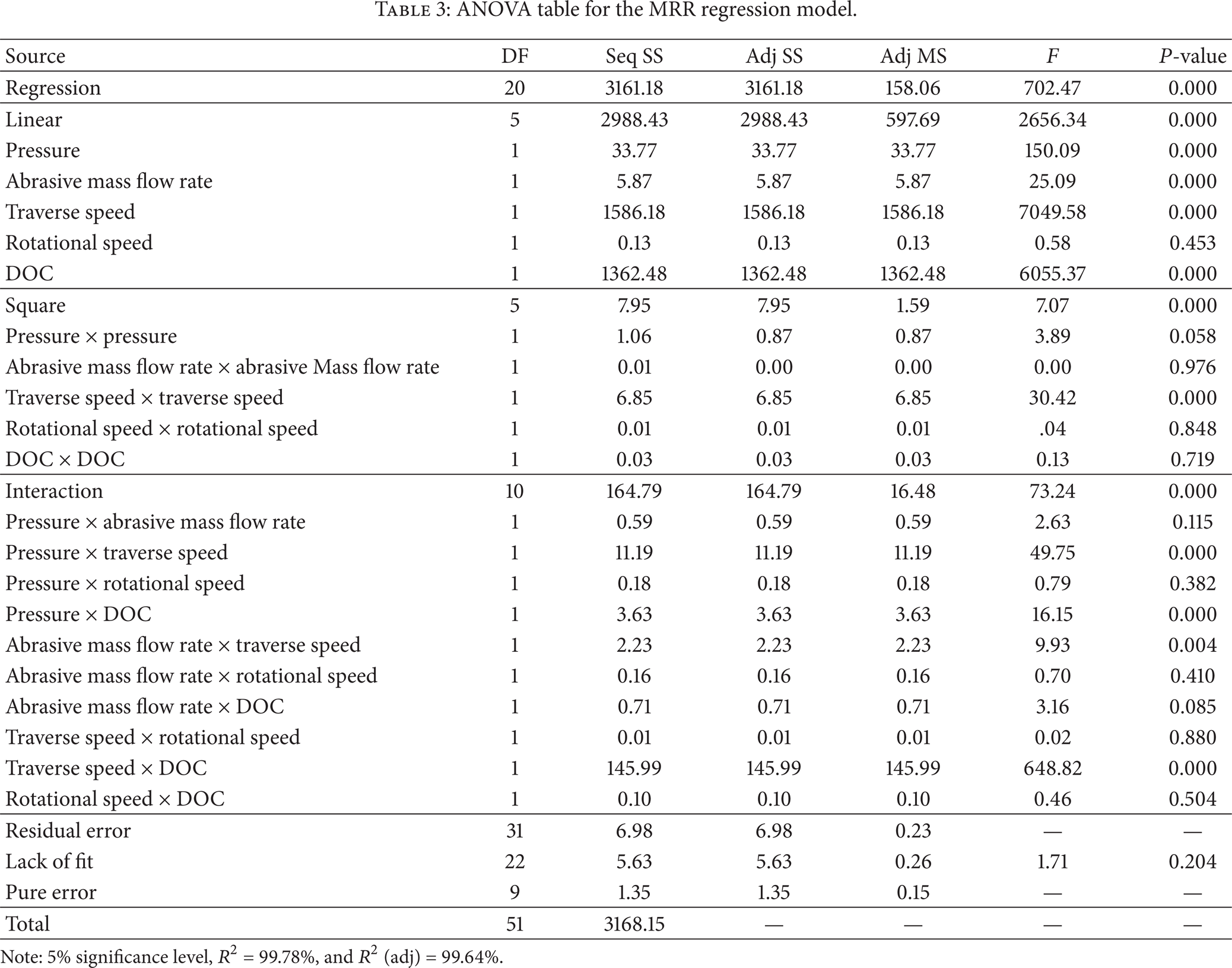
Note: 5% significance level, R2 = 99.78%, and R2 (adj) = 99.64%.
The calculated T-values along with the corresponding P-values are shown in Table 4. It has been found that pressure, abrasive mass flow rate, traverse speed, and depth of cut are significant and the rotational speed is insignificant. In addition, interactions between pressure and traverse speed, pressure and depth of cut, abrasive mass flow rate and traverse speed, and traverse speed and depth of cut are significant. The higher the P-value, the less significant the parameter; hence the interaction effect between abrasive mass flow rate and traverse speed places as last of significant effects. The other terms (P-value > 0.05) can be assumed to be insignificant.
T-test table results for the independent MRR model parameters.
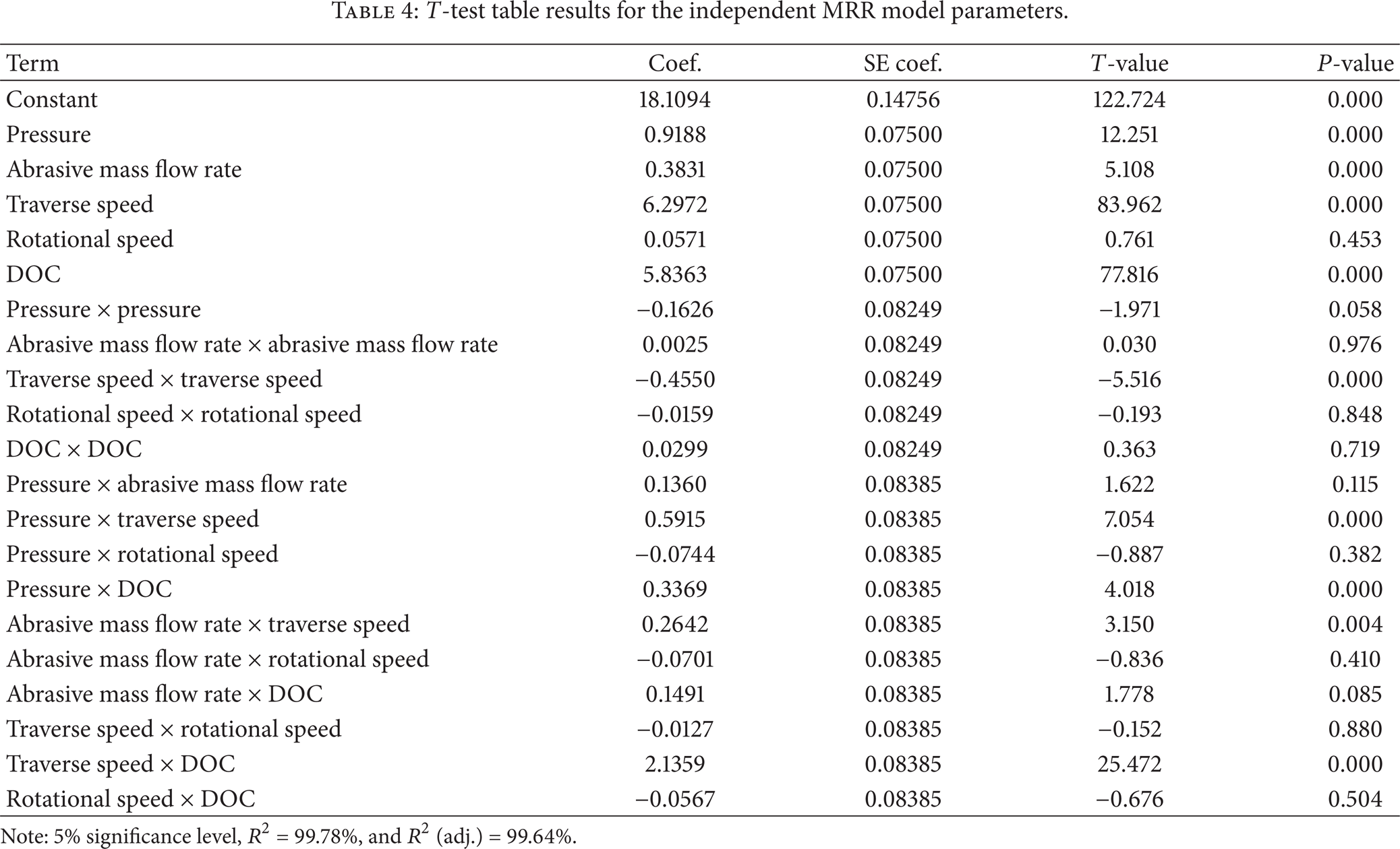
Note: 5% significance level, R2 = 99.78%, and R2 (adj.) = 99.64%.
The MRR model is given in
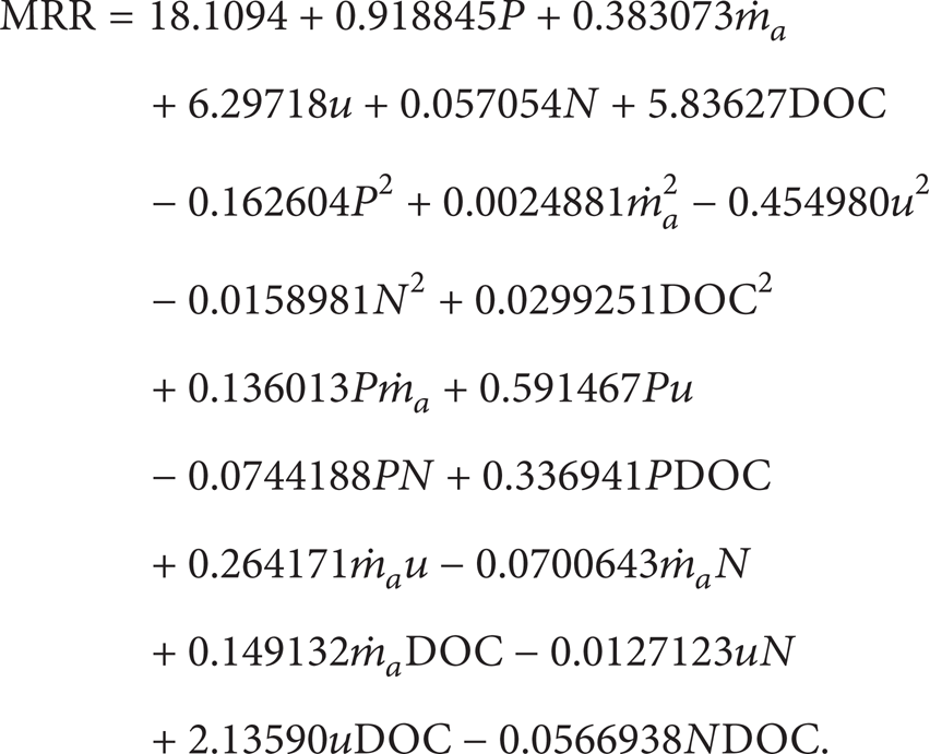
For the obtained MRR model, the R2 statistics indicates that 99.78% of the total variability is explained by the model, while the R2 (adj) that considers the number of model factors means that 99.64% of the total variability is explained by the model. The more the R2 approaches unity, the better the model fits the experimental data [16]. Moreover, since R2 (adj) is very close to R2, all the included factors are effective in terms of explanatory capability.
5.2. Investigation of the Effects of AWJT Process Parameters on MRR
The AWJT process parameters contribution to variability can be calculated from their sequential sum of squares (Table 3) and is given in Figure 4. It illustrates that u and DOC are the most influential parameters with percent contribution of 50% and 43%, respectively. Similar considerations on the process parameter weights on MRR can be drawn simply observing the factors coefficients in the MRR model: DOC and u, together with their interaction, have coefficients with an order of magnitude more than other factors. All the factors have been included in the model in this paper to increase the model prediction capability, but, in case the model simplicity was the target, only DOC, u, and their interaction could be considered. The sign of DOC, u, and u × DOC in (5) points out how these three factors play a positive role on MRR; that is, MRR increases if these factors increase. The same result for the effect of u and DOC has been reported by Ansari and Hashish [3].

AWJT process parameters percent contribution to variability.
More interesting MRR 3D surfaces and contour plots are illustrated based on the response regression equation in coded factors (see (5)). Effects of two factors are investigated at a time while other factors are kept constant at their middle level.
Figure 5 shows 3D surface and contour plot of the MRR response with respect to the traverse speed and depth of cut at constant levels of pressure (250 MPa), abrasive mass flow rate (5.24 g/s), and rotational speed (400 rpm). It illustrates that both the increase of traverse speed and depth of cut would increase MRR. Higher depths of cut introduce more volume of material to erode and higher traverse speeds reduce the machining time, thus leading to increasing MRR. In high depths of cut turning operation, higher MRR is achievable if the process is performed at high traverse speeds. This fact could be due to a most effective material removal on AA2011-T4 in case of curved cutting front, where erosion is more effective than abrasion, as it happens at high traverse speeds. At lower depths of cut, increasing the traverse speed is not so effective on MRR. In other words, at low depths of cut, the MRR does not increase at the same rate as at high depths of cut: at DOC = 2 mm (coded valu e= −1), a traverse speed increase up to 9.8 mm/min (coded value = + 2.378) improves MRR about 4 times, but, at DOC = 4 mm (coded value = + 1), MRR can increase more than 10 times.
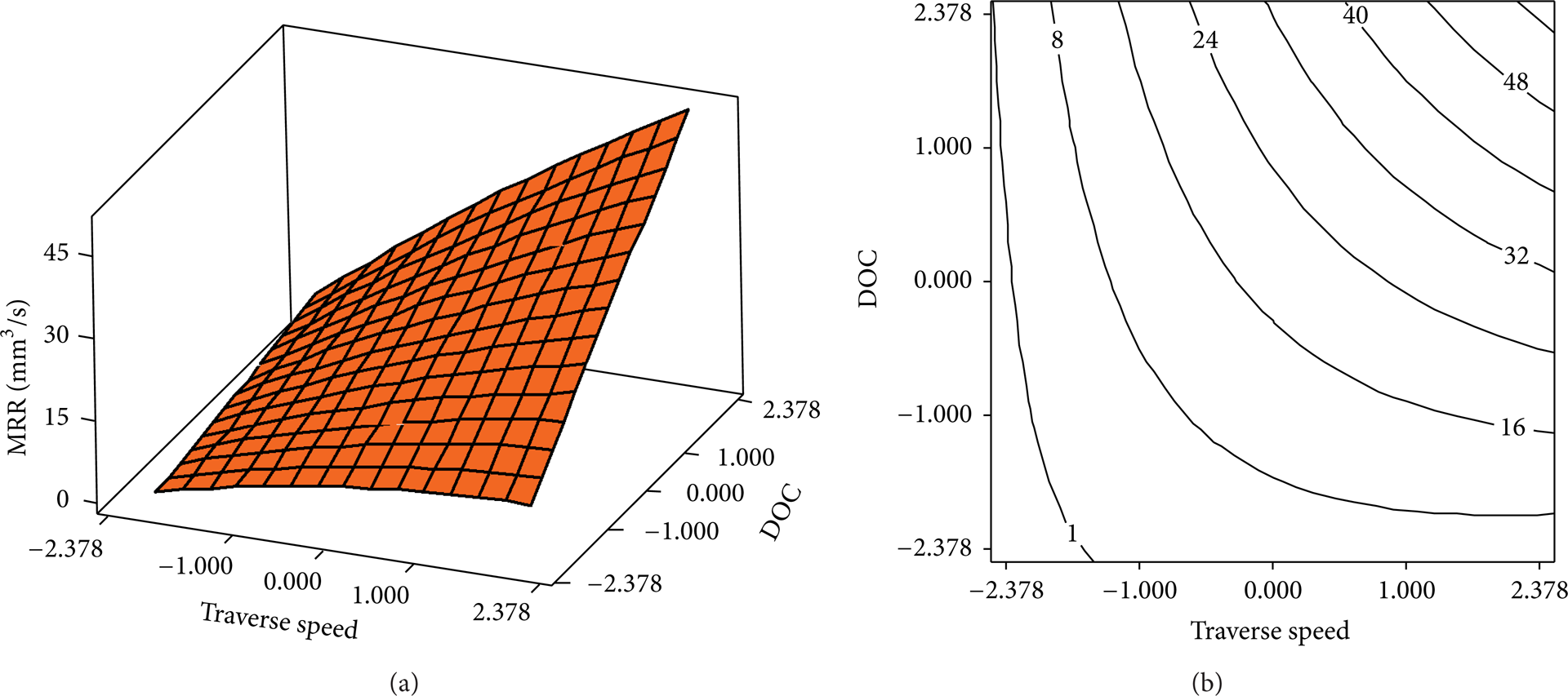
Effect of traverse speed and depth of cut on MRR (pressure = 250 MPa, abrasive mass flow rate = 5.24 g/s, and rotational speed = 400 rpm).
Figure 6 displays 3D surface and contour plot of the MRR response in relation to the abrasive mass flow rate and depth of cut conditions at constant levels of pressure, traverse speed, and rotational speed, respectively, fixed at 250 MPa, 5 mm/min, and 400 rpm. A plane surface showing positive upward inclination can be seen. The contour plot points out how the MRR gets higher as the depth of cut increases, while it is quite independent of the abrasive mass flow rate, as confirmed by the low value of its coefficients in (5). It is advisable to keep this parameter at low values to improve the process economic efficiency.

Effect of abrasive mass flow rate and DOC on MRR (pressure = 250 MPa, traverse speed = 5 mm/min, and rotational speed = 400 rpm).
Effects of abrasive mass flow rate and traverse speed on the MRR response are illustrated as surface and contour plot in Figure 7. The interactive nature of abrasive mass flow rate and traverse speed is more sensible at higher traverse speeds while, at lower traverse speeds, a change of the abrasive mass flow rate value does not influence MRR so much. It means that, at a low traverse speed, there is enough erosive power to properly carry out the turning operation, independently of the amount of abrasive. At high traverse speeds, instead, increasing abrasive mass flow rate positively affects the MRR, as more erosive power is needed in this case.
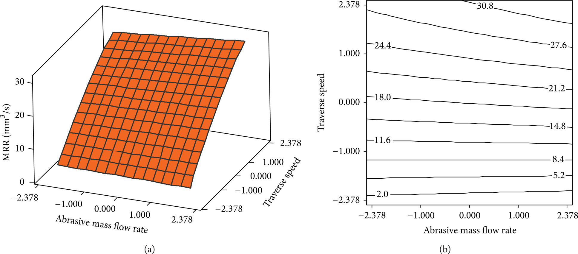
Effect of abrasive mass flow rate and traverse speed on MRR (pressure = 250 MPa, DOC = 3 mm, and rotational speed = 400 rpm).
Effects of pressure and depth of cut, while abrasive mass flow rate, traverse speed, and rotational speed are kept constant at their middle levels, are shown in Figure 8. It is concluded that higher MRR is achievable at high pressure and depth of cut. Additionally, the pressure effect on MRR is lower at low depths of cut: when pressure is increased in this case, it is possible to reach a point where no more material to erode is available. In other words, MRR does not exhibit a strong dependency on pressure at lower depths of cut because even low water pressures are able to erode almost the entire available volume of material.

Effect of pressure and DOC on MRR (abrasive mass flow rate = 5.24 g/s, traverse speed = 5 mm/min, and rotational speed = 400 rpm).
The simultaneous effect of pressure and traverse speed is shown in Figure 9. In general, it can be seen that increasing pressure and traverse speed increases MRR. Higher pressures produce more energy to accelerate abrasive particles, which results in higher erosion rates. At high traverse speeds, pressure is more effective because the reduced workpiece exposure time requires more erosive power to remove material.
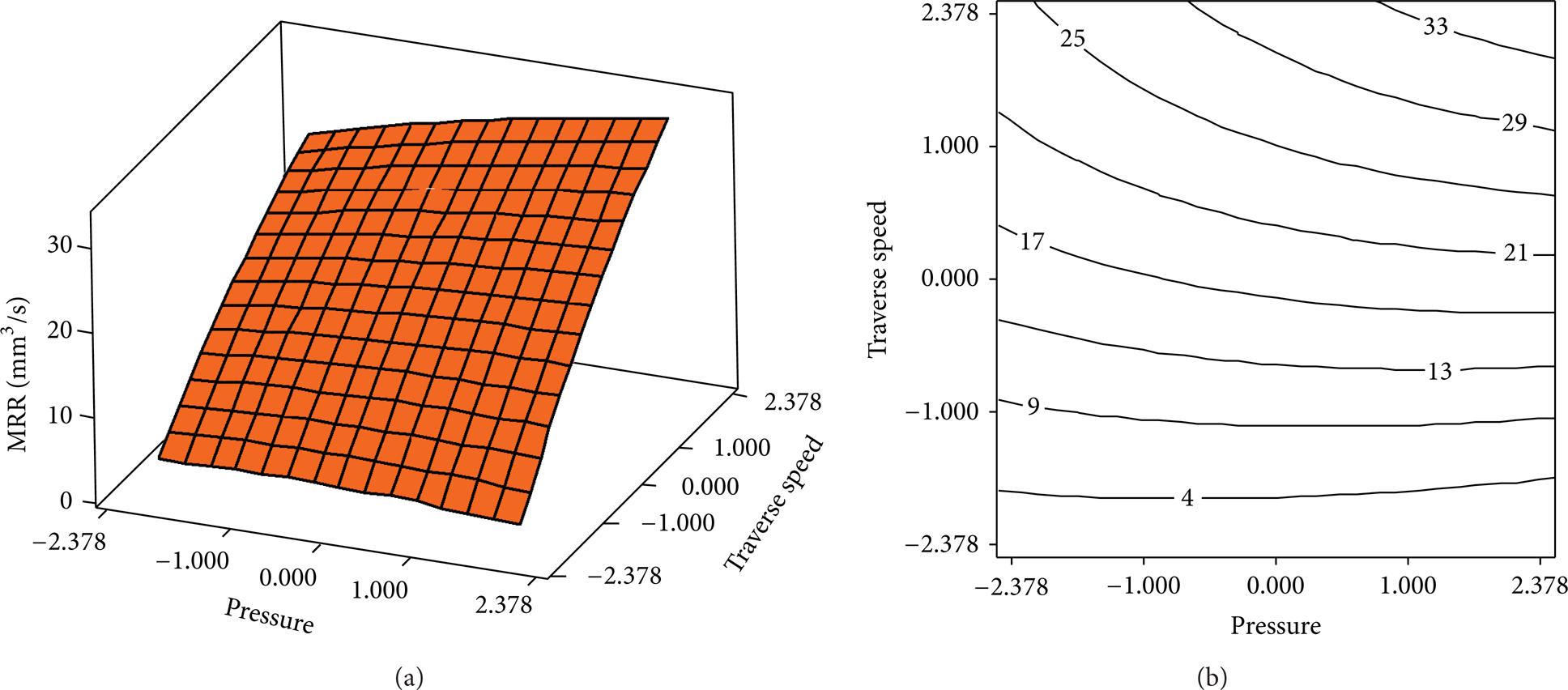
Effect of pressure and traverse speed on MRR (abrasive mass flow rate = 5.24 g/s, DOC = 3 mm, and rotational speed = 400 rpm).
Effects of pressure and abrasive mass flow rate on MRR, while other parameters are kept constant, are depicted in Figure 10. Increasing pressure and abrasive mass flow rate results in higher MRRs. In addition, pressure has more effect than abrasive mass flow rate on the MRR value, as it can be seen also from their coefficients in (5). Low pressures produce limited energy to accelerate the abrasives. So, increasing the abrasive mass flow rate at low pressures does not considerably affect MRR.

Effect of pressure and abrasive mass flow rate on MRR (traverse speed = 5 mm/min, DOC = 3 mm, and rotational speed = 400 rpm).
In order to qualitatively evaluate the possibility to extend the presented model to other materials, the effects of pressure and DOC on MRR are compared with results in [3] and are shown in Figure 11. It can be seen that trends predicted by the presented model for the AA2011-T4 alloy are similar to the AA6061-T651 trends reported by [3]. This fact indicates how some effects pointed out in this paper seem to be generalizable to other ductile materials.
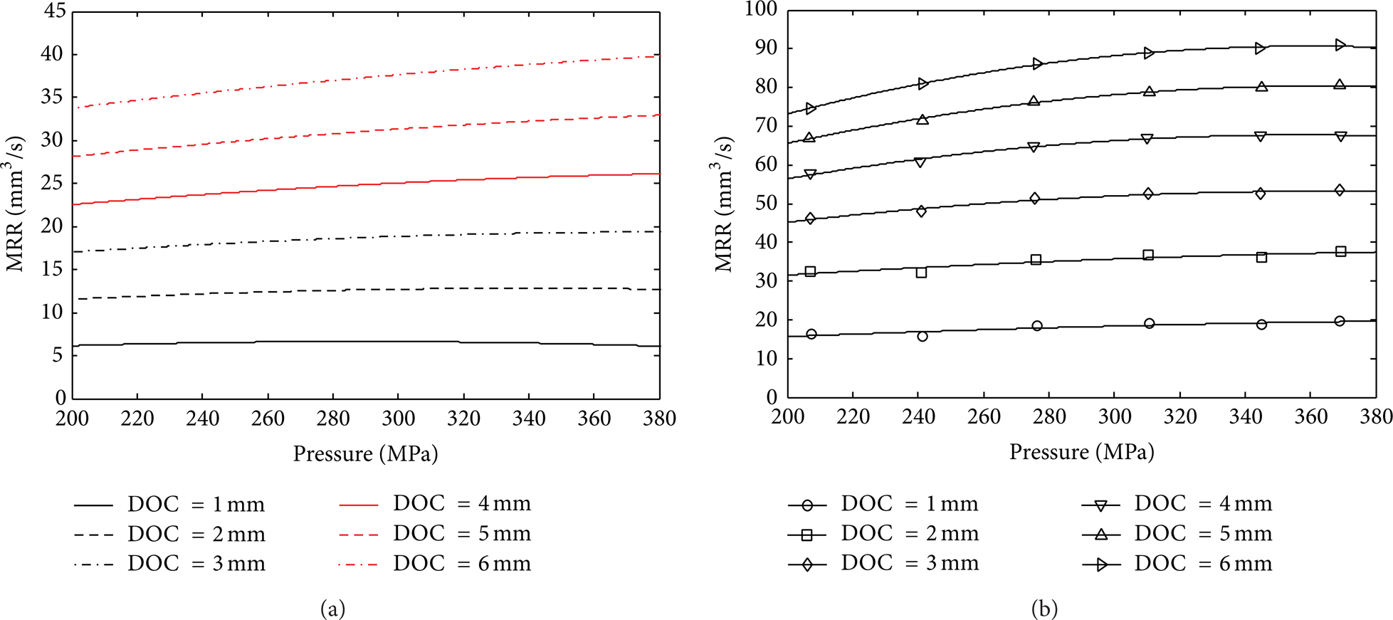
Comparison of the pressure effect on MRR at different DOCs (a) AA2011-T4 (abrasive mass flow rate = 5.24 g/s, traverse speed = 5 mm/min, and rotational speed = 400 rpm) and (b) AA6061-T651 (abrasive mass flow rate = 7.71 g/s, traverse speed = 12.72 mm/min, and rotational speed = 360 rpm) [3].
6. Conclusions
The effects of main operational machining parameters on material removal rate (MRR) in abrasive waterjet turning of AA2011-T4 have been investigated in this paper.
Distinctively from previous researches, a systematic experimental study on AWJT has been carried out which enables observing the effect of each parameter and its interactive effect on MRR. It has been found that, among the input process parameters, pressure, abrasive mass flow rate, traverse speed, and depth of cut are significant and rotational speed is insignificant. It must be noted that not only the main process parameters except rotational speed individually influence the MRR but also the interactions among them are influential. Second-order term of traverse speed and interaction between pressure and traverse speed, pressure and depth of cut, abrasive mass flow rate and traverse speed, and traverse speed and depth of cut are significant. The analysis shows that traverse speed and depth of cut are the most influential parameters with percent contribution to variability, respectively, equal to 50% and 43%, where simultaneous increase of them can increase MRR and vice versa. It is worth noting that pressure has interaction with depth of cut and traverse speed. So, the pressure level influences the increasing rate of MRR. The interactive effect of abrasive mass flow rate and traverse speed is also observable at higher traverse speeds while, at lower traverse speeds, a change of abrasive mass flow rate value does not influence MRR so much.
A model representing the relationship between the process parameters and MRR response has been obtained using the RSM approach. The model is useful for determining the most effective way to improve MRR. The model predictions have been found to be in good agreement with experimental data (R2 = 9 9.69% and adjusted R2 = 9 9.63%). As a confirmation of the model validity, the obtained relationships make sense under the physical point of view. Compared with other experimental data for AWJT of AA6061-T651, it showed that the MRR trend obtained from the presented model seems to be similar for other engineering materials.
This study also has shown that the CCRD and RSM could efficiently be applied to MRR modeling in abrasive waterjet offset-mode turning, obtaining the maximum amount of information in an efficient time and with the fewest number of experiments. However, further investigations are required to examine the material removal rate in relation to the workpiece surface quality and geometrical error. The knowledge of the effects of parameters and their interaction gives a worthy sight for further attempts to optimise the process and also model it more accurately. Other target materials will be studied in the future as further development.
Conflict of Interests
The authors declare that there is no conflict of interests regarding the publication of this paper.