
Abstract
Fermentation techniques are applied for the biotechnology and are widely used for food manufacturing, materials processing, chemical reaction, and so forth. Different fluids and types of blades in the tank for fermentation cause distinct flow and stress field distributions on the surface between fluid and blade and various flow reactions in the tank appear. This paper is mainly focused on the analysis of flow field with different fluid viscosities and also studied the stress field acting on the blades with different scales and shapes of them under specific rotational speed. The results show that the viscosity of fluid influences the flow field and stress distributions on the blades. The maximum stress that acts on the blade is increased with the increasing of viscosity. On the other hand, the ratio of blade length to width influences stress distributions on the blade. At the same time, the inclined angle of blade is also the key parameter for the consideration of design and appropriate inclined angle of blade will decrease the maximum stress. The results provide effective means of gaining insights into the flow and stress distribution of fermentation process.
1. Introduction
In recent years, study of fermentation system [1] is used for the development of biotechnology and also applied for the way of cultivating and producing acetone by tanks. The most common problem that arose at the initial stage of the culture was the contamination of the antibacterial bodies. Without the appropriate tanks, the ones with lids were used at the outset; they could not be used, however, to proceed with steam pasteurization under normal stress, so the kind of cylinder-shaped iron tanks with lids on the tops and semispherical bottoms were employed instead, and the pressurized steam-pasteurization was implemented. Pasteurization process also brought out the importance of sterilization of the cultured genes and seeds; the pipes, interfaces, and so forth must be sterilized, only then can the requirement of sterilization be met.
Application of appropriate fermentation tanks and fluids is the key to success during the process. Therefore, the design and choice of fermentation system have become highly significant. As far as the culture of microbes is concerned, the conditions of growth environment and the process should be treated differently according to different kinds of microbes; hence, the difference among the microbial systems should be taken into consideration when designing and manufacturing the fermentation tanks, so as to attain the optimal results under the suitable environment and conditions. Not only can the yield of microbes be greatly increased by the use of large-sized fermentation tanks [2], but the quality can be controlled to be stable with the steady provision of microbes and the time span of culture can be substantially shortened, which can help save both time and energy.
Fermentation process is the most extensively applied unit operation; the relations of which with the principles of hydrodynamics, thermal conductivity, chemical reactions, and so forth make it a complex existence. Fermenting can be applied to various and sundry production processes. In industries [3], for instance, it is utilized during the manufacturing process of numerous products to evenly separate the different chemical compounds to produce the assorted products that serve in different functions, such as adhesion and food products. The quality of products is influenced by the act of fermenting throughout the manufacturing process [4]; if it fails during the manufacturing process, the products will end up being unsatisfactory, discordant in quality, or unbalanced in constituents, which will not match up with our expectation.
It is also necessary for fermenting tank throughout the process considering convectional circulation, and diffusion [5, 6]. Also, there are some common requirements of fermentation process which are determined by characteristics of products. So, the analysis of blades, rotational speed, and the viscosity of fluid flow for flow and stress field will have different influences on different fermenting processes as well.
2. Geometric Design of the Fermentation System
2.1. Specification of a Fermentation Tank
The fermentation system employed in the experiment, as shown in Figure 1, includes a sealed cylindrical tank (without the passages that connect the inside and outside of the tank itself) whose diameter is 1.14 m long and the surface of the exterior wall is set to be nonslip. The relative specifications and the details of the dimensional parameters are shown in Table 1. The baffles and blades are placed symmetrically and the blade is set to rotate counterclockwise at the constant speed of 10 rpm for the simulation process.
Geometric parameters of a fermentation system.

Specification of the fermentation system.
2.2. Boundary Conditions
In this study, a cylindrical tank is used and shown in Figure 1. The inside wall of the tank is assumed as nonslip boundary. Table 2 shows the properties of three fluids including water, ethanol, and glycerin for numerical simulation. Table 3 shows the scales of blade for numerical simulation.
Properties of different fluids.
Scales of blade.
2.3. Governing Equations
The system governing equations are obtained by the transient continuity equation and momentum equations. They are nondimensionalized as follows.
The continuity equation such as (1) is shown as follows:
The fluid in fermenting tank is assumed as incompressible flow and ρ is a constant; then (1) is simplified in the following:

For the momentum equations are concerned in the x, y, and z directions of expression such as (3) to (5) and are shown below:
x-direction:
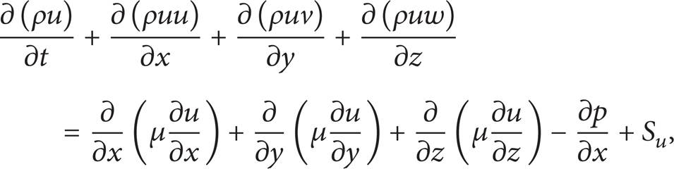
y-direction:

z-direction:

3. Numerical Results
3.1. Influence of Viscosity of Fluid
3.1.1. Impact on the System as the Fluid Is Water
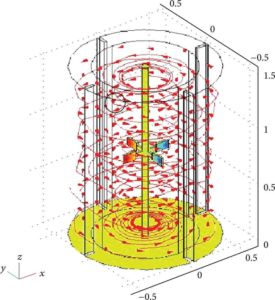
Figures 2 and 3 present the analysis of influence on the fermentation system as the fluid is water. When the blades rotate, the fluid is organized and divided into two streams up and down the field and is evenly distributed throughout the flow field as shown in Figure 2. From Figure 3, it shows that the stress on blades is negative, and the maximum absolute value is 4.352 × 10⁻⁴ pa. It is obtained that the maximum negative stress occurs on the edge and position of (−0.2, 0.7) in the YZ plane.

Flow field distribution of fermentation tank as the fluid is water.
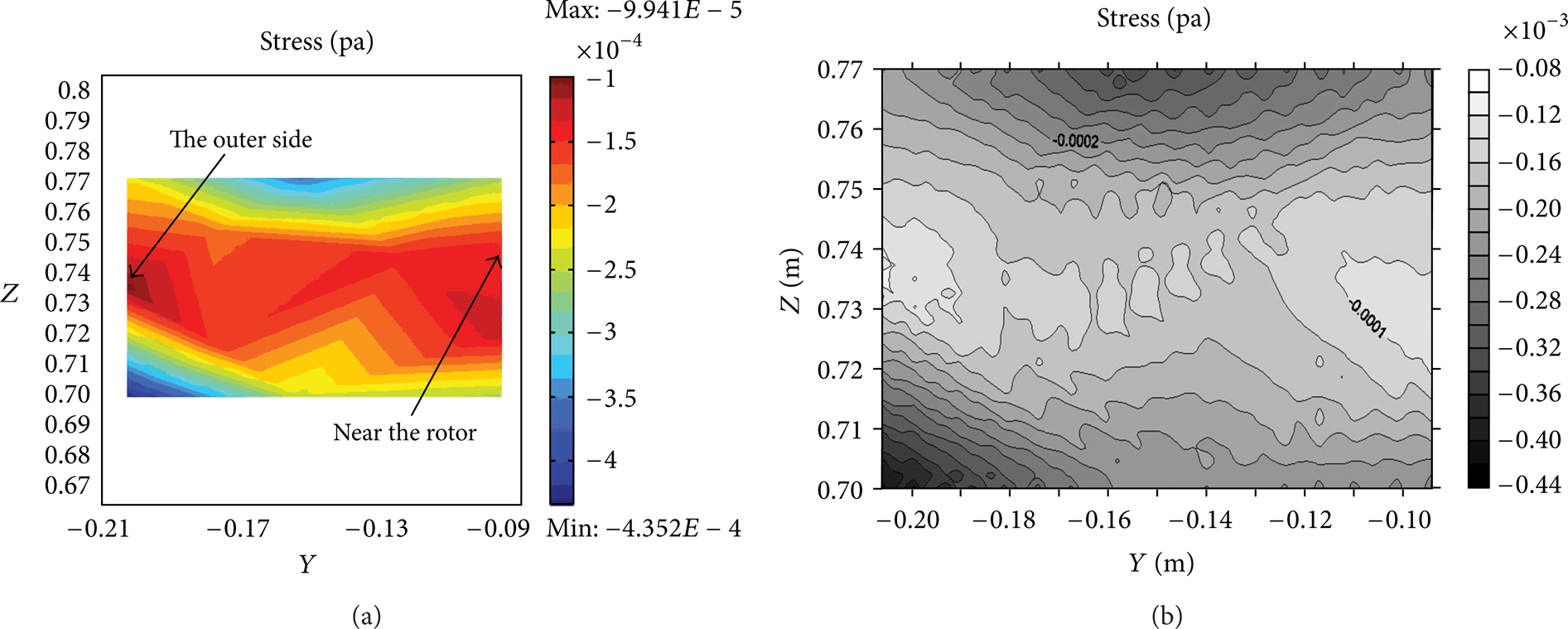
(a) Stress distribution and (b) stress contour map of blade as the fluid is water.
3.1.2. Impact on the System as the Fluid Is Ethanol
Figures 4 and 5 show the results about the analysis of alcohol. The mixing blades rotate to cause the same form as water in the upper and lower uniform flow field shown in Figure 4. Also, the maximum negative stress on the blade is reduced to 3.762 × 10⁻⁴ pa as shown in Figure 5. It is observed that the extreme stress appears at the area the same as the situation of water through Figure 5(b).

Flow field distribution of fermentation tank as the fluid is ethanol.

(a) Stress distribution and (b) stress contour map of blade as the fluid is ethanol.
3.1.3. Impact on the System as the Fluid Is Glycerol
Because the viscosity of glycerol is close to the real fluid of fermentation process, the simulations for the glycerol are studied and presented in Figures 6 and 7. When the blades rotate, the fluid flow field does not divide into upper and lower areas but produces a single flow field shown in Figure 6. The results are quite different from water and ethanol and also the stress on the blade is changed as positive value of maximum extremes of 0.14 pa as shown in Figure 7. However, the maximum stress regions occur in the vicinity of position at (−0.18, 0.75) in YZ plane. The extreme value does not appear in the blade edge as shown in Figure 7.
Flow field distribution of fermentation tank as the fluid is glycerol.
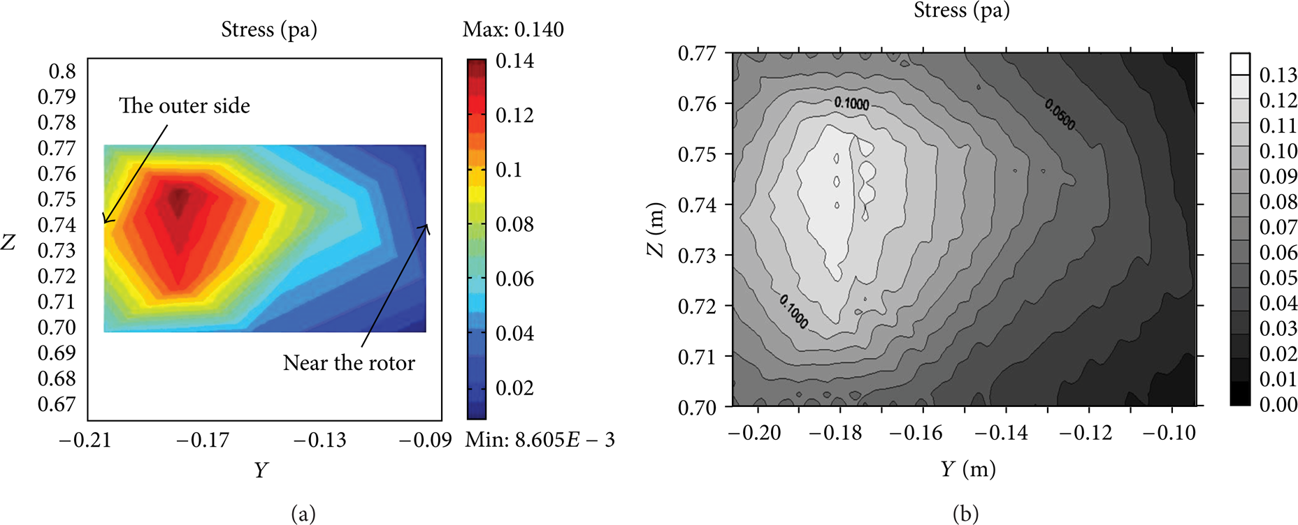
(a) Stress distribution and (b) stress contour map of blade as the fluid is glycerol.
3.1.4. Comparison of Stress Distributions for Different Fluids
From Figure 8, the data of results are obtained on the edge of the blade with coordinates from (0.094, 0.77) to (0.206, 0.77) and it is observed that the rotation of blades caused the larger stress generated by glycerol than those by water and ethanol. Also, the positive stress zone of glycerol is shown, but the value of stress decreased rapidly at the blade position −0.15 m.

Stress distribution generated by different fluids.
For three different fluids, it is obtained that the maximum stress on the blade is in the order of glycerol > water > ethanol. However, the stress distributions of water and ethanol are similar. The viscosity of fluid influences the stress acting on the blade and the larger of viscosity causes the greater stress.
3.2. Influence of Different Blades
3.2.1. Influence of Different Sizes of Blade-Fixed Length and Altered Width of Blade
Figure 9 shows us stress distributions of blade with different width of 0.015 m (R w = 7.5), 0.025 m (R w = 4.5), 0.035 m (R w = 3.2), and 0.045 m (R w = 2.5). In Figure 9, we analyze the stress generated onto the YZ surface of the blade, and the result shows that the absolute maximum stresses of these four cases are 3.975 × 10⁻⁴, 4.128 × 10⁻⁴, 2.831 × 10⁻⁴, and 3.381 × 10⁻⁴, respectively. Also, all maximum stresses occur at the outer side away from the rotor.

Distribution of stress in accordance with different widths of blade.
Figure 10 shows the stress distribution on the XY surface of blade with different R w and the stress data calculated from the coordinates of (0.094, 0.77) to (0.206, 0.77). The results reveal that absolute stress of R w = 7.5 and 3.2 decreases suddenly at Y = 0.14 m. But absolute stress of R w = 4.5 and 2.5 stabilizes from increasing situation at Y = 0.14 m. So, Y = 0.14 m is the key point of blade.

Stress curves with different values of R w .
3.2.2. Influence of Different Sizes of Blade-Fixed Width and Altered Length of Blade
Figure 11 shows stress distributions of blade with different length of 0.0975 m (R L = 6.5), 0.112 m (R L = 7.5), 0.1275 m (R L = 8.5), and 0.1425 m (R L = 9.5). In Figure 11, the stress is analyzed and generated onto the XY surface of the blade, and the result shows that the absolute maximum stress of R L = 6.5 is 0.125 which occurred at the interval of X [0.14, 0.16] away from the rotor and the same situation for R L = 8.5 is shown in Figure 11(c). But, the maximum stress transfer to X [0.13, 0.14] and the value decrease to 2.3 × 10⁻³ are shown in Figure 11(b). And when R L increases to 9.5, the maximum stress occurs at the outside of blade X [0.2, 0.22].

Distribution of stress in accordance with different lengths of blade.
Figure 12 shows the stress distribution on the outer side of blade with different R L and the stress data calculated from the coordinate of Y [−0.007, 0.007]. The results reveal that absolute stress of R L = 6.5 is the greater than all the other cases and the maximum absolute stress occurs at Y = −0.007.

Stress curves with different values of R L .
3.2.3. Influence of Different Inclined Angles of Blade
The inclined angle of blade influences the uniform situation of fermentor, and the thermal stress caused by the friction between blades and fluid is also influenced by the inclined angle of blade. Different inclined angles will induce different effects including reaction phenomenon, reactive heat, and thermal stress. So, it is necessary that the influence of inclined angle of blade should be analyzed and set up for the angles of 0°, 30°, 45°, and 60°. The rotor rotates with the speed of 10 rpm counterclockwise.
The results show that the stress that acts on the XZ surface is negative and the maximum value occurs at z = 0.68 as shown in Figure 13(a). As the inclined angle of blade is increased to 30° and 45°, the stress distribution exists in two different areas including positive and negative stress areas shown in Figures 13(b) and 13(c). When the angle is further increased to 60°, the stress distribution reveals that the minimum stress occurs near the rotor as shown in Figure 13(d). From Figure 14, the stress distribution under different angles shows that the blade induced the suddenly positive stress at X = 0.04 m and then decreased to cause negative stress at X = 0.08 m, when the angle is equal to 60°. For the other three cases, the stress distributions are more stable and it is obtained that the larger inclined angle will cause the more variation.
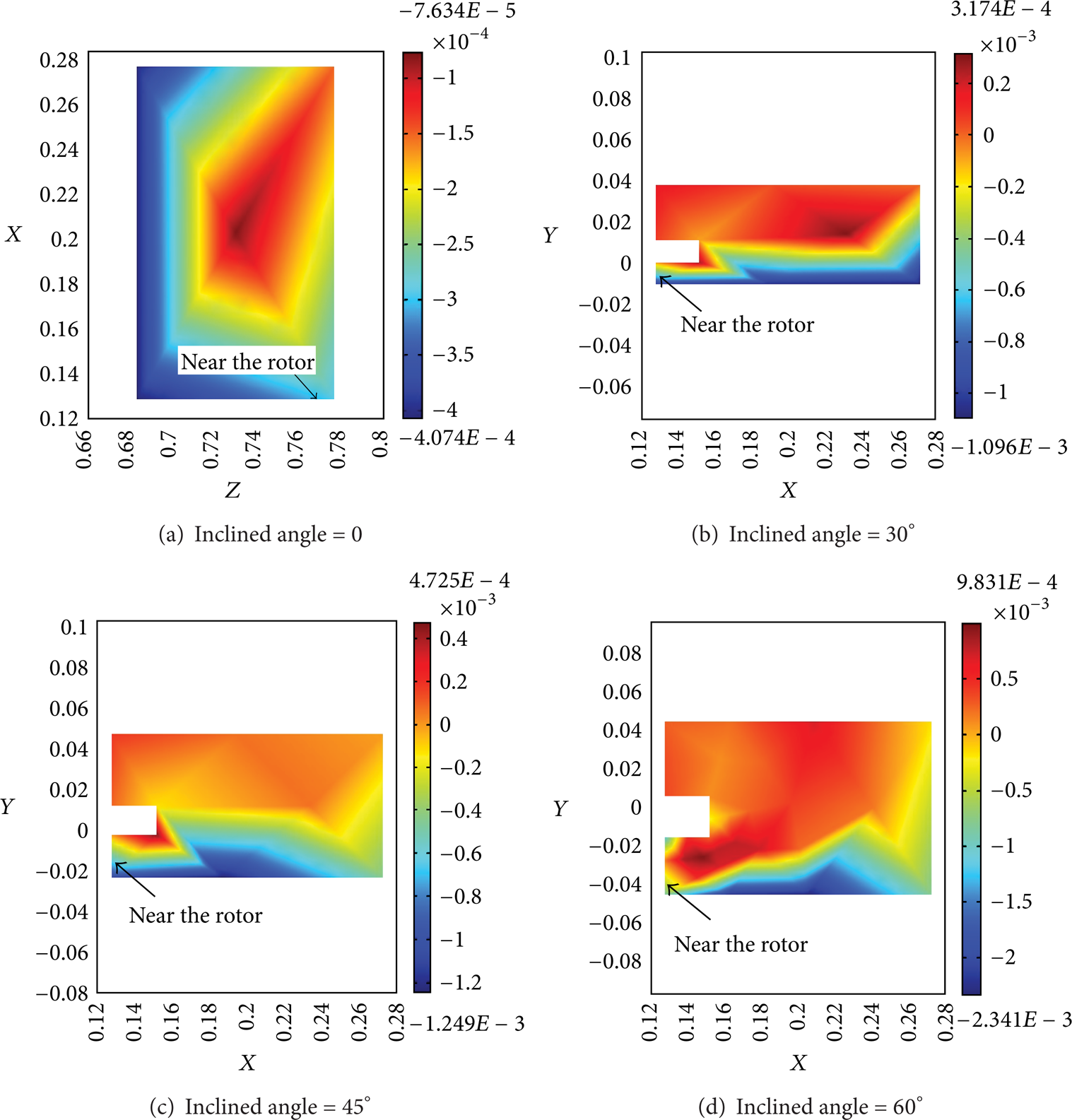
Distribution of stress in accordance with different inclined angles of blade.
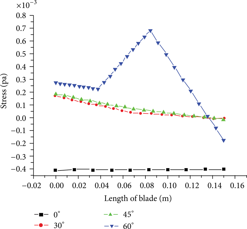
Stress curves with different inclined angles of blade.
4. Conclusion
From the simulation results, it is shown that the fluid flows by rotating of the blades. As the fluid flow hits the wall, it causes a stationary point and then transfers to be the axial flow. While the stagnation occurs, the stress appears under this situation and the formation of the upper and lower circles is produced as well.
It is obtained that the maximum stress acting on the blade for three fluids behaves in the order of glycerol > water > ethanol. However, the stress situations of water and ethanol are similar. The viscosity of fluid influences the stress acting on the blade and the larger of viscosity the greater stress caused.
It is also shown that the scales of the blades influence the stress distribution induced by fluid for a fermentation process. As the fluid flow hits the blade, it causes different types of stress areas under specified parameters of blade scales. While the R w is increased, it does not mean that the absolute stress is increased. But, it is interesting that the stress varies suddenly at Y = 0.14 m for all cases. The maximum stress acting on the blade for lower R L of the blade is also obtained. And, for considering the influence of inclined angles of blade, the stress variations acting on the blade are increased for larger angles.
The numerical results can be the guideline for the design of fermentor in a fermentation process to prevent the thermal stress induced by inappropriate blade scales.
Conflict of Interests
The authors declare that there is no conflict of interests regarding the publication of this paper.
Footnotes
Acknowledgments
The financial support of this research by the National Science Council of Taiwan, under Grants NSC-98-2622-E-269-004-CC3, NSC-102-2221-E-167-035, and NSC-102-2622-E-167-013-CC3 is greatly appreciated.