
Abstract
A novel hybrid antilock braking system (ABS) with the combination of auxiliary brake and a multipole magnetorheological (MR) brake was proposed in this paper. The MR brake with innovative operation concept can replace existed hydraulic brake system or works as an auxiliary brake. Two simulation models of the MR brakes, inner rotor and outer rotor structures, have been built. The outer rotor design was chosen due to its better braking performance and suitable mechanism for using on motorcycle. After that, motorcycle simulation software was employed to validate the hybrid ABS system under appropriated working condition. Two controllers, the ordinary and self-organizing fuzzy logic controllers (FLC and SOFLC), were evaluated on ABS performance to pick the suitable one. Simulation results confirm the more adaptations to different road conditions of the SOFLC with 18% higher brake performance compared to ones of ordinary FLC. Brake performance can increase 12% more with the combination of SOFLC and road condition estimator (RCE). It is concluded that this hybrid ABS is feasible for actual application by effectively improving the brake performance for ensuring driving stability.
1. Introduction
A vehicle in braking is very easy to slip on wet roads because their tires are often locked by brake system. Antilock brake system (ABS) is very effective to avoid brake locking and the consequent accidents. It also significantly reduces braking distance to enhance driving safety. The conventional antilock braking system (ABS) in motorcycle uses a hydraulic system, consisting of controlled pump, a well-known ABS controller, and an on-off valve, to apply/nonapply the braking force to the brake disc [2]. The control of the ABS commonly depends on the on-off frequency of the on-off hydraulic control valve, which determines the ABS performance. It is limited by the slow response and low switching frequency of the hydraulic system.
In the meantime, magnetorheological (MR) brake applications have caught major concern from researchers since the invention of MR fluids in 1940s [3]. Since 1997, the world's first commercial MR rotary brake has been produced by Lord Corporation as the RD-2085-01 MR [4]. However, its lack of powerful torque still challenges researcher to the further development. Karakoc et al. [5] have compared the MR brake with the conventional hydraulic brake and pointed out that the MR brake reduces actuation delay, has ease of software control implementation, and cuts down the system weight. As conclusion, the major advantage of MR brake is the controllable brake torque with fast response and large range by changing the strength of magnetic field while maintaining a lower cost of system. The properties and behavior of the brake will be easy to adapt by simply changing software parameters and electrical outputs instead of adjusting mechanical components. From the large, controlled yield stress that the MR fluid is able to achieve, the brake presents high controllability, fast response time (<25 ms) (which is faster than that (50 ms) of conventional hydraulic brake system [6]), and a wide torque range [7]. Moreover, its low electric power requirement compared to eddy current brake gives more space for financial investment in mechanical system. In vehicle engineering, the brake-by-wire MR brake replaces the mechanical connection between the brake actuator on each wheel and the brake pedal with electrical components. MR brake devices also have other benefits such as programmable functionality, easy integration and maintenance, rugged construction, and long service life [8]. Diagnostic features and the free of water polluting brake fluids are additional benefits as well as a small number of components, simplified wiring and generalized optimized layout. The simplified system means that other existing and new control features such as antilock braking system (ABS), vehicle stability control (VSC), electronic parking brake (EPB), and adaptive cruise control (ACC) can be adapted easily.
A motorcycle brake system with pure magnetorheological (MR) brake can have excellent braking performance than a conventional hydraulic brake system due to its fast response and no moving mechanical parts in MR brake. However, a huge MR brake [9] will be required to provide such large brake torque (near 900 Nm) for a motorcycle. It is apparent that a pure MR brake system in a motorcycle is a theoretical but impractical design. The logical way to use MR brake is to implement it as an auxiliary brake to accompany a primary regular hydraulic brake. By this hybrid brake system, the primary hydraulic brake provides large low-frequency brake torque, while the auxiliary MR brake takes charge of the high-frequency parts.
2. Magnetorheological Brake with Multiple Poles
2.1. Operation Concept
The concept of a multipole MR brake with the ability to produce large of torque was proposed by Shiao and Nguyen's study [10]. It mainly consists of magnetically permeable multipole stator and a rotor. Two different structures have been proposed as shown in Figure 1. The first design has inner rotor as in Figure 1(a) while the second one has outer rotor as in Figure 1(b). Magnetic flux travels following the red-line paths, and the direction of magnetic flux in each pole is opposite to that of its two adjacent magnetic poles. As a result, all MR fluid in the channel between the rotor cylindrical surface and the stator will be orthogonally penetrated by magnetic flux. It then produces yield resistance in the fluid and thus creates field torque for the brake. In this hybrid ABS system, a MR brake with 12 poles was used. The MR fluid is LORD 140CG and the material for rotor and stator is AISI 1018 steel.

Operation concept of the multipole MR brake: (a) inner-rotor brake and (b) outer-rotor brake.
2.2. Simulation Model
Two simulation models of this MR brake were built as shown in Figure 2. The detailed dimensions of those models are achieved after an optimization procedure, which is explained in Shiao and Nguyen's study [10]. The input power is 700 amp-turns per each coil. It is noted that the design with outer rotor as in Figure 2(b) can be easily integrated with the rim of the motorcycle wheel while it still does not increase the total weight of the system. In the other hand, the design with inner rotor as in Figure 2(a) requires complex structure when integrating to the wheel rim. Because there should be a mechanism to transfer the rotation of the rotor shaft to the wheel rim while still keeping the wheel fixed to the fork of the vehicle. This point can be used as a criterion during the evaluation of two designs.

Simulation models, (a) inner-rotor brake and (b) outer-rotor brake.
The magnetic simulation results of the two designs, inner rotor and outer rotor, are shown in Figures 3 and 4, respectively. The two Figures provide a closer look on the formation of magnetic field of one pole and its adjacent poles. The results agree with the operation concept shown in Figure 1, in which the flux travels in a closed loop. It also proves that the outer rotor design shows better magnetic field strength on the MR layer than the inner rotor design. It is presented by the green color of the magnetic flux arrows through MR layer in Figure 4. As a result, outer rotor can produce better braking torque than inner rotor design.

A close view of the direction of magnetic flux on cross section of inner-rotor brake.
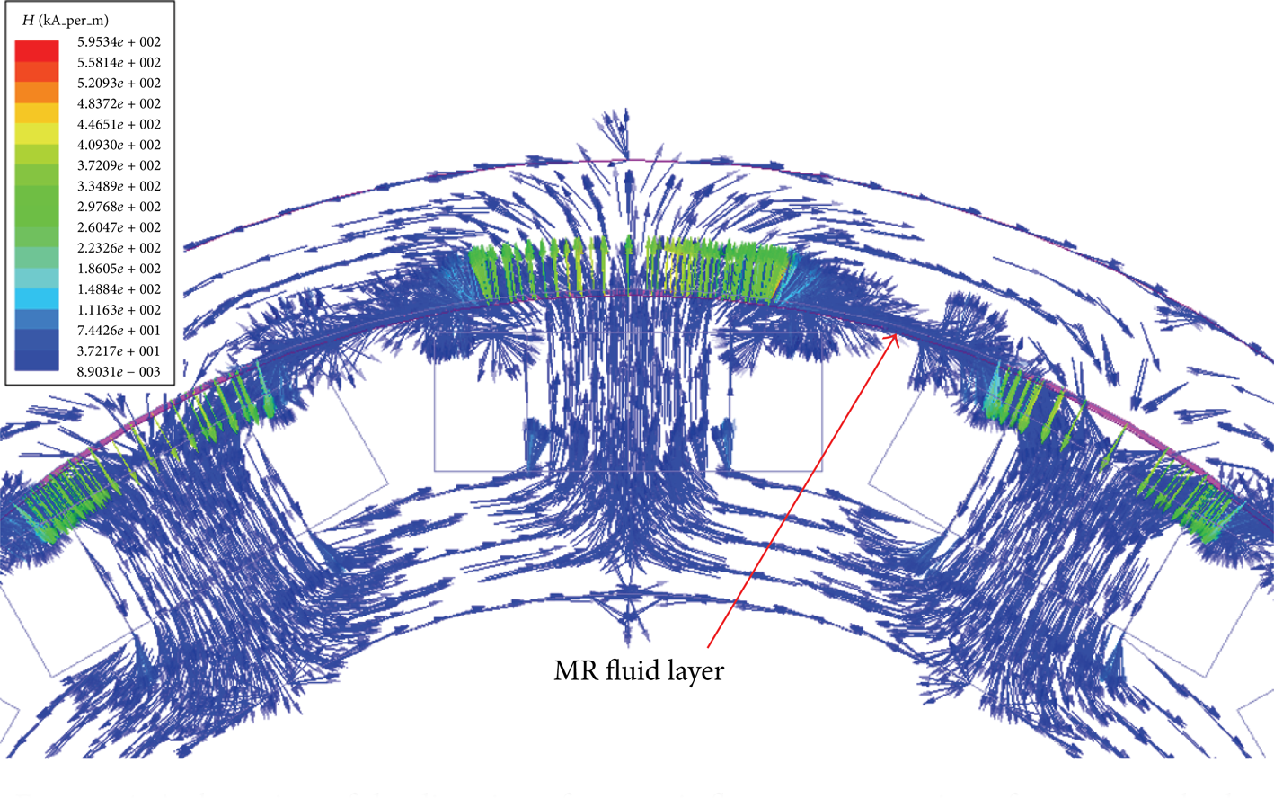
A close view of the direction of magnetic flux on cross section of outer-rotor brake.
Agreeing with the magnetic simulation results above, the simulation results of output torque from those MR brakes are shown in Figure 5. It is noted that these output torques are applicable for motorcycle braking requirement. The outer rotor produces a higher torque of 525 Nm. It is chosen to be used in hybrid ABS for motorcycle brake system.

Simulated torque results of two designs.
2.3. Hybrid ABS System Theorem
There are many kinds of ABS control algorithms available for vehicles. One common way is to maintain vehicle slip ratio in a desired range. Slip ratio, which depends on the contact characteristic between tire and ground as Figure 6, is defined as the ratio of the speed difference between vehicle and tire speeds to vehicle speed:

where r and ω are the radius and angular velocity of tire and vv is motorcycle speed.

Slip ratio for tracking and braking [1].
Motorcycle speed, which is hard to be measured by cheap sensor in practice, is estimated by an accelerometer as [11]

where a meas is measured motorcycle acceleration, v is motorcycle speed, and w(k) is noise signal. If the motorcycle is not slipping, its angular wheel velocity can be expressed as
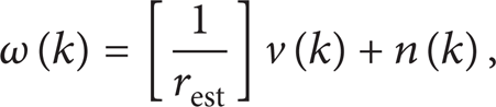
where rest is wheel radius and n(k) is noise. Applying least square method, the motorcycle speed can be approximated as follows:

The value of K2 is determined by the slip ratio as in Figure 7.

The mapping of K2 from slip ratio.
The application of MR brake in ABS for motorcycle has been studied before [12]. However, the development of simulation tool provides better assistance to the design and development procedure. In this study, motorcycle dynamics are simulated in BikeSim which is interconnected with MATLAB/Simulink to execute the controller part. The details of the BikeSim model used in dynamic simulation are shown in Figure 8. The driver model is chosen based on the size and weight of a normal Asia men. A 165 kg scooter is set for simulation on wet and dry roads with friction coefficient μ = 0.5 and 0.85, respectively. The scooter runs at initial speed of 90 km/h and takes brake to decelerate the scooter. The response rate of MR brake is about 0.003's [11]. In Figure 6, it is shown that the road friction coefficient increases near proportionally as the slip ratio increases if the slip ratio is between 0.01 and 0.25. Thus optimal slip ratio is set to 0.2 for the motorcycle ABS control.

Vehicle parameters in BikeSim.
The ABS control strategy has three modes: increasing, maintaining, and decreasing brake torque. The switching slip threshold of MR brake is 0.2, while the switching of hydraulic brake follows the following rules:
slip ratio < 0.17 → increases brake torque;
0.17 < slip ratio < 0.25 → maintains brake torque;
slip ratio > 0.25 → decreases brake torque.
2.4. Ordinary FLC
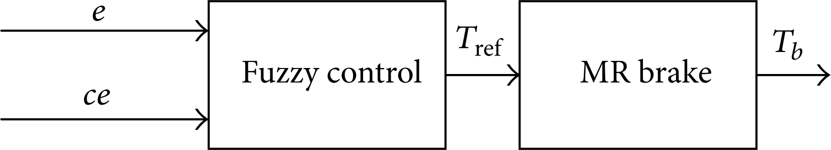
The ordinary fuzzy-logic ABS controller is a two-input single-output controller (see Figure 9). The two inputs are slip error (e) defined by the difference of actual and ideal slip values and the change in slip error (ce) defined as the time deviation of slip error e. A total of 25 fuzzy inference rules were defined as shown in Table 1, wherein NB and NS represent negative errors, ZE represents zero error, PS and PB represent positive errors.
Fuzzy rule base.

Flowchart of ordinary fuzzy controller.
The structure of hybrid ABS with ordinary FLC is shown in Figure 10. As the motorcycle wheel speed and acceleration can be obtained by the software, it will be inputted to speed estimator to obtain the current speed. Based on vehicle speed and wheel speed, the current slip λ can be obtained. After subtracting with ideal slip value, the error value will be inputted to FLC to command the required brake torque Treq, which is used as the demand for the MR brake model to provide dynamic braking reaction by output brake torque Tref. It then returns to BikeSim model for simulation of motorcycle dynamics to maintain the slip ratio around optimal ratio.

Structure of hybrid ABS using ordinary FLC.
2.5. Self-Organizing FLC (SOFLC)
In this study, SOFLC [13] was also considered as alternative controllers for various adaptive problems on the road (as in Figure 11). The difference of this controller to FLC is that although it uses two inputs as variables, the slip error e and the change in slip error ce, the controller uses a look-up table to obtain the calculated control amount (u) or the control correction amount (Δu). The advantage is that it can reduce the computation time and avoid a lot of memory storage by a small rule base.

Flowchart of SOFLC.
For the designed SOFLC, input variables were slip error (e) and the change of slip error (ce). Slip error and change of slip error are within the fuzzy range [−3, 3] with seven intervals. And linear interpolation is used for output defuzzification [14]. The detail structure of hybrid ABS using SOFLC can be seen in Figure 12.

Structure of hybrid ABS using self-organizing FLC.
2.6. The Road Condition Estimator (RCE)
As shown in Figure 13, the road estimator estimates the ideal slip calculated by subtracting the error (e) of torque and inputs to the SOFLC to get Treq. It is then inputted to the MR brake model for dynamic braking reaction of the brake output torque Tref, before returning BikeSim for motorcycle dynamics.

Structure of hybrid ABS with the combination of self-organizing FLC and RCE.
3. Results and Discussions
3.1. Comparison between FLC, SOFLC, and SOFLC Combined with RCE
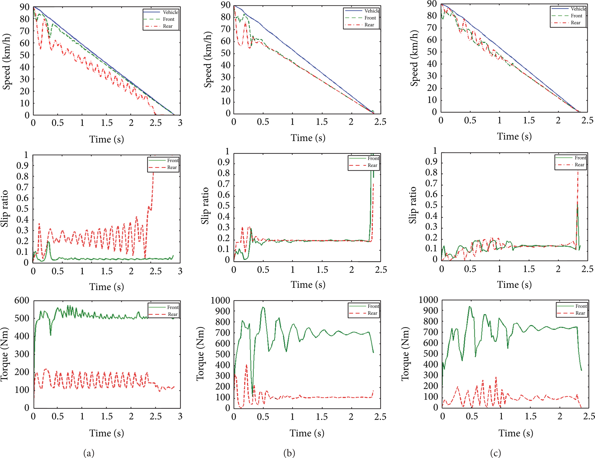
The detailed brake performances of hybrid ABS system using different controllers are seen in Figure 14. The hybrid ABS using SOFLC shows a shorter braking time and distance, which means it has ability to adapt to different roads more efficiently than system using ordinary FLC. Furthermore, the hybrid ABS using RCE also can provide better braking performance than fixed slip differential hybrid ABS, in the case of different road conditions. The brake performance is improved about 12.4% and 3% for wet and dry roads, respectively. In conclusion, the hybrid ABS system with RCE is superior to one with a fixed slip differential.

Responses of the front/rear wheel on wet road surface (a) FLC, (b) SOFLC, and (c) SOFLC with RCE.
From the simulation results shown in Figure 15, ABS with SOFLC provides better control performance under different road conditions. Its slip ratio can be controlled down to the ideal differential slip value (λ = 0.2), which is better than the optimized FLC for wet or dry road. It is because that an ordinary FLC has fixed rule base and membership function which is not adaptive to change of road surface. Parameters of a tuned FLC for dry road are not suitable for wet road condition. Alternatively, the control command from SOFLC is not a fixed value. This control command u can be adjusted immediately to accurately control the desired slip value (λ = 0.2) according to the slip error and change rate of error. Table 2 shows that the SOFLC has shorter stop distance and 17% better brake performance than those of the FLC controller.
The comparisons of stopping time and stop distance of FLC and SOFLC with RCE at different road conditions.

Responses of the front/rear wheel on dry road surface (a) FLC, (b) SOFLC, and (c) SOFLC with RCE.
3.2. Comparison between Conventional Hydraulic ABS and Hybrid ABS
Figure 16 shows the scooter and wheel speeds as well as its torque response for a scooter with pure hydraulic ABS. It shows that the scooter takes about 4.9's to stop the scooter, and the torque reaches about 600 Nm.

Scooter/wheel speeds (a) and brake torque (b) of a pure hydraulic ABS system (μ = 0.5).
If a hybrid ABS system applies a primary hydraulic brake and auxiliary MR brake, the stop time can be reduced to 4.56's (Figure 17), and brake torque has small oscillation. If the hydraulic and MR brakes are examined in Figure 6, respectively, it is obvious that the hydraulic torque is smooth without any high-frequency oscillation. It indicates that only regular hydraulic brake is needed for the hybrid ABS system, not the expensive servo hydraulic one.

Scooter/wheel speeds (a) and brake torque (b) of hybrid ABS system (μ = 0.5).
The torque response of MR brake in Figure 18 shows high-frequency variation. It is because of the fact that MR brake has rapid response rate to provide such a high-frequency torque oscillation. This excellent torque response helps the scooter ABS system to switch very quick to avoid locked brake and shorten brake distance.

Hydraulic (a) and MR (b) torques of a hybrid ABS system (μ = 0.5).
Both of the pure hydraulic ABS and hybrid ABS systems keep the scooter from locked brake and consequent scooter slipping. Since the hybrid brake has MR brake to take charge of high-frequency torque switching, its brake distance is reduced from 69.7 m to 57 m (82%) and stopping time is reduced to 80.7%. However, the pure hydraulic ABS brake only reduced to 85.2% of distance and 86.4% of braking time. It confirms that a scooter equipped by a hybrid brake with auxiliary MR brake can provide excellent brake performance and enhance the driving safety.
4. Conclusions
A hybrid brake system with a primary regular hydraulic brake and an auxiliary MR brake is discussed in this paper. To provide enough torque for scooter brake, two types of MR brake, outer-rotor and inner-rotor, are compared. Simulation results show that an outer-rotor performs better braking torque while it maintains an easy integration to motorcycle wheel. It is then selected as the auxiliary brake system for a hybrid ABS system with a primary regular hydraulic brake. In the hybrid ABS system, the primary hydraulic brake provides the main smooth torque, while the MR brake takes charge of high-frequency switching torque. Two types of controllers, ordinary FLC and SOFLC, are tested. The final selection is the use of SOFLC with RCE. With this optimal brake collocation, the brake distance and stopping time are effectively reduced to 18% and 19.3%. Therefore, brake performance of a scooter with hybrid ABS system is enhanced and driving stability is guaranteed.
Conflict of Interests
The authors declare that there is no conflict of interests regarding the publication of this paper.
Footnotes
Acknowledgment
This study has been sponsored by the National Science Council, Taiwan (NSC project no. NSC 101-2221-E-027-033).