
Abstract
On account of one-target focus type of the heliostats in the tower solar power technology, the heat transfer was analyzed for the vapor-liquid two-phase or single-phase superheated steam in the parallel heated panel bundles of the solar cavity receiver. A nonlinear mathematical model of the hydrodynamic characteristics in the evaporation panels was developed to obtain the flow rate distribution, thermal deviation, and two-phase flow circulation reliability of the working fluid under the severe nonuniform heat flux from the one-target focus of the heliostats. The simulation results show that for the evaporation panels the flow distribution can synchronize with that of the heat flux at the low heat flux, while for the superheater sections the flow distribution decreases with the increase of heat flux. This desynchrony may give rise to stagnation or backflow of the working fluid and lead to the panels burst or erosion due to the local overheating in some extreme situation.
1. Introduction
As we have known, a solar cavity receiver is the essential apparatus to achieve energy conversion in the solar power system. The heliostats field is applied to reflect sunlight into the solar cavity receiver. However, due to the astronomical feature of the sunlight, it is very difficult for heliostats to track the sun path in real time because of the clunky and complicated controlling system. Generally, a prevailing concentration technique of one-target focus type of the sunlight is feasible, in which a sole predetermined target is stationary relative to the heliostat and the light is reflected in a fixed direction. The heat flux distribution of the beam spot focused on the inside surface of the receiver, from the one-target focus type, varies widely in time and space, that is, the inherent characteristics of the sunlight central concentration. Comparing with the traditional fossil fuel boiler, the nonuniform coefficient, the ratio of heat flux in the center of the light spot to one around its edges, is approximately 18 times that of the boiler [1, 2]. Regarding the above-mentioned circumstance of nonuniform heat flux, a severe consequence for influencing the hydrodynamic characteristics in the heated panel occurs, such as stagnation or backflow of the working fluid. Furthermore, the regular measure for the installation of throttle orifice in the parallel tube bundle is not applicable to adjust the flow distribution appropriately. Consequently, the flow rate is not consistent with the heat flux; that is to say, the low flow corresponds to the high heat flux. This situation causes the excessive heat on the certain receiver surfaces and the deterioration for the flow rate distribution and the water cycling reliability, which may makes the panels burst or ablative and gives rise to stagnation or backflow and ever affects the stability of the whole system in extreme conditions. Thus, the study on hydrodynamic characteristics of solar cavity receiver under highly focused heat flux is very essential.
So far, there has been much attention paid to the heat flux distribution into the cavity receiver and the accurate ray tracing technique for the heliostat field [3]. The Monte Carlo ray tracing method (MCRTM) was based on the probability theory, which was used to design and evaluate the thermal performance of the cavity receiver in the first MW-class pilot solar tower power station in China [4, 5]. The results are fully similar with the test data of CESA-Ι, which is one of the pioneering solar power tower plants all over the world and built in Spain in 1982. The heliostats field calculation (HFCAL) analysis model is provided by Schwarzbolz and cooperators [6], who proposed a novel calculation method of heat flux under single-point focused heliostat mirrors. Collado [7] revealed that the heat flux distribution obtained by HFCAL can be verified by available experimental data.
Nowadays, the studies on the hydrodynamic characteristics of solar cavity receiver are very few. Most of these studies were focused on the hydrodynamic characteristics being caused by the stability of the temporal changing heat flux, while little literature on the special changing effect of the nonuniform heat flux on the hydrodynamic characteristics and the water cycling reliability is delivered [8–10]. Also, the objectives of available studies on the hydrodynamic characteristics were aimed at mostly the conventional boilers. However, it is certain that although there are some differences between the solar cavity receiver and the conventional boiler, these methods in the hydrodynamic characteristics against the boilers are true to the solar cavity receiver.
In this paper, according to the layout and workflow in the heat panels of solar cavity receiver, combined with HFCAL analysis calculation model and the energy transfer in the process of radiation-heat-convection, the heat transfer was analyzed in the vapor-liquid two-phase or single-phase superheated steam. Based on the heat transfer calculation, a nonlinear mathematical model of the hydrodynamic characteristics under the nonuniform heat flux was developed. Finally, the flow rate distribution, thermal deviation, and steam-water circulation reliability of working fluid under the heat flux will be obtained, which can provide references for the design and control of solar power tower system.
2. The Steam-Water System of the Cavity Receiver
The prototype of the cavity receiver in this study is from the 1MW pilot solar power station located in Yanqing County, Beijing, China. As shown in Figure 1, the cavity receiver is a hexagonal prism shape with an aperture at one side, by which the focused incident radiation from the heliostats field enters the inner of the receiver and is absorbed by the heated panels attached at the inner walls of the receivers. In Figure 2, the heated panels consist of the evaporation panels and superheater sections. The evaporation panels have three panels with vertical pipe bundles that were welded together to form a membrane wall, two of which are arranged at the two lateral sides of the cavity and the third is at the wall opposite to the aperture. The superheater sections are arranged at the two lateral sides, parallel laid before the evaporation panels. In order to achieve steam-water separation and stabilize the steam-water system, a steam drum and a circulation pump are designed in the system while a set of attemperators is installed to allow control of the superheated steam temperature. The upper and lower bottoms and the outer panels of the receiver are coated with insulation material, which can prevent the loss of heat from high temperature walls.

The prototype of 1MW tower solar cavity receiver.

The A-A view cross section shown in Figure 1 for the cavity receiver.
3. Mathematical-Physical Model
3.1. Heat Transfer Performance
The parallel pipe is shown in Figure 3. To simplify, three hypotheses are as follows: (a) the heat flux distribution on each heated panel is uniform along the axial direction; (b) a half of the heat panel is heated along the circumferential direction; (c) the thermal insulation materials are used in the shady side at the heated panel.

Parallel tube circuit schematic diagram.
The energy conservation equation of the panel is as follows:

According to the Newton cooling formula, the forced convection of panels can be calculated [2]:

The convective heat transfer coefficient α0 of working fluid is obtained by the turbulent heat transfer formula. For the cold-water or superheated single-phase steam under the critical pressure, the following formula can be used [11]:

For the vapor-liquid two-phase flow, the convective heat transfer coefficient can be computed by the saturated boiling formulas [12]:
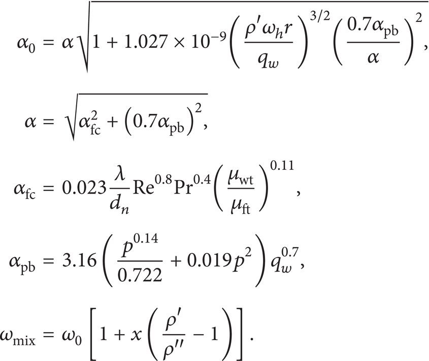
The convection heat loss is obtained by the large space natural convection heat transfer formulas [2]:

The radiation heat loss at the single panel can be computed as follows:

The working fluid of water with a certain supercooling degree enters into the evaporation panels and absorbs the heat from the heliostat field. The distances for absorption from the start heating spot to the start boiling spot are called as the supercooling length, which is mainly affected by some factors, such as working medium inlet enthalpy, panel medium velocity, and heat flux quality.
For the evaporation system in which the average circulation ratio, the flow rate of working fluid in the evaporation panels divided by evaporation capacity, is K, the supercooling length can be obtained by the iterative algorithm according to the following formulas:

where i′ is the enthalpy of saturated water under the drum pressure, kJ·kg−1; Qabs′ is the absorbed heat from supercooling state to saturated state, W; Qtot′, Qrad′, and Qcon′ are the panel total radiation energy, the loss of radiant heat, and convective heat in the supercooling section, respectively, W.
3.2. Flow Characteristics
For the parallel tube bundle in the evaporation panels, each tube works under the pressure difference which is formed by the up and bottom boiler header. Due to header effect, the in-and-out pressure difference of each tube varies slightly. For the subcooling water or mixture of lower quality steam and single-phase water, the header effect can be ignored. However, for the single-phase superheated steam, the header effect should be considered because of the increase of the flow resistance while the acceleration pressure drop of working fluid can be ignored [13].
For the subcooling water or mixture of lower quality steam and single-phase water, the pressure drop between adjacent panels is as follows:


The following equation can be deduced by (8a), (8b), and (8c):
For the single-phase superheated steam in the superheater sections, the pressure drop between adjacent tubes is obtained:

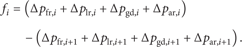
Taking mass conservation equation into account, n nonlinear equation set of the tube can be got:

Normally for every pressure difference Δp i , it includes three parts: frictional pressure drop, acceleration pressure drop, and gravity pressure drop and header resistance. Regarding frictional pressure drop, it consists of frictional resistance and local resistance. For single-phase flow, the frictional resistance is computed by the following equations:

For steam-water two-phase flow, the homogeneous flow model is adopted for using frictional coefficient correlation as follows:

The local resistance for single-phase fluid is obtained as

For the steam-water two-phase fluid,

Under the certain critical pressure, the acceleration pressure drop can be neglected. In the area where the heat flux and specific heat are both larger, the homogeneous model is used in the calculation of acceleration pressure drop of steam-water two-phase flow as follows:

For single-phase fluid, the gravity drop is depicted as

For steam-water two-phase flow, the following is used:

The header resistance is used to consider the effect of the header on the flow characteristics, while the pressure difference Δpf,i and the pressure difference Δph,i can be obtained as follows:


where Δpf,i is the pressure difference between the inlet of i panel and the inlet of distributive header, Pa, Δph,i is the pressure difference between the outlet of i panel and the outlet of collective header, Pa, and Δp fL and Δp hL are the total hydrostatic pressure difference of distributive and collective header, Pa.
3.3. Flow Reliability
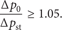
The steam-water circulation reliability means that all the panels can be cooled normally and sufficiently by the flow. When the flow rate is lower at the higher heat flux panel, and the stagnation or backflow happens, the steam-water circulation reliability will be affected. Thus, the stagnation or backflow should be studied inevitably.
In the single-phase water system, the ratio of Δp0 to Δp tz must be larger than 1.05 to avoid the stagnation:
The stagnant pressure drop of riser panels can be got by

The backflow does not happen, when

where
4. Results and Discussion
As mentioned above, in the solar power plant the sunlight is focused at certain point of the cavity receiver by the heliostats, called one-target focus type. For this focus type, the flux distribution is more nonuniform; that is to say, the heat flux is extremely distinguished in the different panels. This makes the flow rate distribution and thermal deviation irrational, leads to overheating or ablation of the panels, and even stabilizes the flow assurance of the receiver.
In the present case, in order to illustrate the local nonuniformity of focused light spot, the correlation of the heat flux distribution under the one-target focus can be employed [6]:
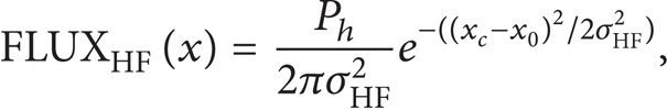
where x0 is the spot center's coordinates, m, xc is the corresponding coordinates of heat panels width, m, and σHF2 is the effective deviation coefficient of thermal radiation in the heliostat field.
As shown in Figure 4, with the increase of the effective deviation coefficient, the heat flux curve becomes smooth gradually, and vice versa, which means that heat flux distribution gets more and more uniform. Also, it is assumed that the pressure of the steam-water system in the receiver is up to 5 MPa. The following gives the results of the flow rate distribution, thermal deviation, and the steam-water circulation reliability of working fluid under the average incident radiation flux of 100 kW/m2 or 400 kW/m2 for the focused light spot on the heated panel in the receiver.

Heat flux distribution in the different effective deviation coefficient.
4.1. Flow Rate Distribution
The varieties of the flow rate distribution in the evaporation panels and the superheater sections are shown in Figures 5 and 6.

The heat flux and mass flow of evaporation panels.

The heat flux and mass flow of superheater section.
The heat flux and mass flow of evaporation panels are shown in Figures 5(a) and 5(c). It is shown from Figure 5(a) that the changes of the heat flux are consistent with that of mass flow, and the mass flow is large while the heat flux is high. However, when the heat flux achieves a certain value, the mass flow will begin to decrease along with the increase of heat flux (as shown in Figure 5(b)). When the extent of vaporization is lower at the beginning, the gravitational pressure drop is dominant in the total pressure drops of evaporation panel. And then, with the increase of heat flux, the gravitational pressure drop decreases accompanied with the raise of flow resistance. But mass flow will increase, provided that the rate of the gravitational pressure drop reduced is larger than that of flow resistance increased. If the heat flux goes on raising, flow resistance will play a lead role in the total pressure drops and the mass flow will reduce, and then the synchronization phenomenon vanishes [14, 15]. In Figure 5(c), the nonuniform coefficient of flow can be obtained under the condition of 100 kW/m2 and 400 kW/m2. The steam-water system has a well synchronization at 100 kW/m2; when the heat flux is at 400 kW/m2, the synchronization occurs in the outside regions which are far away from the focusing spot center and vanishes in the focusing spot center regions. With the intensification of the heat flux, the distribution of flow rate does not synchronize with that of heat flux gradually. The ablation may appear in the panel under this condition, which can threaten the power system greatly.
It is noted from Figure 6 that the variations of mass flow in the superheater sections are different from those in the evaporation panels. In the superheated panels, the density of the superheated steam is lighter, and the specific heat capacity is greater. When the heat flux strengthens, the flow resistance is elevated and the mass flow is reduced. Thus, with the increase of the heat flux and reduction of the flow, the panels are at the extremely high temperature and cannot be cooled timely around the focusing spot center, which will cause significant ablation.
4.2. Thermal Deviation
Due to the differences of heat flux and mass flow among adjacent panels, the thermal deviation will occur inevitably. By calculating the incremental enthalpy, the thermal deviation of working fluid in the evaporation panels and superheater sections is illustrated as shown in Figure 7.

The thermal deviation of working fluid in the evaporation panels.
From Figures 7(a) to 7(d), the thermal deviation of working fluid in the evaporation panels can be obtained. In Figure 7(a), the incremental enthalpy can be worked out with the system pressure for 5 MPa and radiation flux for 100 kW/m2. The variations of incremental enthalpy are consistent with those of heat flux around the focusing spot center. When the heat flux decreases to a certain value, however, the incremental enthalpy begins to increase in the area far away from the focusing spot center. The same results conclude from Figure 7(b), and the incremental enthalpy increases with heat flux after the first cut increases. That is because the mass flow and heat flux are the two factors of the incremental enthalpy. When the heat flux reduces to a certain range, the heat absorption per unit mass is larger, and the incremental enthalpy also increases, despite the lower heat flux.
The incremental enthalpy distribution in the evaporation panels corresponding to the heat flux for 100 kW/m2 and 400 kW/m2 is shown in Figure 7(c). In the figure, when the average heat flux is 100 kW/m2, the incremental enthalpy is well-distributed; while the flux is 400 kW/m2, the distribution is relatively uniform in the circumjacent area that is far away from the focusing spot center, and the incremental enthalpy and the thermal deviation become larger in the spot center because of the disappearance of the synchronization. The larger deviation will lead to overheating of panels.
With the increase of the incremental enthalpy, the extent of vaporization also rises. In Figure 7(d), the outlet steam quality of the working fluid is shown. When the heat flux is low, the bubbles attaching to the panel wall cannot be taken away as a result of the lower mass flow. The regions where the bubbles gather are overheating, and then the bubbles break, and those regions are full of water for cooling again. Such process continually happens over and over again with a high frequency. Ultimately, a consequent thermal fatigue will be extremely likely on the panels.
As shown in Figures 8(a) and 8(b), the distributions of the incremental enthalpy and wall temperature in the superheater sections can be obtained. It is suggested that the incremental enthalpy increases with the enhancement of the heat flux in Figure 8(a). As mentioned above, the higher heat flux and the lower mass flow will lead to higher incremental enthalpy and larger thermal deviation. The working fluid on the superheater is single phase. Therefore, the temperature of working fluid and wall goes up as the incremental enthalpy increases. We can see from Figure 8(b) that the wall temperature is higher in the focusing spot center and lower on both sides of the circumjacent area. For this reason, the higher wall temperature makes the superheater sections overheated or ablative.
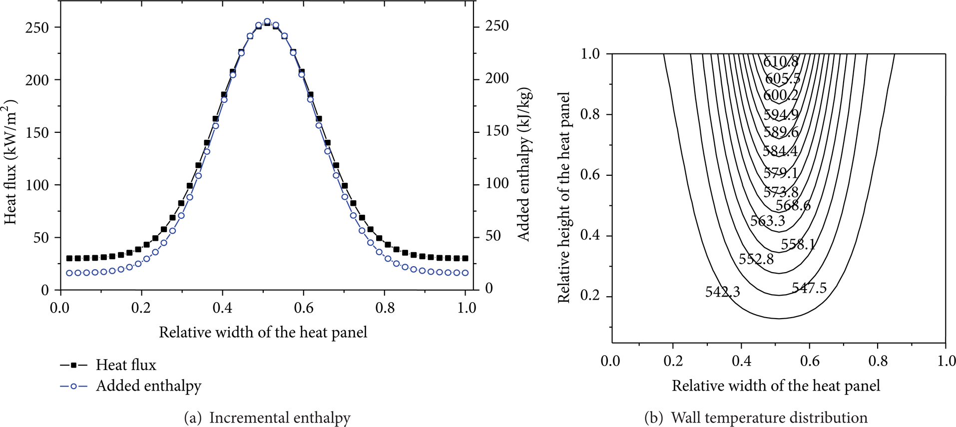
Thermal deviation characteristics in the superheater sections.
4.3. Flow Reliability
When the natural circulation or forced circulation used in the steam-water system is pressurized insufficiently, the mass flow is also lower in the panels where the heat flux is smaller. Once the circumstance occurs, it causes stagnation or even backflow.
In Figure 9, it is suggested that the working fluid may stagnate in the regions far from the focusing spot. The profile of the steam-water circulation reliability illustrates that the backflow occurs in the panels where heat flux is weak firstly. The complete pressure drop curve of the panels is shown in Figure 10, which suggests that the maximum pressure drop goes lower with the increase of the heat flux. The maximum pressure drop of the panels of which heat flux is lower is larger. In other words, the fluid of the lower heat flux panel easily flows back. It is seen from Figure 11 that the maximum pressure drop happens in the inlet and outlet, so the fluids of the inlet and outlet are liable to backflow probably.
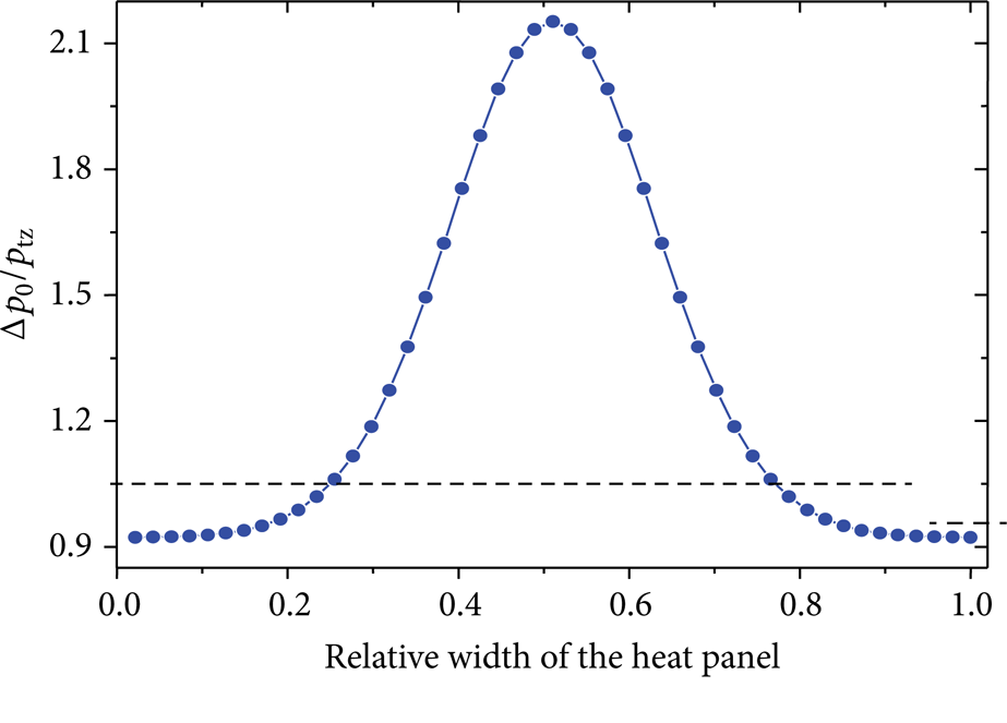
The ratio of inlet/outlet and stagnation pressure drop.

The complete pressure drop with different pressure drop.

Maximum pressure drop of backflow.
5. Conclusions
Under the single-spot focused incident radiation, an online hydrodynamic mathematical model in steam-water two-phase flow in the solar cavity receiver is proposed. The flow rate distribution, thermal deviation, and the steam-water circulation reliability of working fluid in the evaporation panels and superheater sections of the receiver are analyzed in detail. The results are shown as follows.
(a) For the evaporation panels, the flow rate can be synchronized with the heat flux when the steam quality is low. However, as the heat flux increased, the synchronization disappears due to the excessive local heat flux, resulting in the deterioration of flow rate distribution and thermal deviation.
The variations of incremental enthalpy are consistent with those of heat flux around the focusing spot center; when the heat flux decreases to a certain value, the incremental enthalpy begins to increase in the area which is far away from the focusing spot center.
The working fluid may stagnate and flow back in the areas that are far from the focusing spot. When the stagnation happens, thermal fatigue will occur in the panels.
(b) For the superheater sections, the flow rate decreases with the increase of the heat flux, which leads to overheating and ablation of the panels due to overheating.
The incremental enthalpy increases with the enhancement of the heat flux; the wall temperature is higher in the focusing spot center and lower on both sides of the circumjacent area. For this reason, the higher wall temperature makes the superheater sections overheated or ablative.
(c) Considering the feature of the one-target focus type, the hydrodynamic mathematical model under the multipoint focus can be built to study the characteristics of the heat panels next.
Footnotes
Nomenclature
Conflict of Interests
The authors declare that there is no conflict of interests regarding the publication of this paper.
Acknowledgments
This work has been financed by the National Natural Science Fund of China (no. 51276144) and the Major State Basic Research Development Program of China (973 Program) (no. 2010CB227102).