
Abstract
Portal frame structures are widely used in industrial building design but unfortunately are often damaged during an earthquake. As a result, a study on the seismic response of this type of structure is important to both human safety and future building designs. Traditionally, finite element methods such as the ANSYS and MIDAS have been used as the primary methods of computing the response of such a structure during an earthquake; however, these methods yield low calculation efficiencies. In this paper, the mechanical model of a single-story portal frame structure with two spans is constructed based on the transfer matrix method of multibody system (MS-TMM); both the transfer matrix of the components in the model and the total transfer matrix equation of the structure are derived, and the corresponding MATLAB program is compiled to determine the natural period and seismic response of the structure. The results show that the results based on the MS-TMM are similar to those obtained by ANSYS, but the calculation time of the MS-TMM method is only 1/20 of that of the ANSYS method. Additionally, it is shown that the MS-TMM method greatly increases the calculation efficiency while maintaining accuracy.
1. Introduction
Because portal frame structures have many advantages, which include good aesthetics, low cost, and rapid construction [1], this type of structure is widely used in small and medium-sized industrial buildings, warehouses, and large supermarkets [2]. Additionally, China is a country in which earthquakes frequently occur, according to readily available earthquake disaster data [3]. Although steel structures have some advantages, they are still regularly damaged during an earthquake, requiring special attention and study, particularly with regard to portal frame structures [4].
With the increasing demand for a calculation method for the seismic response of a building, low calculation efficiency has become a serious hindrance to many methods, preventing them from being widely applied in the field of civil engineering [5]. Therefore, searching for a simple, fast, and accurate earthquake response analysis method is an important area of research that engineers and scholars have been working towards for many years [6]. Currently, the dynamic response with a time history for a portal frame structure under the action of an earthquake is generally calculated by a finite element software [7, 8], such as ANSYS [9] or MIDAS; unfortunately, for the complex civil structure with a large number of degrees of freedom, the computational work load is heavy, which cause long calculation times and low calculation efficiencies.
The transfer matrix method of multibody system (MS-TMM) [10] was developed by Xiaoting Rui in 1993 and was mainly divided into the transfer matrix method of linear multibody system [11] and discrete time transfer matrix method [12]. The former method mainly determined the vibration characteristics of a linear multibody system [13], while the latter mainly solved the time-varying, nonlinear, large motion, controlled, or another general multibody system dynamic problem [14]. Compared to the classical transfer matrix method, MS-TMM has the following advantages: (1) no global dynamics equations of the system are required; (2) only high-level programming is required; (3) a low order of system matrix usually results; (4) high computational efficiency is existed [15]; and (5) the “morbidity” problems inherent to eigenvalue calculations are avoided [16]. At present, the transfer matrix method of multibody system has already been applied in the field of civil engineering [17]. Additionally, the transfer matrix of some typical elements of civil engineering structures has been established.
In this paper, the MS-TMM method is used to calculate and analyze the vibration characteristics and seismic response of a portal frame structure, which are then compared to the results obtained by the traditional ANSYS method. The calculation efficiencies of these two methods are also compared.
2. Mechanical Model of Portal Frame Structure
The general idea of the transfer matrix method of a multibody system is first to divide the complex multibody system into several components by using discrete thought. The components are considered to contain two types: a “body” and a “hinge.” The “body” mainly includes the rigid body, the flexible body and a concentrated mass. The “hinge” is the connection between one “body” and the next “body”; it is massless because the mass of hinge is included in the adjacent “body.” Next, a matrix is used to express the mechanical properties of each element. Finally, “assembly” of the transfer matrix of each element is combined to obtain the total transfer equation and the total transfer matrix of the system.
In this paper, a portal frame structure is considered as a multibody system. According to the features of the multibody system for a portal frame structure, beams and columns are divided into particles (i.e., the “bodies”) and massless beams (i.e., the “hinges”); massless beams are used to link particles together; the axial deformations of the beams are ignored. Because each portal frame in the longitudinal direction is nearly symmetrical, the original spatial system can be simplified into a planar system. Now, a representative planar portal frame model of the structure is selected to study its response during an earthquake; this mechanical model is shown in Figure 1. The elements of the columns and the inclined beams include the massless beams and particles. The massless beams of the left, middle, and right columns are labeled as 1, 3, …, j–1; 1′, 3′,…, j′ – 1; and 1″, 3″,…, j″ – 1, respectively, and the particles are labeled as 2, 4,…, j–2,j; 2′, 4′,…, j′-2,j′; and 2″, 4″,…, j″-2,j″, respectively. The massless beams of the left and right inclined beams are labeled as l1,l3,…, li and r1,r3,…, ri, and the particles are labeled as l2,l4,…, li–1 and r2,r4,…, ri–1.

Mechanical model of the multibody system for a portal frame structure.
3. Calculation Principles of the MS-TMM
3.1. Transfer Path and Method of the Multibody System for a Portal Frame Structure Based on Its Characteristics
Because the mechanical model of the multibody system for a portal frame structure is a bifurcated system, and the number of elements is large, the transfer equation will thus be very complex when using the traditional transfer matrix method of multibody system. Therefore, in this paper, the physical links between the beams and columns are assumed to be disconnected, and the corresponding relations at the nodes including j, j′, and j″ are replaced by state vectors based on the deformation compatibility relation of the inclined beams. As shown in Figure 2, the main research objects are the three steel columns, each of which is a chain system, and the state vector of each point is transferred in the direction shown by the arrow.

Calculation principles of the transfer matrix of the multibody system for a portal frame structure.
The left column has one input (
The mechanical model of the portal frame structure involves only two elements: a massless beam and particle. The transfer matrix method of a linear multibody system is used to solve the natural period of the structure, and the discrete time transfer matrix method is used to analyze the seismic response of the structure to both common and rare earthquakes.
3.2. Analysis of the Natural Period of the Structure Based on the Transfer Matrix Method of Linear Multibody System
The transfer matrix method of linear multibody system is used to determine the natural period of the structure; the mechanical model of the portal frame structure used is shown in Figure 1. The state vector under physical coordinates of the element in plane motion is defined as

for the middle column:

for the right column:

To unify the coordinate systems,

The three steel columns of the portal frame structure can be viewed as three chain systems; the resulting transfer equations are as follows:

where

The element j′ has two inputs (

where

The output state vector is

According to the deformation compatibility relation of the left and right inclined beams, respectively, the following is derived:

For this model,

Therefore,

Because the element j′ is a particle, all displacements are equivalent and the following is true:
where

This yields

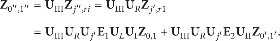
Combining equations (14) and (17) yields

where

The relationship between the state vectors under the physical and modal coordinates is z =

The transfer matrix of a particle is expressed as follows:

with the following boundary conditions:

Zero elements can be removed from
3.3. Analysis of the Seismic Response of the Structure Based on the Discrete Time Transfer Matrix Method
The discrete time transfer matrix method of a multibody system is used to determine seismic response of the structure during common and rare earthquakes; an elastic-plastic restoring force model is also established to analyze the response to a rare earthquake. Numerical solutions are typically used because analytic solutions are usually not available when the change in external load is complex. Generally, during the physical process at each time step, the relationship between the physical variables can be approximately regarded as linear as long as the time step is small. In this paper, the equations are linearized on the basis of the Newmark-β method, which provides an efficient solution.
3.3.1. Extended Transfer Matrix of a Massless Beam and a Particle in a Portal Frame Structure
An external force f should be considered in the transfer matrices of elements. The state vector of the element in plane motion is thus defined as
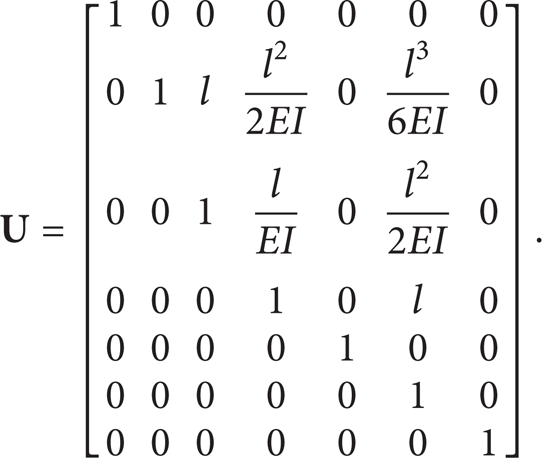
The extended transfer matrix of the massless beam is as follows:
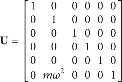
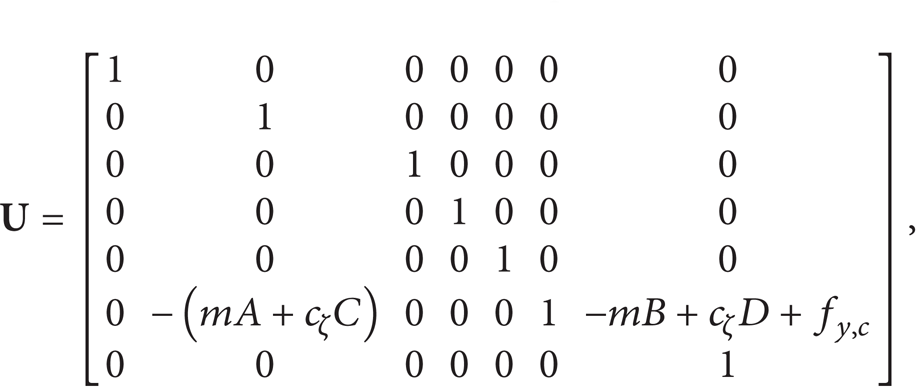
The extended transfer matrix of the particle is as follows:

where m is the mass of the particle; cζ is the damping of the structure;
3.3.2. Calculation Process of Solving the Response of the Structure
The calculation process is shown as Figure 3; MATLAB programming software was used to calculate the solutions shown.
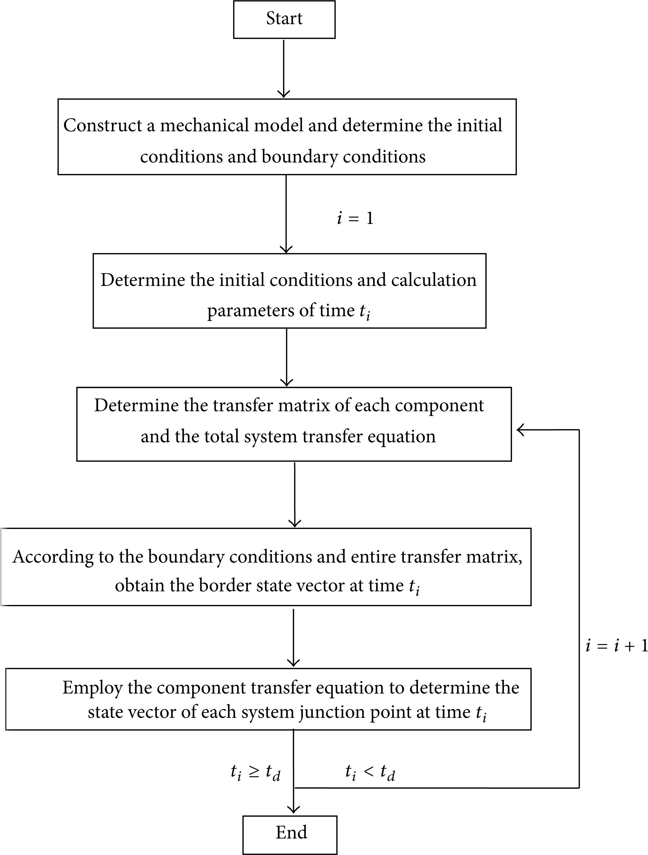
The process of solving the seismic response of a structure using MS-TMM.
4. Engineering Example
In this section, a single-story double-span portal frame structure is used as an example. The span is 18 m × 2; the wall and roof panel are both made of colored profiled sheets whose theoretical areal masses are 6.5 kg/m2. The grade of the loads is I, and the snow load is 0.35 kg/m2. For a steel structure, E = 2.06 × 10¹¹ N/m2.
The seismic fortification intensity is set to 7, the site type is II, and the designed earthquake is designated as a 1st classification. According to the Code for Seismic Design of Buildings of China, when the response of the structure is studied under common and rare earthquakes, the peak value of the acceleration versus time data is adjusted to 35 cm/s2 and 220 cm/s2, respectively. In this study, a natural earthquake wave (i.e., the El Centro earthquake wave) is chosen for the analysis of the seismic response of the structure. Due to the earthquake duration time, which is required to be from 5 to 10 times the structure's natural period, according to the Code for Seismic Design of Buildings of China, the earthquake duration time is set to 10's in this study.
The calculation model of the portal frame structure is shown as Figure 4, and the calculation parameters are shown as follows:


The calculation model of the portal frame structure.
To analyze the seismic response of the portal frame structure obtained by the transfer matrix method of a multibody system, the finite element software ANSYS was used to model the system to produce results for comparison with the new proposed method. When modeling, beams and columns were established by Beam188 elements, the I-type and circular tube sections were defined, the left and right columns and the inclined beams were both set as tapered members, and the sections were set as I-type sections. The beam-column joint sections were enlarged, the middle column section was set as a circular tube, and the column foot was fixed.
4.1. Vibration Characteristics of the Portal Frame Structure
The first five orders of the natural period of the portal frame structure obtained by MS-TMM and ANSYS are listed in Table 1, and the errors between these two methods are also listed.
Natural period T (s) of the structure obtained by the two methods.

As listed in Table 1, the natural periods obtained by these two methods were similar, yielding a maximum error of 14.87%; this is within the limits of engineering precision. The calculation time of the MS-TMM method was approximately 1/7 that of the ANSYS method; therefore, MS-TMM greatly improved the calculation efficiency of this problem.
4.2. Analysis of the Seismic Response of the Portal Frame Structure during a Common Earthquake
4.2.1. Analysis of the Displacement for the Top of the Column of the Portal Frame Structure
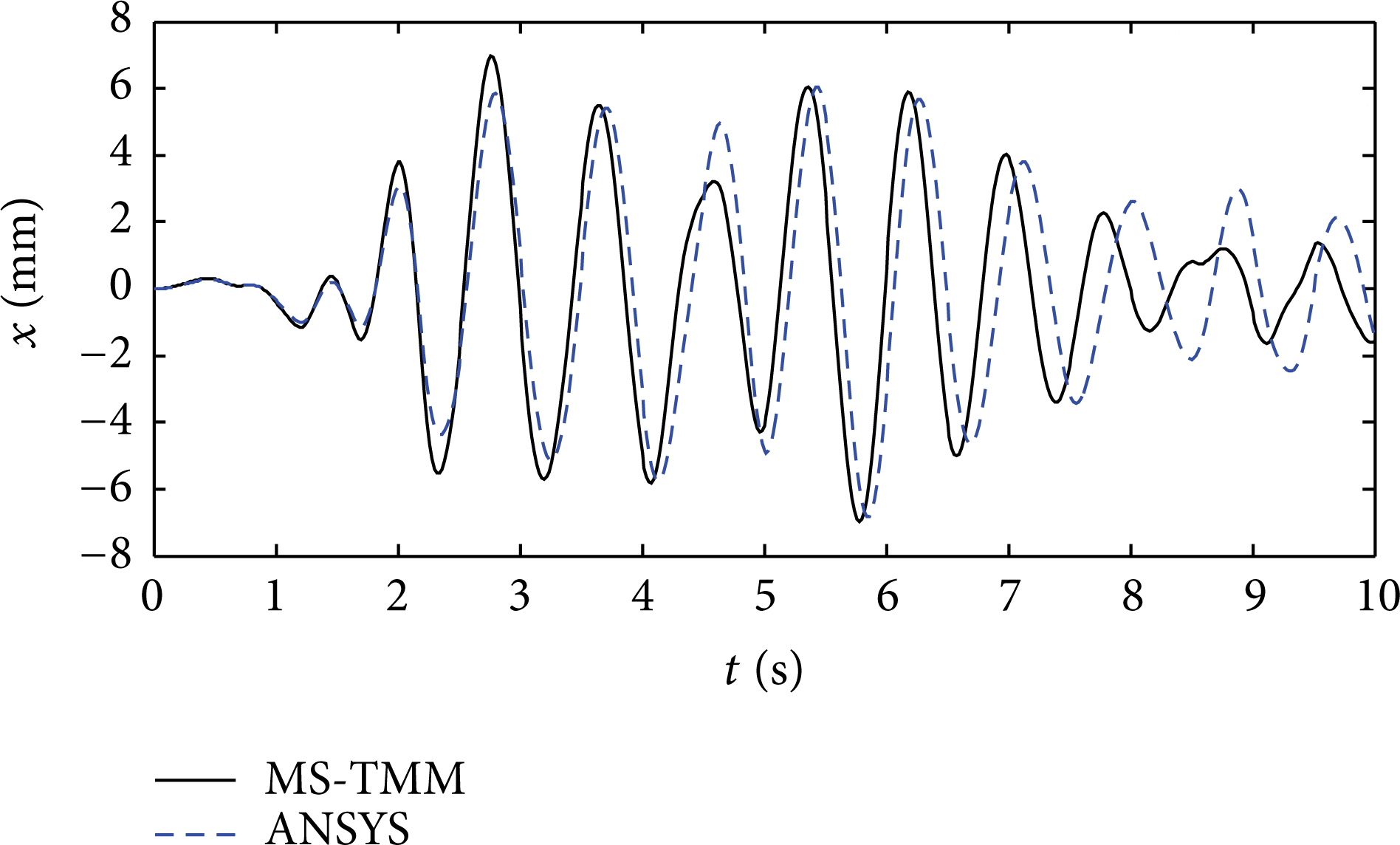
The displacements for the tops of columns A and B during a common earthquake based on MS-TMM and ANSYS are shown in Figures 5 and 6, respectively.

The displacement time history curves for the top of column A during a common earthquake.
The displacement time history curves for the top of column B during a common earthquake.
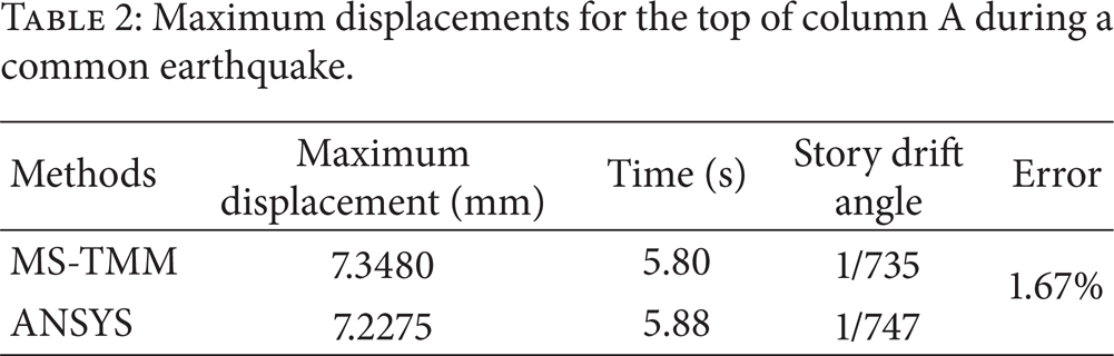
The maximum displacements and elastic story drift angles for the tops of columns A and B during a common earthquake obtained by MS-TMM and ANSYS are listed in Tables 2 and 3, respectively, and the error between these two methods is also listed.
Maximum displacements for the top of column A during a common earthquake.
Maximum displacements for the top of column B during a common earthquake.

As listed in Tables 2 and 3, the trends of the displacement time history curves obtained by MS-TMM and ANSYS are similar. The maximum elastic story drift angle also did not exceed 1/250; this indicates that the portal frame structure satisfies the requirement of the Code for Seismic Design of Buildings of China. The maximum displacements for the top of columns obtained by these two methods are similar and show a maximum error of 2.31%, which is in agreement with typical engineering precision. The calculation time based on MS-TMM was approximately 1/15 that of the ANSYS method, reflecting the high calculation efficiency of MS-TMM.
In addition, the shapes of the displacement history curves for the tops of columns A and B are similar and almost reach their respective maximums at the same time; the latter value is slightly smaller than the former, and their ratio is approximately 0.95, which indicates that the deformation of beam is primarily an integral translation caused by the horizontal seismic force.
4.2.2. Analysis of the Shear Force on the Bottom of the Column of the Portal Frame Structure
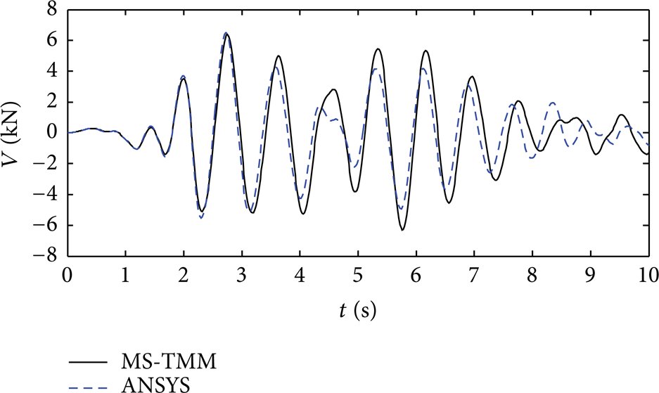
The shear forces on the bottom of columns A and B during a common earthquake based on MS-TMM and ANSYS are shown in Figures 7 and 8, respectively.
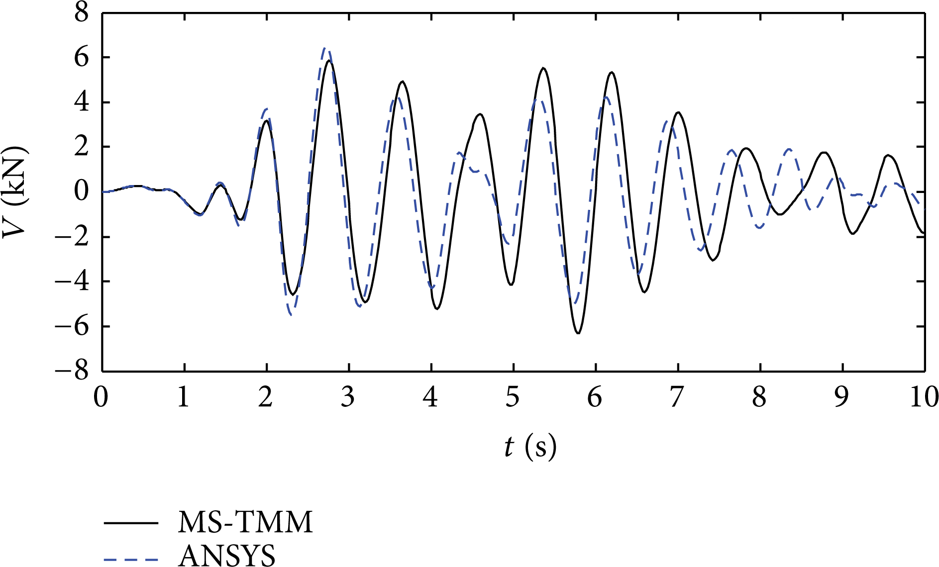
The shear force time history curves for the bottom of column A during a common earthquake.
The shear force time history curves for the bottom of column B during a common earthquake.
The maximum shear forces on the bottom of column A and B during a common earthquake obtained by MS-TMM and ANSYS are listed in Tables 4 and 5, respectively, and the error between these two methods is also listed.
Maximum shear forces on the bottom of column A during a common earthquake.

Maximum shear forces on the bottom of column B during a common earthquake.

As listed in Tables 4 and 5, the trends of the shear force time history curves obtained by MS-TMM and ANSYS are similar, their maximum values are similar, and the maximum error is a low 2.87%. The calculation time of the MS-TMM method was approximately 1/15 that of the ANSYS method, showing a significant improvement in calculation efficiency. However, the shear force on the bottom of column B is shown to be slightly larger than that of column A.
4.3. Analysis of the Seismic Response of the Portal Frame Structure during a Rare Earthquake
4.3.1. Elastic-Plastic Restoring Force Model of the Structure
Because the structure exhibits elastic-plasticity during rare earthquakes, the stiffness varies with time; thus, it is important to establish the relations between the restoring force and the displacement. According to the commonly used restoring force models, the model of the bilinear restoring force is selected for this paper.
As shown in Figure 9, two broken lines are used for this bilinear restoring force instead of positive and reverse skeleton curves; the fold point is used as the yielding point, and the stiffness is not degraded but rather kept at the initial stiffness k1 during the unloading process.

Bilinear restoring force model.
The bilinear restoring force model has the following features.
Two broken lines are used to represent the positive and reverse skeleton curves;
the unloading stiffness is equal to the elastic stiffness k1 and does not degrade;
the positive and reverse skeleton broken lines are antisymmetric.
The bilinear model curve can be determined according to the following parameters:
the elastic stiffness k1,
the yielding load F y ,
the stiffness k2 after yielding.
For the steel structure in this paper, k1 = 200 GPa, F y = 235 MPa, and k2 = 6100 MPa.
4.3.2. Analysis of the Displacement of the Top of the Column of the Portal Frame Structure
The displacements for the tops of columns A and B during a rare earthquake based on MS-TMM and ANSYS are shown in Figures 10 and 11, respectively.
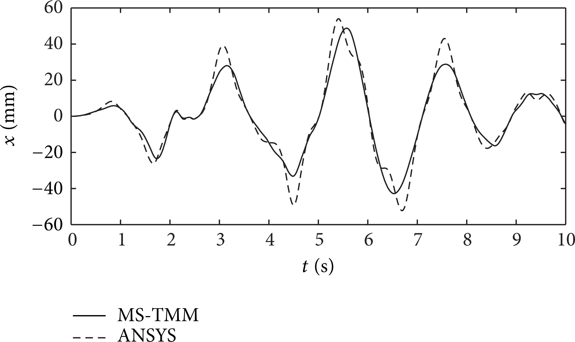
Displacement time history curves for the top of column A during a rare earthquake.
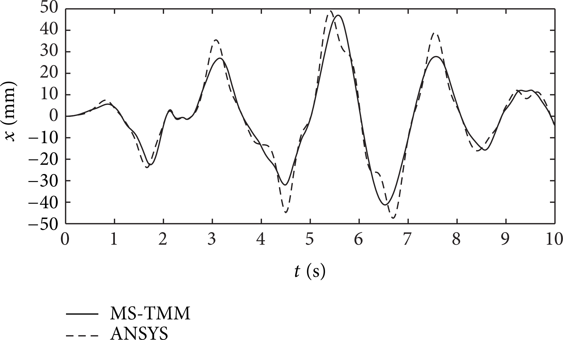
Displacement time history curves for the top of column B during a rare earthquake.
The maximum displacements and elastic-plastic story drift angles for the tops of columns A and B during a rare earthquake obtained by MS-TMM and ANSYS are listed in Tables 6 and 7, respectively, and the errors between these two methods are also listed.
Maximum displacements for the top of column A during a rare earthquake.

Maximum displacements for the top of column B during a rare earthquake.

As listed in Tables 6 and 7, the trends of the displacement time history curves obtained by MS-TMM and ANSYS are similar, and the maximum elastic-plastic story drift angles are approximately 1/100 in both methods, which meet the requirements of seismic resistance. The maximum displacements for the tops of the columns obtained by these two methods are similar with a maximum error of 9.69%, which is in accordance with the engineering precision. The calculation time of the MS-TMM method was approximately 1/30 that of the ANSYS method, which reflects the high calculation efficiency of the MS-TMM method.
Additionally, the shapes of the displacement history curves for the tops of columns A and B are similar and nearly reach their maximums at the same time: the latter value is shown to be slightly smaller than the former.
4.3.3. Analysis of the Shear Force on the Bottom of the Column of the Portal Frame Structure
The shear forces on the bottom of columns A and B during a rare earthquake based on MS-TMM and ANSYS are shown in Figures 12 and 13, respectively.
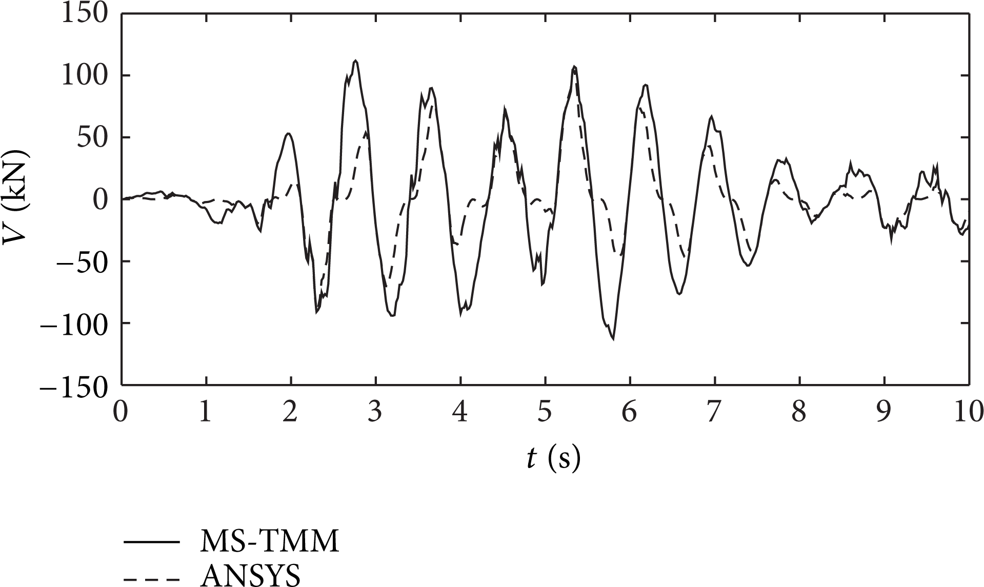
Shear force time history curves for the bottom of column A during a rare earthquake.

Shear force time history curves for the bottom of column B during a rare earthquake.
The maximum shear forces on the bottoms of columns A and B during a rare earthquake obtained by MS-TMM and ANSYS are listed in Tables 8 and 9, respectively, and the errors between these two methods are also listed.
Maximum shear forces on the bottom of column A during a rare earthquake.

Maximum shear forces on the bottom of column B during a rare earthquake.

As listed in Tables 8 and 9, the trends of the shear force time history curves obtained by MS-TMM and ANSYS are similar, the maximum values are similar, and the maximum error is 8.17%. The calculation time of the MS-TMM method was approximately 1/30 that of the ANSYS method, showing a greatly improved calculation speed.
5. Conclusion
In this paper, the transfer matrix method of a multibody system was established as a mechanical model of a portal frame structure, where its characteristics were used to derive the transfer matrices of the elements in the model and obtain the total transfer equation. As a practical example, the structure's natural period and seismic response during common and rare earthquakes were analyzed. The results from the analysis based on the MS-TMM method were then compared to those based on the traditional ANSYS method, and the following conclusions were drawn.
The first five order natural periods of the portal frame structure obtained by the two methods are similar, showing a maximum error of 14.87%. The calculation time of the MS-TMM method was shown to be approximately 1/7 that of the ANSYS method.
During a common earthquake, the maximum elastic story drift angles of the top of a column obtained by the two methods both meet the requirements of the code for seismic design. The maximum error of the displacements for the top of column was 2.31%, the maximum error of the shear force for the bottom of column was 2.63%, and the calculation time based on the MS-TMM method was approximately 1/15 that based on the ANSYS method.
During a rare earthquake, the maximum elastic-plastic drift angles of the top of a column obtained by the two methods both meet the requirements of the code for seismic design. The maximum error of the displacements for the top of column was 9.69%, the maximum error of the shear force for the bottom of the column was 8.17%, and the calculation time based on the MS-TMM method was approximately 1/30 that based on the ANSYS method.
Conflict of Interests
The authors declare that there is no conflict of interests regarding the publication of this paper.