
Abstract
Quick calculation of machine tool dynamic response represents one of the major requirements for machine tool virtual modelling and virtual machining, aiming at simulating the machining process performance, quality, and precision of a workpiece. Enhanced time effectiveness in machine tool dynamic simulations may be achieved by employing model order reduction (MOR) techniques of the full finite element (FE) models. The paper provides a case study aimed at comparison of Krylov subspace base and mode truncation technique. Application of both of the reduction techniques for creating a machine tool multibody model is evaluated. The Krylov subspace reduction technique shows high quality in terms of both dynamic properties of the reduced multibody model and very low time demands at the same time.
1. Introduction
In recent years, with increasing computational power of computers, machine tool virtual modeling has become one of the intensively developed tools for simulating the machine tool behavior in interaction with machining process, aiming especially at predicting the machining performance, process quality, and stability [1–4]. A key element in machine tool dynamic behavior represents the compliant machine tool mechanical system, including both the structural parts and the components of feed drive systems as well. Excitation of natural eigenfrequencies of the machine tool mechanics stands in the foreground of problems and represents one of the limiting factors related to enhancing the machining performance, since it can lead to either deteriorated machined surface quality, workpiece precision, or even generation of instable machining process.
The modern machine tool, as a typical mechatronic system, features a number of interactions between the control and mechanics [5]. Achievable parameters of both the CNC control and feed drive control as well relate directly to mechanical eigenfrequencies and damping of the mechanical system. Commonly, the setting of the control parameters is defined by the most compliant configuration of the machine tool mechanics, and thus the potential of the structural dynamics with respect to control remains not fully utilized. In the case of ball screw driven motion axes, the above mentioned issue relates predominantly to active length of the ball screw. Next to it, structural modal properties of large machine tools may vary significantly also depending on the kinematical configuration and actual position of the motion axes.
Relevant capturing of the machine tool structural properties represents an important tasks in virtual modeling. Coupled modeling techniques employing the reduced FE models of the machine tool structure have been developed for describing the ball screw feed drive and machine tool interaction. Commonly the coupled models rely on one kinematic configuration and application of modal or CMS reduction techniques [6–9]. Importance of proper prediction of higher frequency range dynamics of feed drive mechanical structure with respect to feed drive control parameters shows [10]. Using the coupled models, machining process stability and performance may be predicted by the oriented directional frequency response functions (FRFs) at tool center point (TCP) [11].
For updating of machine tool structural modal properties, a technique based on continuous redistribution of contact force along the motion axis linear guideway has been developed in [12]. Another approach employing an additionally created FE node moving between the end positions of the motion axes stroke has been described in [13].
The finite element method (FEM) is used as a common way to simulate the dynamic behavior of a machine tool. The solution of FE problems usually involves the solution of a large set of sparse algebraic equations. The number of unknowns in ordinary engineering FE model nowadays is commonly 106-107. The computational time needed to solve static analysis of such problems on current hardware is acceptably low (∼hours). The issue arises when the harmonic or transient analysis is required. The solution then requires 10's or 100's of iterations and therefore requires days or even weeks to solve. Such long solution time effectively hinders this kind of simulations in machine tool virtual model simulations. The model order reduction (MOR) methods are one of possible ways to speed up the solution and make it feasible in practice. The idea behind MOR is to reduce the number of unknowns while producing sufficiently good approximation to the input/output behavior.
The following text gives a basic review of model order reduction techniques. The idea of reduction of the number of unknowns during the solution of the FE model is almost as old as the FE method itself. The first MOR method was static reduction proposed by Guyan [14] and Irons [15]. This method was introduced for structural mechanics problems but it is also valid for thermal analysis and other analyses regardless of the underlying physics. However, this method is of questionable quality when using it for dynamic analyses as was shown in [16, 17].
To remedy the insufficiencies in the static condensation method, the component mode synthesis (CMS, [18]) was proposed by Bampton and Craig. The CMS has become widely used by the engineering community. The CMS was used to efficiently conduct not only large-scale structural eigenanalysis [19] but also transient heat conduction analysis [20] and heat conduction/convection analysis [21]. Another field of application of the CMS is coupled physics simulations. The weakly coupled thermomechanical models were studied in [22]. There is still active research regarding improvement of the CMS [23].
Another method enhanced to approximate dynamic systems well is the improved reduced system (IRS) proposed by O'Callahan in [24]. Later, Friswell et al. developed an iterated version of IRS in [25]. The static condensation, CMS, and IRS can be viewed as engineering approaches to reduce the number of equations.
The global error bounds and the preservation of passivity and stability are important questions posed on the MOR methods in a more mathematical point of view. Two of the MOR techniques proposed in accordance with these questions are Krylov subspace reduction [26] and Balanced truncation [26]. Balanced truncation methods [27] have a great advantage because there exists a priori global error bound. But it also has a great disadvantage in that the Lyapunov equation [28] needs to be solved in order to reduce the system. Thus the usage of balanced truncation in reduction of large-scale systems is limited.
The Krylov subspace methods [26, 29–31] are very interesting because of their iterative nature which allows the reduction of large-scale problems. The computational efficiency of Krylov subspace based MOR has encouraged wide interest in the method, and therefore wide knowledge in different fields is available. We will mention the most important observations to date. The passivity and stability preservation has been achieved using the Krylov MOR methods in [26, 32]. A Krylov algorithm preserving structure of second order ordinary differential equations has been presented in [33]. Handling of nonlinear convection coefficient was studied in [34]. Reduction of coupled physics problems was studied in [35] for the case of a thermomechanical model of packages and in [36] for the case of structural-acoustic coupled models. Krylov subspace MOR was also successfully used in optimization of MEMS devices [37] and sensitivity analysis of structural frequency response [38]. One of the most important directions in development on the Krylov base reductions is a parametric model order reduction (PMOR). The PMOR allows preservation of parameters which the system depends on [39, 40]. The dependence of parameters may be either linear or nonlinear.
The comparison of different model order reduction methods has been discussed in [17], where the Krylov subspace MOR method was found to be one of the best methods. The comparison of Krylov, CMS, and balanced truncation can be found in [41].
Based on the findings presented in previous works the Krylov subspace based MOR is very robust and computationally efficient. The goal of this study is to show a new strategy of employing the Krylov MOR technique for creating the coupled models of compliant systems. The idea is to reduce each part of the machine tool structure separately and to produce the coupled model of the whole assembly. This way enables coupling of reduced components in any kinematic configuration. To assess the quality of Krylov MOR and to show its soundness the following comparison properties will be evaluated:
low error in approximation,
fast computation.
A low error in the approximation of a full FE model is required, as the objective is to replace the full FE model in simulations. Fast computations are required to meet the requirements in virtual machine tools simulations.
The proposed procedure will be tested on industrial scale (106-107 DOFs) FE model of machine tool. The harmonic and transient simulations on such large models take a lot of time (days, weeks), and therefore some kind of acceleration is usually used. Mode truncation [42] is frequently used for fast simulations and will be compared with Krylov based MOR. Both methods will be employed in reduction of individual parts of machine tool. The reduced part will be then coupled in any kinematic position. The purpose is to simulate flexible multibody systems accurately and very fast (with possible applications in real-time CNC control simulations). The proposed method of coupling the Krylov based reduced substructures has not yet been reported in the literature, to the best the authors’ knowledge.
The paper is organized in the following way: Section 1 contains the introduction and the motivation of work; approach to substructuring is considered in Section 2; Section 3 contains the description of Krylov subspace reduction; Section 4 introduces the used machine tool model; and Section 5 presents the comparison of the results obtained by the methods. Conclusion suggestions on future work are given in Section 6.
2. Substructuring
One way to couple dynamic systems is to connect their mass

The matrices
Consider
The compatibility condition (coupling equations) is expressed as

Equilibrium condition is given by
where
Equations (1), (2), (3), and (4) can be now used to couple any number of subsystems. Before it can be done, however, the unknown interface forces have to be eliminated:

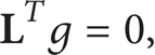
Here xu is a vector of unique DOFs. Because (5) indicates that the substructures DOF are obtained from the unique set xu, the compatibility equation (3) is satisfied for any set xu:
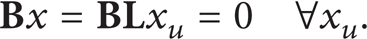
This means that

Substituting (5) into (1), one gets equation of motion
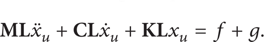
Further multiplication of (8) from the left-hand side by

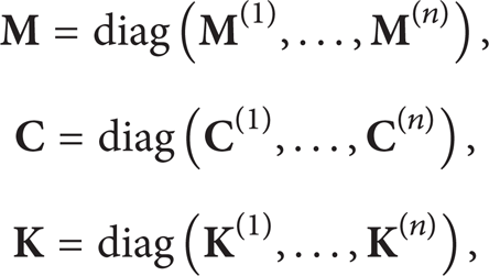
where matrices

Coupling of Reduced Components. Let us consider the case of n independent substructures, each reduced using projection matrix

where x are physical coordinates of substructures and η are generalized coordinates of substructures. Substituting (11) into (1) we get

where r(s) are residual forces due to model order reduction. Following Galerkin method, we enforce

where

Then following, procedure for coupling full matrices (3)–(10), we get coupled reduced system. This procedure allows reducing substructures independently and then coupling of reduced systems. The coupling interface is defined using matrix
3. Model Order Reduction Methods of Second Order Systems
The underlying physics of the problem is described by a system of linear second order ordinary differential equations with constant coefficients
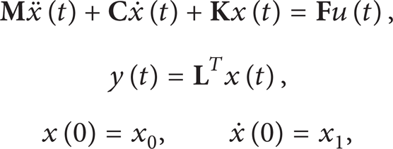
where x(t)∈R
N
is displacement vector of state variables, u(t)∈R
N
is input function, and y(t)∈R
m
is output function. The matrices
3.1. Mode Truncation
One of the less complex methods of model order reduction is modal truncation method [42]. The projection matrix
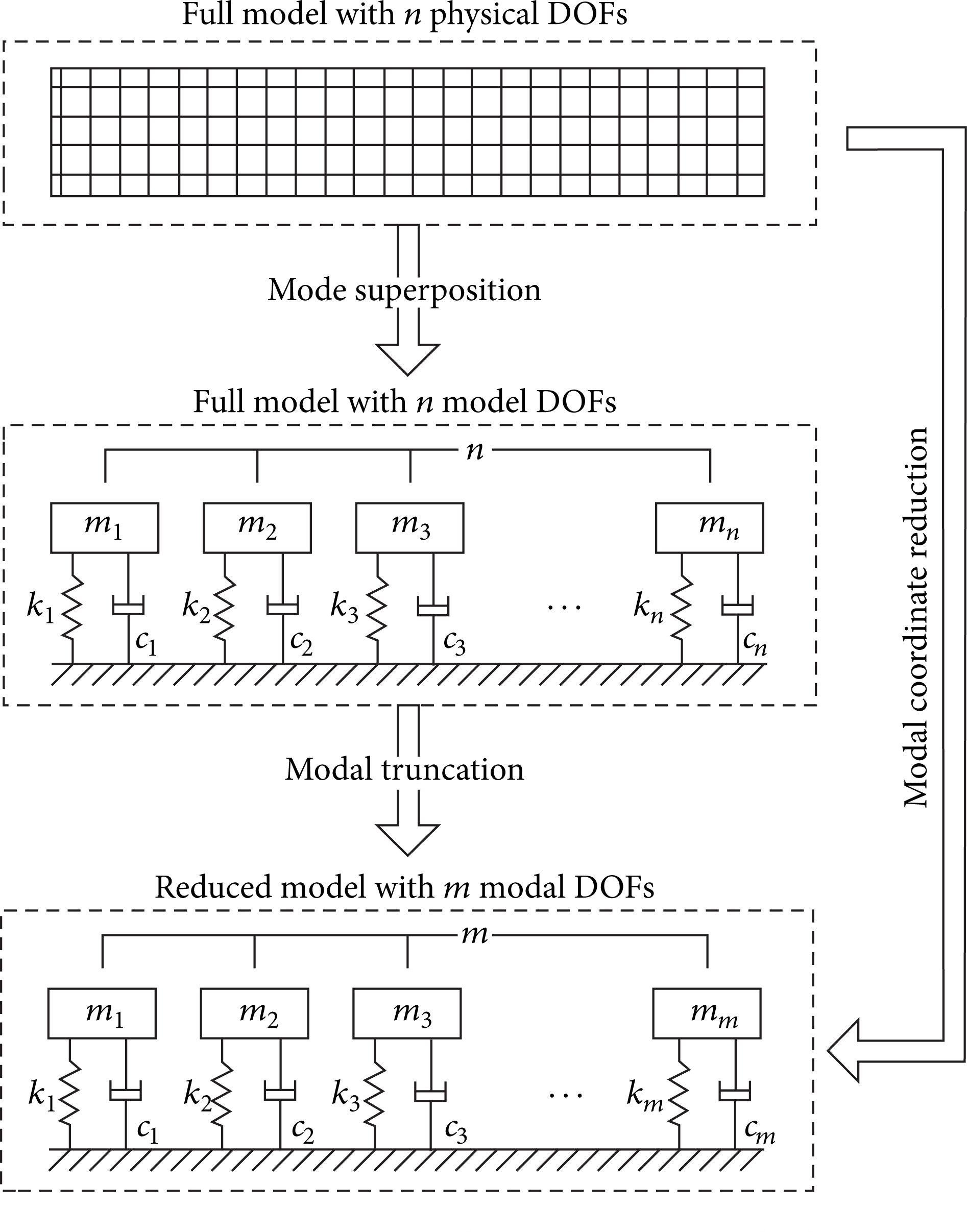
Diagram of modal truncation [42].
The equation of motion of the full model is

where
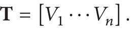
The projection matrix
The vector x can be transformed to vector of modal coordinates using

This equation can be then substituted to (16) and after multiplying the result by

where
The model order is reduced by including only a small number of mode shapes and degrees of freedom in (19). The number of mode shapes included depends on the required accuracy of the reduced model. It is recommended that the natural frequency of the last included mode shape is at least twice as high as the highest working frequency of the resulting reduced model. The number of included DOFs does not affect the model accuracy so only the important ones are included.
One disadvantage of this method is the fact that the reduced model's FRF never fits the full model's FRF near 0 Hz. Another drawback is the relatively long time needed to create the reduced model (modal analysis with extraction of lots of modes has to be performed). The method is on the other hand simple and accurate in chosen frequency range.
3.2. Krylov MOR
In this section only the basics behind Krylov reductions will be described. The reader is encouraged to read an excellent mathematical description of Krylov based reductions in [26]. An overview of the reduction methods is given in [27]. Although optimal Krylov based reduction algorithms are available [44], a simpler and a possibly more computationally efficient method will be used in this work—a block rational Krylov method [45]. The structure of second order ODEs in (15) will be preserved using Bai's algorithm [33].
3.2.1. The Treatment of Initial Conditions
Let us consider using the following coordinate transformation in case of (15):


Right-hand side of (21) is enriched with the constant term -

This kind of treatment of a nonzero IC was introduced in [46].
3.2.2. Krylov Subspace Based MOR
The Laplace transform of (15) has the form of
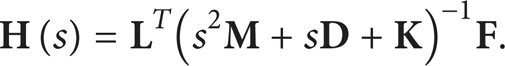
And the McLaurin series of transfer function (23) has the form

where ml are the so-called moments of the transfer function
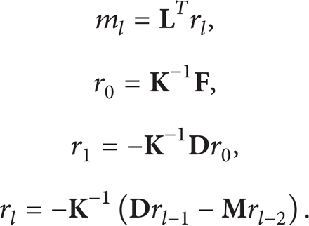
The first n vectors rl span Krylov space

Letting

The projection of state coordinates x onto

The error ϵ∈R
n
in the projection rises while performing projection of x onto
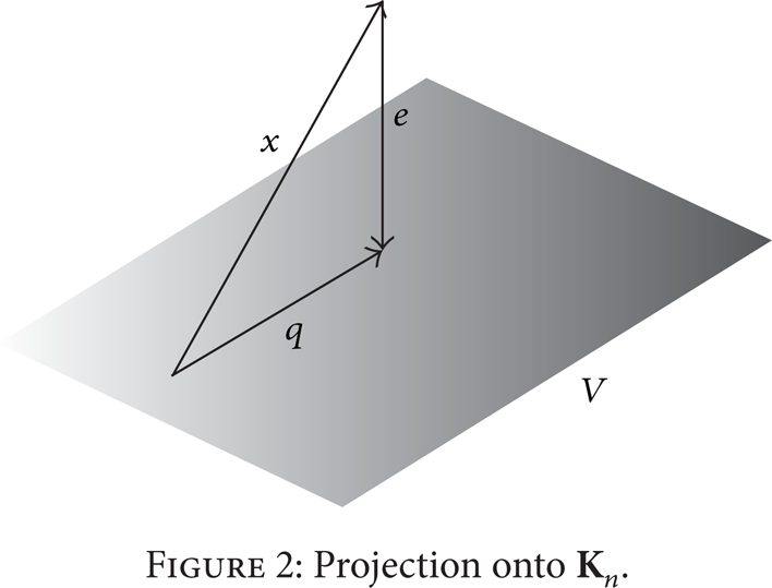
Projection onto
We obtain reduced system of (29) by substituting generalized coordinates q into (15) and using the Galerkin method. The reduced equations have the form of

where

where
The transfer function of the reduced system (30) has the form

The above procedure assures that the first n moments of the transfer function (23) of the full system equal the first n moments of the transfer function (31) of the reduced system [26].
The error induced by the projection (28) in the output function y(t) has the form

An a priori expression for error norm (32) is not known although there exist algorithms minimizing the error [44, 47]. The algorithm used in this paper to produce the reduced order systems is the block Arnoldi algorithm [45].
There exist wide possibilities to improve the computational performance of Krylov methods. One of the most obvious options is parallelization [48]. Another is to use an iterative algorithm to solve the system [49]. The presented case is of medium size, and it is therefore suitable to use the direct sparse solver [50].
The procedure is easily extended to a multi-input/multi-output case where
4. Machine Tool Model for the Case Study
The dynamic performance of a machine tool may be evaluated at the TCP using the oriented directional FRFs, which directly relate according to stability theory to achievable chip thickness [52–54]. FRF can be obtained by harmonic simulation of either a full FE model or reduced models.
The purpose of the study is to perform mathematical verification of the FRFs generated at the TCP using a full FE model, or reduced order models. Modal reduction technique and Krylov subspace method are considered. At the same time, the study aims at testing the suitability of reduction methods for creating a machine tool multibody model, assembled from reduced FE models of separate structural parts. In this way, a model allowing for quick update of machine tool dynamic properties according to actual kinematic configuration is created.
A model of a large portal milling machine tool is considered. The FE model (Figure 3) consists of the volume, shell, spring, matrix, and mass elements. The mesh consists of about 1,5·106 nodes; the total number of degrees of freedom number is almost 6·106. The model was built in ANSYS v 14.5. Linear guideways are represented by linear spring elements; similarly the rack and pinion feed drives are modeled using linear spring elements, which reflect the closed position control.
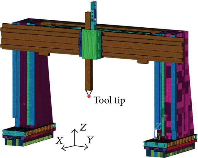
Machine tool FE model.
Figure 4 shows the decomposition of the FE model into separate structural parts with a description of the type of coupling chosen according to the character of connections between the parts. The parts are connected either through the faces—typically, for example, connection of the column with the X-slide (face coupling)—or by force interaction in the case of linear guides (symbols of springs in Figure 4).

Multibody system of the machine tool structure.
5. Results
The following case studies compare computational efficiency of full harmonic in ANSYS software package and model order reduction using mode truncation and Krylov MOR. To assess the quality of results obtained using MOR the error norm is evaluated. The study is performed in one kinematic configuration, and it is assumed that properties of MOR techniques will be similar in other kinematic configurations. The model used in the study is a multibody system.
5.1. The Harmonic Simulation of Machine Tool
The frequency response function at the tip of the tool has been computed using a full FEA model and MOR using mode truncation with first 100 modes for each reduced component and Krylov subspace MOR with first 100 moments. Additionally FRF computed using modal reduction is provided for comparison. The comparison is shown in Table 1. The error norm is concluded to be

The Table 1 shows comparison of methods in terms of time needed to produce the reduced order model, time needed to computed FRF, and total time. The time needed to produce coupled reduced components is added to the time required to compute FRF. The reduced models are computed only once and then it is possible to couple them in any kinematic configuration. The coupling is computationally very cheap.
Comparison of computational times.

Figures 5 and 6 show FRFs in axes x and y. The results clearly show the quality of approximation obtained using Krylov MOR as well as computational efficiency compared to the full solution and modal reduction. The Krylov MOR is about 1000x more computationally efficient than the full solution, and the approximation error is almost negligible. The mode truncation is computationally less efficient and also the approximation error on frequencies higher than 50 Hz is very high rendering this method almost unusable.
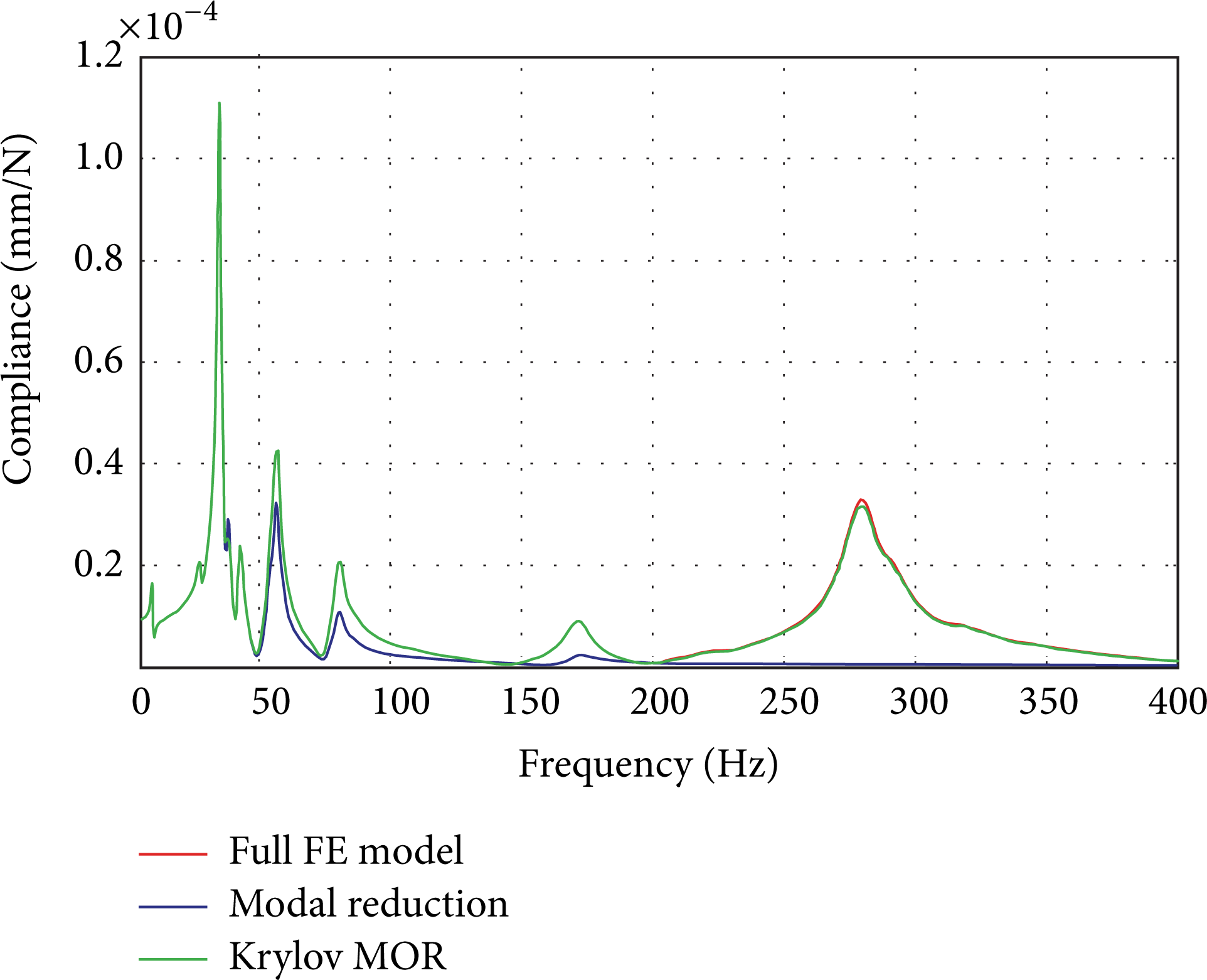
Comparison of FRF, X-axis.

Comparison of FRF, Y-axis.
6. Conclusions
In the paper a novel application of Krylov subspace based model order reduction method for coupling of compliant components, modelled as FE bodies, has been proposed and successfully tested. To the best of the authors’ knowledge, coupling of arbitrary substructures reduced using Krylov MOR has not yet been reported in the literature. The proposed method has been tested on a dynamic simulation of multibody system of the machine tool structure.
The case study has shown superior quality of the Krylov subspace based MOR in comparison to mode truncation technique for creating the machine tool multibody model, in which each of the structural parts is reduced separately and coupled to each other using either faced, or force coupling. The multibody model employing the Krylov subspace base MOR features almost identical match of the dynamic properties with the full FE model. At the same time, Krylov subspace method is very time efficient and proves to provide a very effective tool for quick model updates related to varying structural dynamics with respect to various kinematic configurations or testing of different design variants in the machine tool development. The Krylov subspace will be next used for creating a multibody model with movable motion axes. Precise capturing of the varying dynamic properties will improve the quality of tool oscillation simulation and will help increasing the accuracy of machined surface quality and workpiece precision in virtual machining. Low time requirements of the Krylov subspace reduction technique set also a good prerequisite for possible future real-time applications of machine tool dynamic virtual model as an observer in a real CNC control.
Conflict of Interests
The authors declare that there is no conflict of interests regarding the publication of this paper.
Footnotes
Acknowledgment
This research has been supported by the Competence Center-Manufacturing Technology Project TE01020075 funded by the Technology Agency of the Czech Republic.