
Abstract
An ejection aperture nozzle is the essential part for all microdrop generation techniques. The diameter size, the flow channel geometry, and fluid impedance are the key factors affecting the ejection capacity. A novel low-cost fabrication method of microglass nozzle involving four steps is developed in this work. In the first heating step, the glass pipette is melted and pulled. Then, the second heating step is to determine the tip cone angle and modify the flow channel geometry. The desired included angle is usually of 30~45 degrees. Fine grind can determine the exact diameter of the hole. Postheating step is the final process and it can reduce the sharpness of the edges of the hole. Micronozzles with hole diameters varying from 30 to 100 µm are fabricated by the homemade inexpensive and easy-to-operate setup. Hydrophobic treating method of microglass nozzle to ensure stable and accurate injection is also introduced in this work. According to the jetting results of aqueous solution, UV curing adhesive, and solder, the fabricated microglass nozzle can satisfy the need of microdroplet jetting of multimaterials.
1. Introduction
Micronozzles are becoming increasingly important in all microdrop generation techniques. The diameter size, the flow channel geometry, and fluid impedance are the key factors affecting the ejection capacity [1–8]. Each application requires an optimal shape and size for micronozzles; hence a controllable fabrication process is extremely desirable [9–13]. Currently, micronozzles have been made by several methods including micromechanical drilling, laser drilling, electroforming over a sacrificial post, electron beam machining, electrodischarge machining, lithography and etching, deep reactive ion etching (DRIE), LIGA process, and bulk-silicon etching [14]. The method of traditional microdrilling is difficult to make a hole which has tens of microns in diameter. The IC technology with photolithography and etching can make submicron holes on silicon, but this method has high demand on the environment and cannot be under routine conditions because of intricate steps. Moreover, the method is of high cost and is time-consuming on small-lot production. Laser drilling, DRIE, and LIGA mold process require several steps and are difficult to fabricate micronozzles having different feature sizes of the bottom and the top diameters. Bulk-silicon etching can provide a micronozzle with a constant side slope determined from the angle between the exposed crystal planes, but the reaction condition is very tough. In addition, the shapes of blue sapphire and ruby nozzle can be precisely controlled in its production process, but the price is very expensive [15–18]. Generally, the currently employed methods are of varying degrees of cost and complexity and are time-consuming to fabricate microdrop ejection nozzles. Fabrication of microstyluses by the glass tube for surface form methodology is a simple and effective method [19].
In this paper, a novel low-cost fabrication method of microglass nozzle involving four steps is developed. Micronozzles with hole diameters varying from 30 to 100 μm are fabricated by the homemade inexpensive and easy-to-operate setup. In addition, hydrophobic treating method of microglass nozzle to ensure stable and accurate injection is introduced in this work. Using the system configured with the fabricated microglass nozzle, the microjetting results of multimaterials including aqueous solution, UV curing adhesive, and solder are satisfactory.
2. Fabrication Process of Microglass Nozzle
The formation of microdroplet is inextricably associated with the physical properties of the jet liquid and the geometry of the micronozzle. Figure 1 shows the schematic of glass micronozzle. D is the inner diameter of the glass tube, d is the inner diameter of the micronozzle, L is the length of the micronozzle, and α is the contraction angle. For maintaining jet stability, turbulent flow should be avoided. When the flow in the tube remains laminar, the value of L/d required is related to the Reynolds number as L/d = 0.057Re. The contraction angle α possesses attractive performance characteristics. Generally, the optimum α varies from about 100° for low velocities to about 30° for very high flows. For the self-made ejector, the desired included angle is usually of 30~45° [20].

Schematic of glass micronozzle.
Borosilicate glass pipette is used to produce micronozzle and its compositions are shown in Table 1. The advantages of borosilicate glass are as follows: (1) excellent chemical stability, corrosion resistance to almost all the acids and alkalis except hydrofluoric acid, concentrated alkali, and concentrated sulphuric acid, (2) smooth surface and a low fluid impedance, (3) easiness of processing above the softening point of 770 ± 10°C, (4) good optical characteristics, transparent glass which is beneficial for real-time monitoring of the nozzle diameter and the generation status of microdroplet by CCD image processing system, and (5) low cost and good durability.
Borate glass composition.

Figure 2 shows the whole process steps to obtain microglass nozzle. In the first heating step, the glass pipette is melted above softening point and then pulled. The micronozzle with the sharp tip and the long flow channel comes into being. Then, the second heating step is to determine the tip cone angle and modify the flow channel geometry. The desired included angle is usually of 30~45°. Now, the tip of the nozzle is closed. Fine grind can determine the exact diameter of the hole. Postheating step is the final process and it can reduce the sharpness of the edges of the hole.

Manufacturing flow of glass micronozzle.
2.1. First Heating
The purpose of the first heating is to obtain the desired abrupt cone of glass tube. The glass is heated to the melting point where separation and construction of the end occur. Under the axial tension, the heating coil was set at the right place so that the appropriate heating will result in an abrupt separation of the glass tube into two halves each with a short conical end. The key control parameters are heating current, the diameter of heating coil, and the pulling force.
Figure 3 is the puller setup for producing a conical end on a glass pipette, which consists of a fixed chuck, movable chuck, heating coil, linear guideway, linear bearing, and weight. The fixed clamp and the movable clamping are connected through linear bearings and linear guideway on both sides and can move up and down smoothly. The bottom of the movable chuck has a tray, which can load different weights. The heating coil made of nichrome wire wound about three circles is fixed on the pedestal between the fixed chuck and the movable chuck. When the heating coil is electrified, the glass tube will be melting and separated into two halves under the gravity of weight. How to adjust the parallelism of the heating coil and the glass tube is very important to ensure the symmetry and the uniformity of the flow channel. We adopted the following methods. Firstly, the equipment base is set for datum place. Glass tube fixture was precisely designed and adjusted to ensure the perpendicularity between the glass tube axis and datum place. Secondly, heating coil has good cylindricity; the transverse plane is parallel to the datum plane. When the gap between glass tube and heating coil is uniform, the axiality will be good. The above method can guarantee the uniformity of heat.

Low-cost puller setup for producing a tapering end on a glass pipette.
A DC regulated power (Lv Yang YB1730 A–20 A) is supplied in the puller system. The heating current directly affects the softening and deformation of the glass tube. Figure 4(a) shows the result of applying 16.7 A on 6.5 mm diameter glass tube. It is evident that the heating current is too low to separate the melting pipette. Upon a lot of trial and error handwork, the appropriate temperature range can be found out as 16.8~17.4 A. Figure 4(b) shows the separated tapering part upon 17.3 A, 17.2 A, and 17.1 A, from top to bottom. Obviously, the lengths of flow channel decrease along with the decrease of the heating current. On the contrary, the contraction angle α will increase accordingly. In addition, improper installation may lead to some problems. As shown in Figure 5, no matter whether it is noncoaxial or aslant installation of the heating coil and the glass pipette will lead to deflection of the flow channel and surface defects.
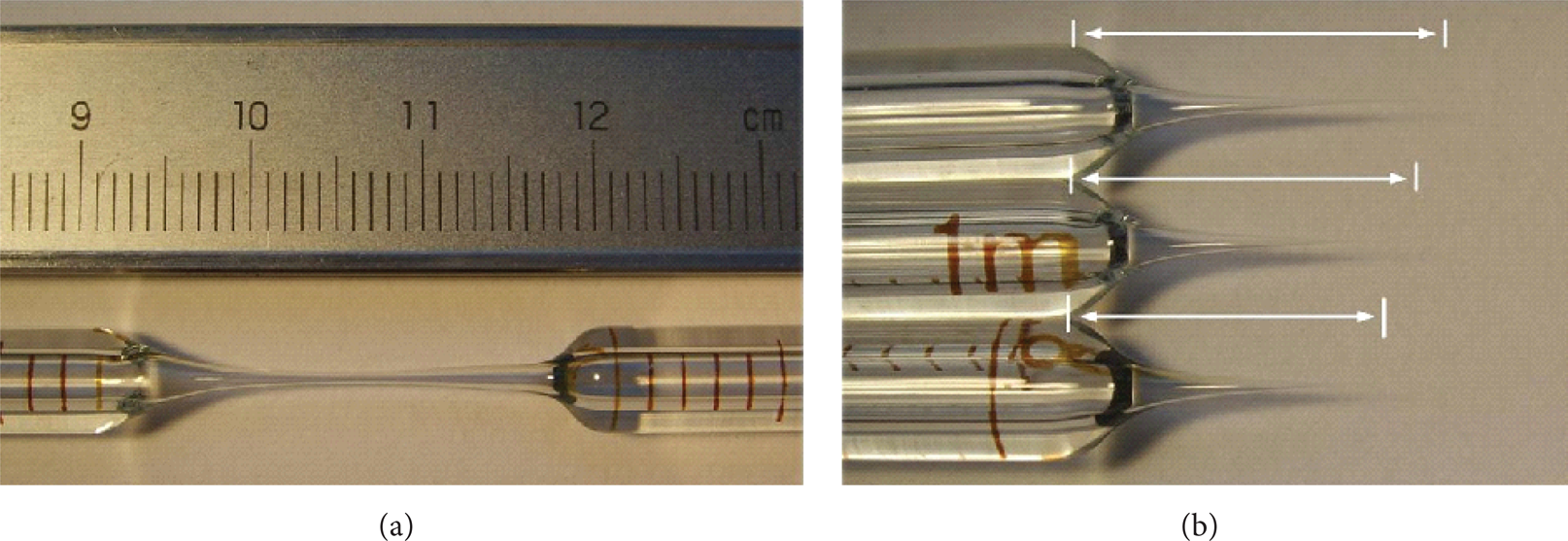
Results of pulling under different heating currents.

Micronozzle with oblique axes when the pipette is installed aslant.
The result of the first heating step of the puller produces in the glass tube a long, sharp, tapered, and open-ended geometry to the pipette. Figure 6 shows that the tip is not closed. The inner diameter of microneedle is 1 μm and outer diameter is only 1.5 μm. It is not suitable for acting as a microdrop generator nozzle. The reasons are as follows: (a) the longer the flow channel, the larger the flow resistance, leading to the more driving force to overcome flow resistance; (b) the outlet wall thickness of nozzle is too small to avoid damage. Therefore, the micronozzle is necessary to be further processed.

Microscope photograph of the conical tip of a pulled pipette after the first heating step.
2.2. Second Heating
The purpose of the second heating step is to shorten the flow channel for reducing the flow resistance and ensure the right injecting direction. Figure 7 shows the second heating setup consisting of locating device, fixture, and heating coil. During heating, the tip will remelt and close; then the desired cone angle will be modified to 30~45 degrees. The whole process is monitored by a microscope. Figure 8 shows the microscope photograph of the closed conical tip after the second heating step. The tip is a closed off sharp cone.
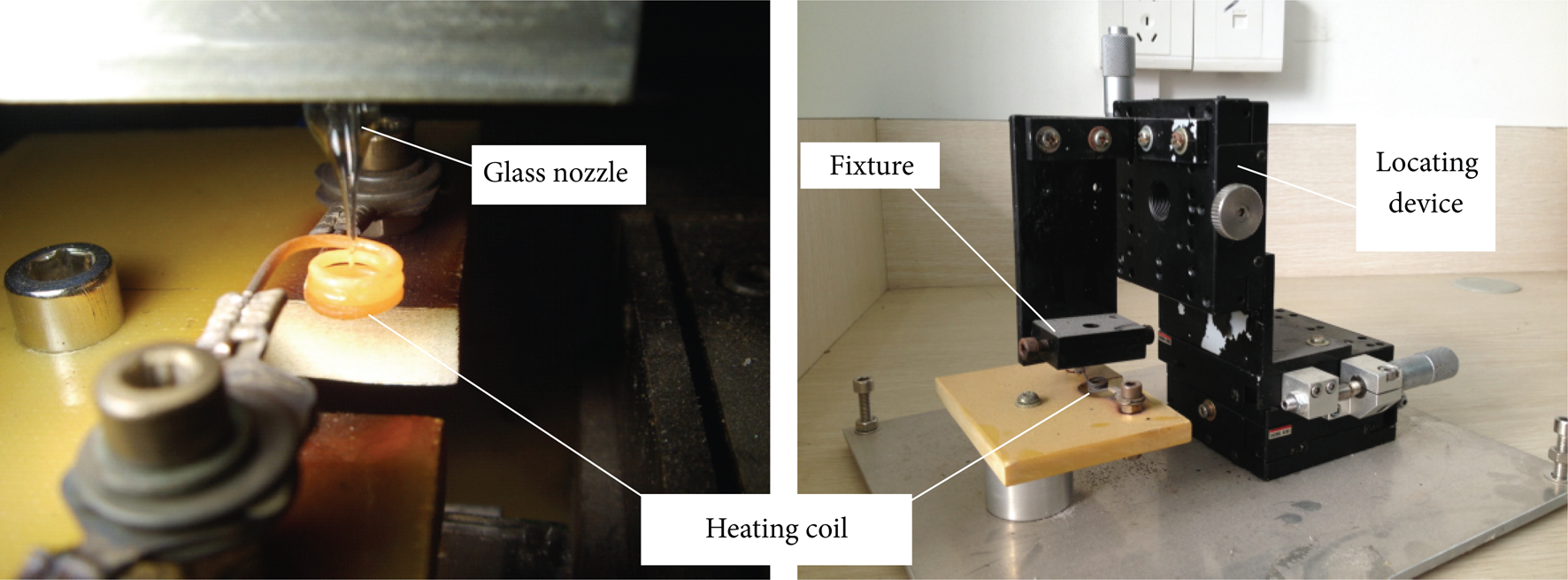
Second heating setup.

Tip of the pipette after the second heating step. (a) ×50. (b) ×150.
2.3. Fine Grind
The fine grind setup to controllably cut back the tip is constructed using a grinding wheel, a V groove alignment block, and a locating device, as illustrated in Figure 9. The exit hole is formed by grinding back the tip until a hole of the desired diameter is exposed. Grinding the glass sealed end to a precise prespecified diameter is a very delicate operation technique. The exact diameter of the hole is obtained by directly observing the hole in the tip with a microscope. The grinding wheel is a 10 cm diameter sanding disc with the grain size of 150. The V groove block holds the glass pipette in a perpendicular alignment to the sanding disc. Figure 10 is the outlet of micronozzle after fine grind.

Fine grind setup.
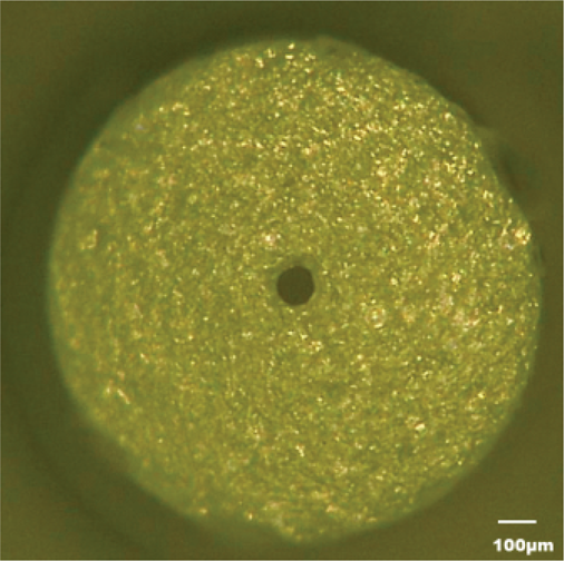
Outlet of micronozzle after fine grind.
2.4. Postheating
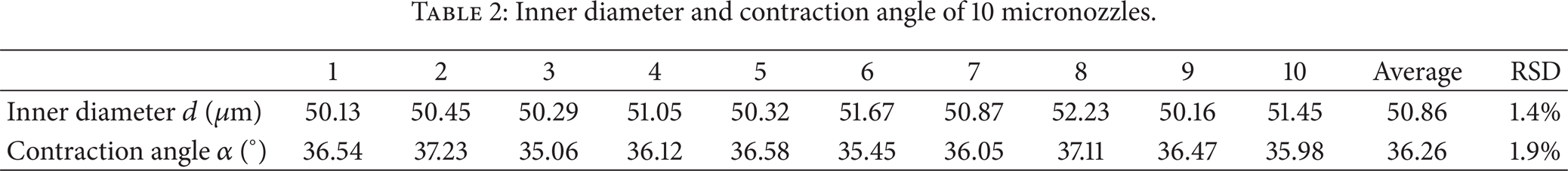
The tip can then be postheated to reduce the sharpness of the edges of the hole outlet. As the tip is heated to melt the glass in order to polish the surfaces, the diameter of the hole also contracts and the end starts rounding off. Postheating the tip is a very tricky process and easily ruins the tip. The amount of heating necessary to reduce the roughness of the hole is very small. Placing the tip in the high temperature region of the heating coil for several seconds is sufficient. Overheating the tip will close off the glass nozzle tip again. The postheating step is also accomplished using the second heating setup shown in Figure 7. Figure 11 is the end result of micronozzles fabricated through all steps. Inner diameters and contraction angles of ten micronozzles are measured by three-dimensional optical microscopy of ultradepth of field (Keyence, VHX-600E). From the data as shown in Table 2, we could obtain the average and the relative standard deviation of the inner diameters as 50.86 μm and 1.4%; the same values of the contraction angles are 36.26° and 1.9%.
Inner diameter and contraction angle of 10 micronozzles.

Finished nozzle.
3. Hydrophobic Treating of Microglass Nozzle
Wetting of the nozzle surface can seriously influence the operation of drop generators for multiple reasons. The first is that excess fluid buildup may suppress microdrop ejection. Another issue is that asymmetric fluid buildup on the surface of the ejection orifice may deflect the direction of drop ejection. The deposition of antiwetting thin films is one common technique used to reduce ejection orifice fluid buildup around the ejection hole. Antiwetting surface films reduce the fluid accumulation over the nozzle by modifying the fluid-surface contact angle. A high contact angle indicates a surface on which the fluid drops tend to form small mobile spheres. On the contrary, fluid drops on the low contact angle surface would wet the surface forming a thin film spread out over the surface. The features can be used to suppress wetting of the ejection aperture surface by coating the surface with a high contact angle thin film while keeping the interior of the nozzle with low contact angle.
Fluoropolymers are the most common high contact angle coatings. The coating fluid is true solution. It has sufficient adhesion and uncured surface smoothness to function well even without thermal curing. Contact angle for water is from 120° to 170°. The thickness of the film is on the order of a few microns. A dip method is used to apply fluoropolymers thin films to objects. The pressurized air coming out of the nozzle hole prevents this passage from being blocked.
For the nonhydrophobic nozzle, the fluid will gradually accumulate over the ejection hole and form a droplet with the diameter considerably larger than the nozzle hole upon insufficient driving force. Until the gravity is greater than the surface tension, the droplet will fall down to form a sphere, as Figure 12 shows. When applying enough driving force, the microdroplet about 120 μm in diameter will come into being by overcoming the liquid film resistance, as Figure 13 shows. However, the required pressure is larger in this case, and the diameters of formed droplets have poor repeatability. Figure 14 shows ejection process of a single 92 μm diameter microdroplet from a hydrophobic nozzle.
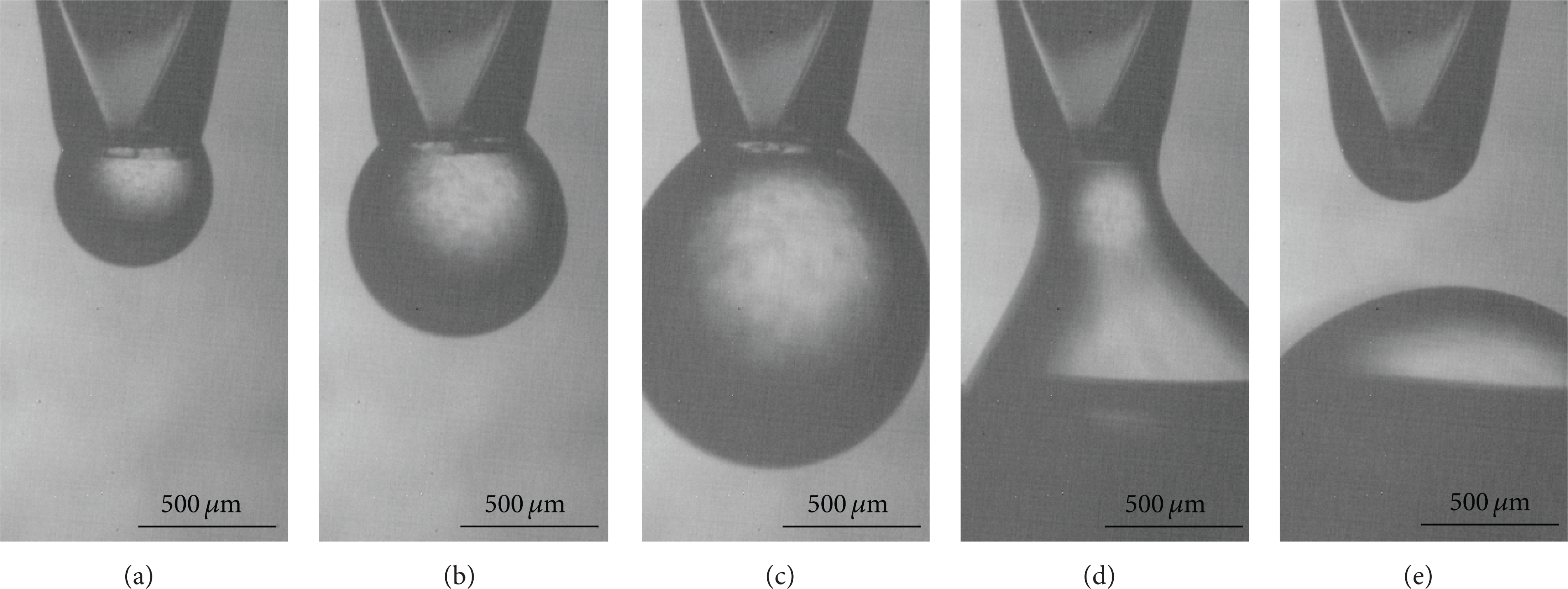
Accumulation process of a microdroplet from a nonhydrophobic nozzle.

Ejection process of a single microdroplet from a nonhydrophobic nozzle.

Ejection process of a single microdroplet from a hydrophobic nozzle.
4. Results of Microdroplet Jetting
4.1. Ejection Process of a Single Microdroplet
The ejecting process was performed using the homemade drop-on-demand inkjet system based on pneumatic diaphragm actuator [7]. Table 3 lists the controlled parameters. The general fluid property requirements for a fluid to be used in microjet device are as follows: viscosity belongs to 0.5–40 mPa·s and surface tension belongs to 20–70 mN/m. Figure 15 describes the ejection process of a single microdroplet with the diameter of about 300 μm. The liquid is glycerin/water (60/40, mass ration), and the viscosity and surface tension are 10.0 mPa·s and 69 mN/m, respectively. Time lapse images of drop-on-demand microdrop generation show the process of drop ejection at 3-microsecond intervals for the ejection from the homemade pneumatic diaphragm actuator.
Controlled parameter of the inkjet system.


Time lapse images of drop-on-demand microdroplet generation (diameter: about 300 μm).
4.2. Fabrication of Microballs
Figure 16 shows a picture of microsolderballs. Molten solder droplets were allowed to fall on stainless steel plate. In Figure 16(a), the average diameter is 70.5 μm from a 50 μm nozzle and the variation is less than ±2%. In Figure 16(b), the average diameter is 120 μm from an 80 μm nozzle and the variation is less than ±2%. Figure 17 shows UV curing adhesive microbump arrays on a hydrophobic glass substrate. The contact diameter of the substrate is about 169.8 μm; the variation is below ±3%.

Microsolderballs on stainless steel plate: (a) 70.5 μm diameter and (b) 120 μm diameter.

UV curing adhesive microbump arrays of 169.8 μm on hydrophobic glass substrate: (a) ×100, (b) ×100.
5. Conclusion
The novel low-cost fabrication method of microglass nozzle involving four steps is developed. In the first heating step, the glass pipette is melted and pulled. Then, the second heating step is to determine the tip cone angle and modify the flow channel geometry. The desired included angle is usually of 30~45 degrees. Fine grind can determine the exact diameter of the hole. Postheating step is the final process and it can reduce the sharpness of the edges of the hole. The precision control methods of four steps include equipment leveling, center alignment and heating current, heating time, and heating space controlling. Through the above approaches, the formed micronozzles will show good accuracy and repeatability. This method can also control both the size and the shape of micronozzles. It is a simple process, less time-consuming, inexpensive, and permitting arrangements of various different sizes and shapes of micronozzles side-by-side with ease. Micronozzles with hole diameters varying from 30 to 100 μm are fabricated by the homemade easy-to-operate setup. Hydrophobic treating method of microglass nozzle to ensure stable and accurate injection is also introduced. According to the jetting results of aqueous solution, UV curing adhesive, and solder, the fabricated microglass nozzle can meet the requirement of microdroplet jetting of multimaterials.
Conflict of Interests
The authors declare that there is no conflict of interests regarding the publication of this paper.
Footnotes
Acknowledgments
This work was supported by the National Natural Science Foundation of China (Grant no. 51475400 and Grant no. 51105321), Natural Science Foundation of Fujian Province (Grant no. 2013J05084 and Grant no. 2012J01237), and the Xiamen Municipal Science and Technology Plan Project (Grant no. 3502Z20143032). The experimental work is mainly carried out at the Institute of Micro-Systems in School of Mechanical Science and Engineering in Huazhong University of Science and Technology. The financial and technique supports are gratefully acknowledged.