
Abstract
Influence of joints behavior on arch dams operation during the earthquakes is investigated. The case study is the Karun-1 double curvature arch dam with the height of 200 meters. The arch dam-foundation-reservoir systems are modeled with and without joints and estimate the effects of contraction and lift joints on stresses and displacements response histories for assessing the earthquake performance. According to nolinear dynamical analysis results, inclusion of the contraction and lift joints considerably influenced the dam response.
1. Introduction
The finite element method (FEM) is a numerical method that can be used to solve different kinds of engineering problems in the stable, transient, linear, and nonlinear cases [1]. Among finite element method software programs, ABAQUS is known as one of the most precise and practicable software programs in industry and academic researches. It is used for high capability to advance nonlinear dynamic analysis such as earthquake and water wave loading on structures [2].
An arch dam is a solid concrete dam, curved upstream in plan. In addition to resisting part of the pressure of the reservoir by its own weight, it obtains a large measure of stability by transmitting the remainder of the water pressure and dynamic loads by arch action into the canyon walls. The complete necessity of high safety, economical design, complex of designing, and its application increases the importance of arch dams. Successful arch action is dependent on a unified monolithic structure and a special care must be taken in the construction of an arch dam to ensure that no structural discontinuities exist, such as open joints or cracks. By noting that one of the important parameters in dam construction projects is the earthquake, therefore, to protect against human loss or economic damages, it is necessary to have a dynamical analysis for this massive structure. Providing the safety of arc against earthquake has been noticed by many researchers and engineers. National information service for earthquake engineering (NISEE) in Berkley university is one of the most reliable centers that has a lot of scientific reports about the discussed subject. It can be noted that dynamic reservoir interaction with Monticello dam was studied by Clough et al. [3] and Study of joint opening effects on earthquake response of arch dams was done by Fenves et al. [4]. Sheng et al. [5] studied the effects of contraction joints on earthquake response of the arch dams. Ĺger and Seydou [6] presented the hybrid dam displacement model to simulate the seasonal thermal displacements of gravity concrete dams. They used a model for predicting the behavior of dam under extreme thermal effects which cannot happen in real conditions. Other researches conducted in this area can be referred to Akkose et al. [7] and by Wang et al. [8] and studied damage assessment of a concrete arch dam through nonlinear incremental dynamic analysis by Ghaemian and Alembagheri [9]. Chopra [10] studied earthquake analysis of arch dams with factors considered.
In this research Karun-1 arch dam is modeled in two cases by using ABAQUS package. First dam without joints and second dam body with joints. For the prevention of initiation and growth of thermal cracks in dam body, it has been normal procedure to provide vertical contraction joints in arch dams at approximately 15 to 20 m spacing. In this way, continuous dam body is separated to several vertical blocks mainly named monoliths in scientific literatures. Thermal analysis has been done to study the effect of contraction joints on the dam safety, then dynamic and thermal loads are applied to 3D exact simulation of the geometric model of the dam. Finally the effect of joints on responses of dam against earthquake is compared and investigated.
2. Acceleration Time-Histories of Earthquake
Applied records on dam are the horizontal and vertical components of the Koyina earthquake. The acceleration of this earthquake was 0.5 g and it should be classified as a design basis earthquake (DBE) with happening probability of 20% and 200 years return period. Vertical and horizontal acceleration of the earthquake have been given in Figures 1 and 2.

Horizontal acceleration time histories of earthquake.
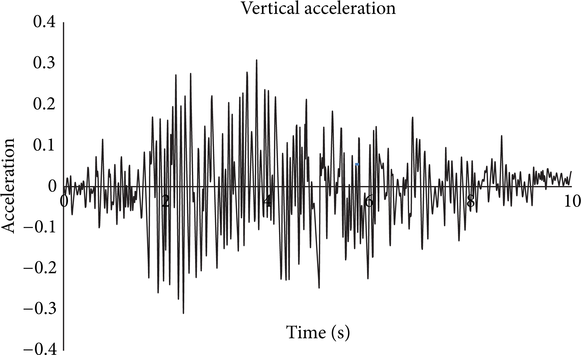
Vertical acceleration time histories of earthquake.
3. Modeling of Dam by ABAQUS Software
For modeling we need a proper case study to have a real simulated model. Karun-1 dam is created by noting its design sections. It is double curvature arch dam with 200 m height. Additional information is represented in Table 1 (see Figures 3 and 4).
Geometrical and material specification of Karun-1 dam.


View of Karun-1 dam.

Plan of Karun-1 dam.
To have compatibility between the geometry of the dam and the model, 8-node, 3-dimensional elements (C3D8RH) are used in ABAQUS.
4. Modeling of Abutments
Abutments modeling is done by considering the ratio of elasticity modulus of bed rock over elasticity modulus of dam body concrete (E r /E c ). The larger the ratio, the stiffer the bedrock, and it will result in low height for modeling of the abutments. It means that, with less bed rock stiffness, to have precise interaction between foundation and dam, we need more height to model the abutments. In this study the ratio is between 1 and 2. So, the dimensions of the abutments for modeling in any direction are considered equal to the dam height (U.S. Army, 1994).
Damping coefficient is calculated by Riley method. Damping coefficient can be obtained by means of linear combination of mass matrix and stiffness matrix. Coefficients of these linear components are calculated from frequency modes of dam:

α and β are Riley linear combining coefficients and calculated from (2) and (3):

In these equations ξ is the damping ratio and in dynamical analysis is assumed to be 5%. ω i and ω j are two angular frequencies of vibration modes. First five frequency modes that we extracted from model are represented in Table 2.
Five-mode frequency of dam.

In Karun-1 dam dynamic analysis Riley damping coefficients are calculated from first and third dam vibrating modes and critical damping ratio which was 5%: α = 0.1110 and β = 0.0210 [11].
5. Nonlinear Joint Model
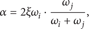
Concrete arch dams are constructed as individual cantilever blocks separated by vertical contraction joints. The contraction joints usually are grouted at the completion of the dam or in stages and may also include shear keys for additional resistance. However, contraction joints have limited tensile resistance and can open and close repeatedly during the earthquake ground shaking that produces net tensile forces across the joints. Such opening and closing of the joints are transient in nature but if severe can lead to unstable cantilever blocks and concrete crushing due to impact. The joint opening relieves tensile stresses across the joint but compressive stresses are increased due to the impact and reduced contact surfaces. This nonlinear behavior therefore needs to be investigated to ensure that the amount of joint opening and compressive stresses are not excessive. The contraction joint opening is modeled using a nonlinear joint element shown in Figure 5 [4]. The nonlinear joint element consists of two coincident surfaces, each defined by four nodes that may lie on a plane (See Figure 5(a)). The element stiffness properties, displacements, and stresses are computed at four Gauss integration points shown in Figure 5(b). The relative displacements between the two element surfaces (v) and produce stresses (q), according to the nonlinear relationship described in Figure 5(c). As shown in this figure, the element is characterized by the tensile strength, q0, and the stiffness, k. The tensile strength q0 can be selected to represent different joint types. For example, q0 = 0 represents an ungrouped joint or a grouted joint with zero tensile strength, whereas a nonzero q0 represents a grouted joint for which some tensile strength can be assumed. Finally, a large value of q0 may be used to simulate a linear analysis for which the joints are not permitted to open. The nonlinear joint elements are placed between cantilever blocks to model opening and closing of joints.
Nonlinear joint elements.
The dam model is developed using mesh generation capability of the ABAQUS program. It includes three layers of 8-node solid elements through the dam thickness (C3D8RH). The finite-element mesh of the dam is arranged along horizontal and vertical planes to model the joints. The vertical planes are oriented in the radial direction same as the contraction joints. This way, when needed, nonlinear joint elements can easily be inserted along the horizontal lift lines and the vertical contraction joints. Because of space limitations of paper, three studied points of dam are node 49 in up stream of dam at midpoint of crest level, node 43 on right side of crest level, and node 29 at midpoint of dam body (see Figure 6).

Finite-element meshes of dam body and studied points.
6. Computation of Nonlinear Earthquake Response
6.1. Dynamic Analysis and Extraction of Stress Time History
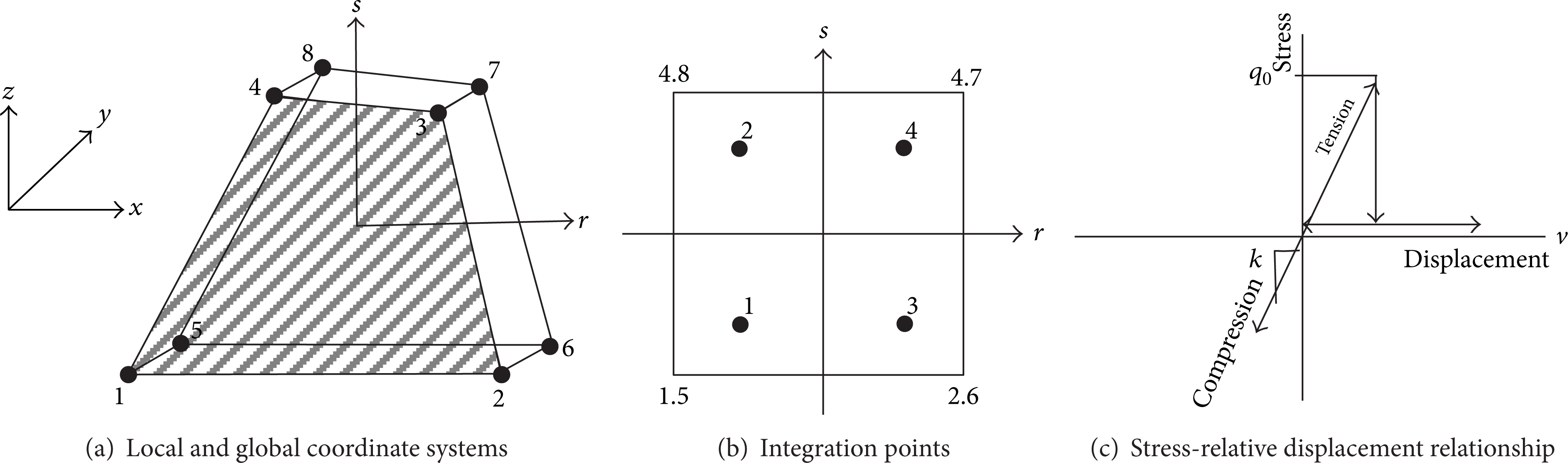
According to International Committee on Large Dams (ICOLD) for choosing the earthquake parameters, dam should withstand against applied credible earthquake. Some damages are allowed in limited areas for maximum design earthquake. These damages should be in a way that dam could keep impounded water. The analysis began with the applied of gravity and hydrostatic load and temperature loads as the initial conditions, followed by the step-by-step nonlinear time-history dynamic analysis for the dam with and without joints. Figure 7 shows envelope of maximum principal stress without joints and Figure 8 shows envelope of maximum principal stress with contraction and lift joints under dynamic analysis.
Envelope of maximum stress without joints.

Envelope of maximum stress with joints.
The figures show that stresses are reduced considerable in the model with joints. For both cases the maximum stress is near the abutments and minimum is at the midpoints of crest that are significant inclusion of joints. History graphs of stress at the studied points are represented in Figures 9, 10, and 11. The figures show that the effects of the joints are obvious, as stresses are considerably reduced in the model with joints for all of the studied points and they are almost zero. But in the model without joints the stresses are increased with high vibrations.

Stress history at midpoint of crest level (node 49) with and without joints.

Stress history at midpoint of dam body (node 29) with and without joints.
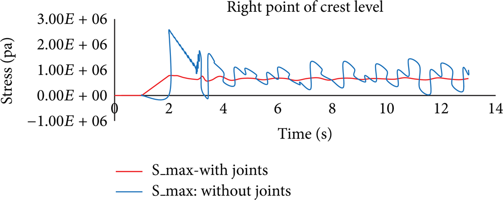
Stress history at right side of crest level (node 43) with and without joints.
6.2. Dynamic Analysis and Extraction of Displacement Time History
Results of dynamic analysis of the dam with and without joints are illustrated in Figures 12 and 13. In both models with and without joints, results show that displacement around abutment is near zero but maximum displacements happen in crest level especially at midpoint of crest. We see that displacements are distributed over the dam with maximum around crest. Displacements histories in reservoir direction (U2) at studied points are shown in Figures 14, 15, and 16. According to history graphs at node 43 in the dam with joints, displacements are increased with high vibration at midpoint of the dam (see Figure 16). The displacement history in the reservoir direction at node 29 and midpoint of crest (node 49) inclusion of joints is increased too (see Figures 14 and 15).

Envelope of displacement without joints.

Envelope of displacement with joints.

Displacement history at midpoint of crest (node 49) with and without joints.
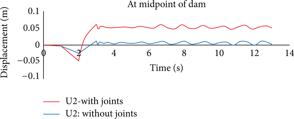
Displacement history at midpoint of dam body (node 29) with and without joints.
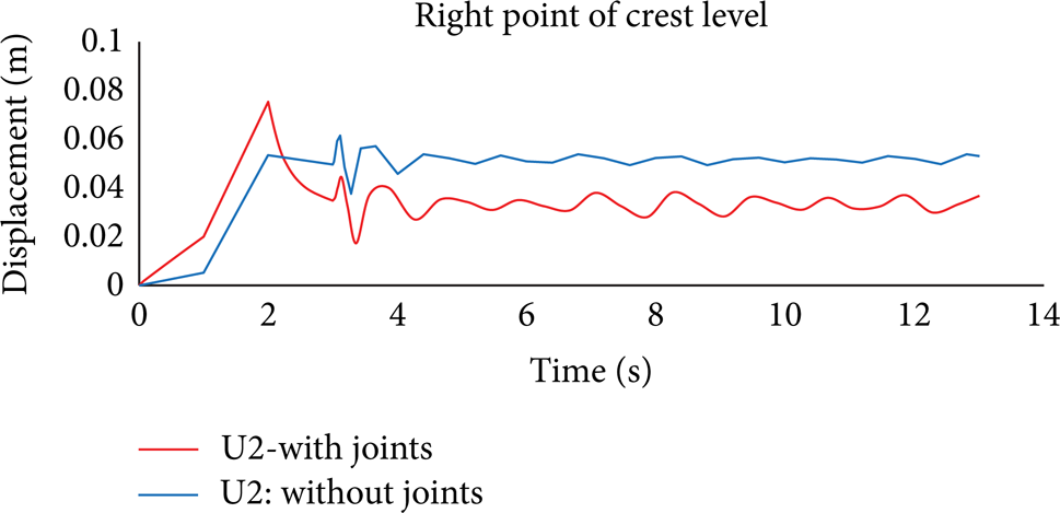
Displacement history at right side point of crest level (node 43) with and without joints.
7. Conclusions
According to the results of dynamic analysis and applied earthquake records, for both model of dam without joints and with contract and lift joints, maximum stresses occur around the abutments and maximum displacements are around the crest level especially at midpoint of the crest.
With inclusion of the contraction and lift joints, tensile stresses will be considerably reduced. Allowing joints slippage should further reduce tensile stresses, if such capability is available.
Inclusion of the contraction and lift joints will increase time history displacements especially at the right side point of the dam.
Identification of and stability analyses for isolated blocks that may get loose and overtop as a result of excessive joint opening and lift line cracking are necessary for assessing the overall safety of the dam and its ability to retain the impounded water.
Conflict of Interests
The authors declare that there is no conflict of interests regarding the publication of this paper.