
Abstract
A new dynamic cutting force model with nominal chip thickness is presented for predicting the stability of interrupted turning, in where the dynamical cutting force is defined by a function of nominal chip thickness and dynamical chip thickness. The stability lobes of interrupted turning are obtained based on full-discretization method and Floquet theory. Both numerical and experimental tests demonstrate that there is a strong correlation between the nominal chip thickness and the interrupted turning stability, and the proposed model is proved effective for the interrupted turning process.
1. Introduction
A machine tool directly influences the quality, productivity, and competitiveness of various production processes in the automotive industry and aerospace and die/mold industries. To maximize the productivity in a machining process, both the speed at which the tools can machine without causing deterioration in the stability of system and accurate evaluations of machining stability are crucial. In machining technology, chatter is a negative phenomenon that not only worsens the machined surface quality of the workpiece but also shortens the life of cutters. Since the late 1950s, regenerative chatter has been studied by several researchers [1–5]. The recent trend towards high speed and high precision cutting processes requires more accurate modeling of the cutting process for the purpose of predicting the conditions under which such chatter occurs.
It is well-known that cutting force characteristics have an important role in many aspects and especially in identifying chatter-free cutting conditions [6]. A comprehensive review of cutting force models has been presented by Ehmann et al. [7]. Armarego et al. proposed that the cutting force coefficients could be predicted from the average shear stress, shear angle, and friction coefficient by applying orthogonally to oblique transformation [8, 9]. The oblique transformation method is most useful when modeling solid tools with continuously varying edge and chip geometry [10]. A unified geometric, kinematic, and mechanic model was proposed which allows the prediction of chatter stability for multiple machining operations with defined cutting edges by Altintas et al. [11, 12]. A novel dynamic cutting force model is proposed by Li et al. [13], in which the cutting mechanism and the cutting force contribution on both the peripheral and the front cutting edges are taken into consideration simultaneously. An interrupted turning cutting force model was proposed and a detailed analysis of the stability was performed by Seguy et al. [14]. In the above studies [1–14], the cutting force models are linear, without considering nonlinearities in terms of chip thickness. Given this, power-law function for cutting force was used to analyse chatter by Hanna and Tobias [15] and Stépán et al. [16] and Yang et al. [17]. Recently, instead of approximating the cutting forces as a power-law function of the third-degree Taylor series (in terms of chip thickness), Moradi et al. proposed an extended nonlinear model of cutting force which is expressed as a completed third-order polynomial function of the chip thickness [18, 19]. As it is observed from Figure 1, according to the average values of deviation, polynomial cutting force model is in more correlation with the experimental data (rather than the linear and power-law model). Then dynamic cutting force models are obtained based on the different cutting force models to model governing equation of cutting process.

Cutting forces versus nominal chip thickness including linear model (red solid line) and power-law model (green solid line) and polynomial (blue solid line) model passing through experimental data [16].
It is worth noting that, in the above studies [1–19], dynamic cutting forces are only the function of dynamic chip thickness, and cutting force versus unit of dynamic chip thickness must be unique. However as shown in Figure 1, cutting forces versus the same dynamic chip thickness (Δh1 = Δh2) are unequal at different nominal chip thickness (ΔF1 ≠ ΔF2), due to the fact that the nominal chip thickness is neglected. In this paper, a dynamic cutting force model considering the nominal chip thickness is used to predict the stability of interrupted turning.
2. Basic Dynamic Interrupted Turning Model
In early linear model, cutting force is defined as

Then dynamic cutting force is

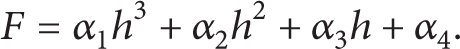
And in polynomial models of [16], cutting force is defined as
According to [16] the dynamic cutting force is

Neither (2) nor (4) can illuminate the phenomenon of that in the condition of Δh1 = Δh2 the cutting forces ΔF1 ≠ ΔF2 as shown in Figure 1.
Due to good agreement with experimental data, polynomial model for cutting force is adopted as
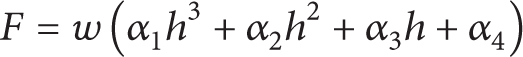
to model dynamic cutting force model, where h is chip thickness, w is chip width, and cutting force coefficients α i , i = 1,2, 3,4 are found directly from experimental force signals (as will be discussed through experiments). As shown in Figure 2, the linearization of expression (1) around the nominal chip thickness h0 yields


K0 is defined as a dynamic cutting force coefficient for h0. The chip thickness variation Δh can be expressed as the difference of the delayed tool edge position x(t − τ) and the present position x(t):

where the time delay τ is the time of one revolution of workpiece. Then dynamic cutting force is considered as

Dynamic cutting force characteristics.
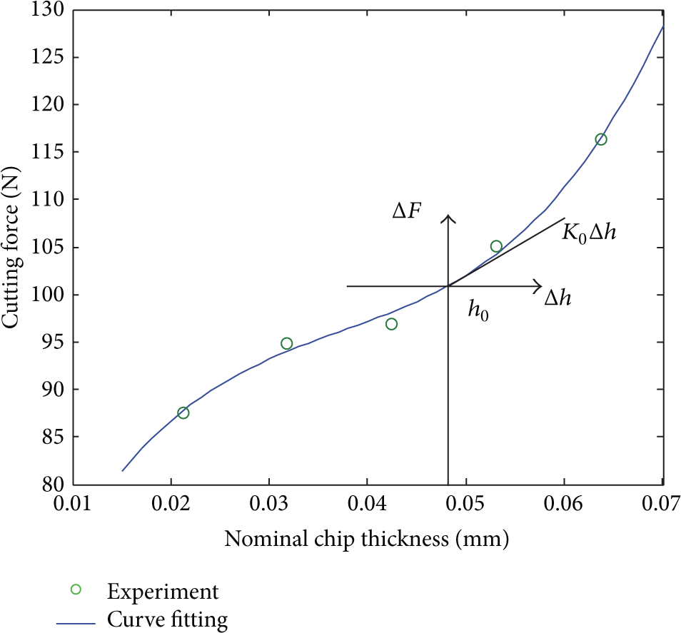
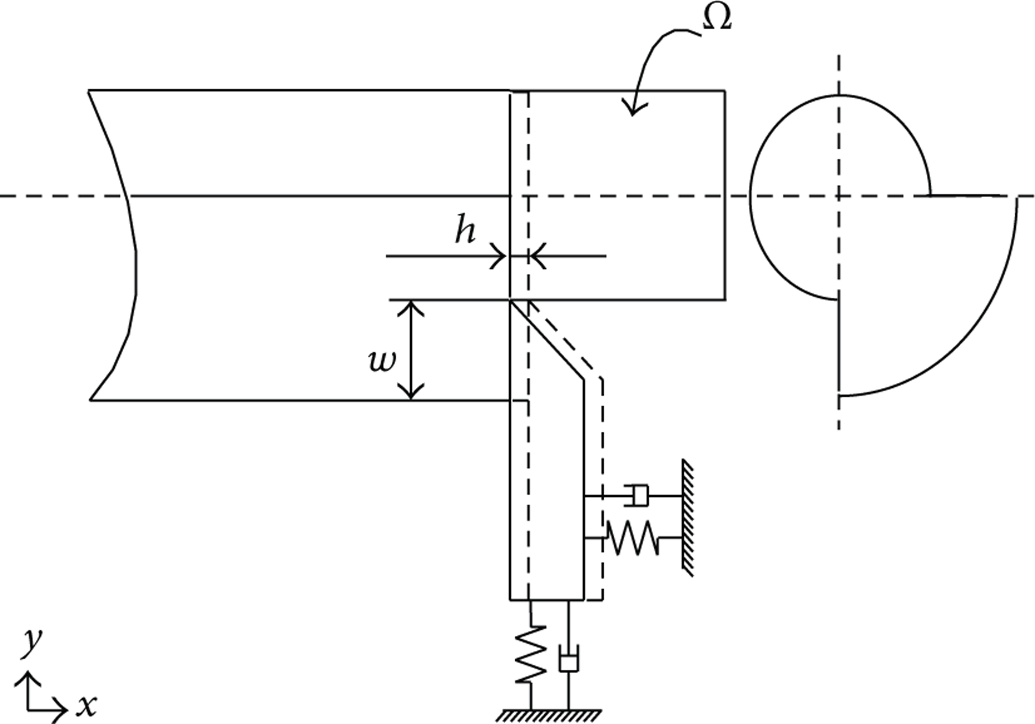
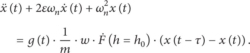
The dynamic model of the interrupted turning process employed here is shown in Figure 3, in which the tool is considered to be a spring-damper vibratory system. Because tool cutting edge angle is 90°, regeneration chatter mainly occurs in x direction. And then the governing equation of the interrupted turning system corresponds to

where ∊ is damping ratio, ω n is natural angular frequency (Hz), m is modal mass of the cutting tool (kg), g(t) is a window function determining whether the tool is in or out of cut, and ΔF is dynamic cutting force in terms of the state variable and time (N).
Schematic mechanical model of interrupted turning system.
Putting (9) into (10), the governing equation of the interrupted turning system is
3. Experimental Identification of Dynamic Parameters, Model Verification, and Discussion
3.1. Experimental Identification
To investigate the effectiveness of the methods described in Section 2, a series of experiment tests are performed on a CA6140 turning machine. The experimental setup is shown in Figure 4.

Experimental setup.
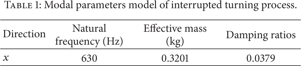
A carbide lathe tool with tool cutting edge angle of 90° was employed to cut steel 45#. For the experimental modal analysis, impact hammer of LMS was used to hit the tool in order to excite vibrations of the machine—tool structure. The Kistler 9257B was adopted to measure the cutting forces. Table 1 lists the modal parameters of the tool-machine structure, which were generated by the modal module of software LMS 10.0. Average values of F were calculated at different h0, as given in Table 2 and Figure 5 shows the plots of F − h0, while the best third-order polynomial function, passing through experimental data, was obtained via CFT of MATLAB. And the cutting force coefficients of (5) were calibrated as shown in Table 3.
Modal parameters model of interrupted turning process.
Average cutting forces F versus h0 (w = 0.5 mm).

Cutting force coefficients.


Average cutting forces F versus h0.
3.2. Model Verification
Based on the cutting force coefficients and tool modal parameters calibrated in the above section, as shown in Figures 6(a) and 6(b), stability lobes for the different h0 are predicted by using full-discretization method of [20]. Two sets of cutting tests with different nominal chip thicknesses h0 = 0.14 mm and h0 = 0.18 mm are carried out to investigate the effectiveness of the predicted lobes. From the cutting forces and their spectrum shown in Figure 6, it can be seen that chatter vibrations are severe and evident at red triangles experimental date points, and the blue squares experimental date points are stable. As shown in Figures 6(c) and 6(d), there is a good agreement between predicted lobes and experimental date. The method proposed in this paper is effective.

Predicted stability lobes, measured cutting forces, and their Fourier spectrum.
3.3. Discussion
It is well-known that when chip thickness h0 varies in a large range the cutting force exhibits nonlinearity. Polynomial function can approximate cutting force better than other different types of functions mentioned in this work which is helpful to model dynamic cutting force model for predicting cutting process stability. Stability lobes based on the dynamic cutting force model presented in this work have larger application range and more accuracy.
In Figures 6(a) and 6(b), the stability lobes, which correspond to different h0, are plotted together for comparisons. With h0 increasing, limit cutting width increases first and then changes to the trend of decrease, and maximum limit cutting width can be got at h0 = 0.14 mm. According to [1–20], limit cutting width depends on cutting force coefficients, and limit cutting width varies inversely as cutting force coefficients. From (7), it is can be known that cutting force coefficient K0 is the slope of curve shown in Figure 5. So, according to Figure 5, K0 decreases first and then changes to the trend of increase, which leads to the limit cutting width that increases first and then changes to the trend of decrease.
When the cutting processing parameters are elected according to the predicted lobe, chip thickness corresponding to minimum slope should be elected as nominal chip thickness, and then choose appropriate cutting width and spindle speed, which is helpful to improve machining efficiency and ensure the cutting process stable.
4. Conclusion
In this paper, a new dynamic cutting force model is proposed. In this model, nominal chip thickness and dynamical chip thickness are included. Modal experiments and measurement of cutting forces (at various nominal chip thicknesses) are performed to determine the modal parameters and coefficients of the cutting force model. After construction of stability lobes diagram via full-discretization method and using the experimental data to demonstrate their effectiveness, we know that stability boundary changes with variation of nominal chip thickness. So it is obvious that the nominal chip thickness has great influence on the stability of interrupted turning process and the new dynamic cutting force model in this paper can explain how the nominal chip thickness affects the stability of cutting process.
Conflict of Interests
The authors declare that there is no conflict of interests regarding the publication of this paper.
Footnotes
Acknowledgment
This research was financially supported by the National Natural Science Foundation of China (Grant no. 51275347).