
Abstract
The large eddy simulation (LES) method based on Vreman subgrid-scale model and SIMPIEC algorithm were applied to accurately capture the flowing character in Francis turbine passage under the small opening condition. The methodology proposed is effective to understand the flow structure well. It overcomes the limitation of eddy-viscosity model which is excessive, dissipative. Distributions of pressure, velocity, and vorticity as well as some special flow structure in guide vane near-wall zones and blade passage were gained. The results show that the tangential velocity component of fluid has absolute superiority under small opening condition. This situation aggravates the impact between the wake vortices that shed from guide vanes. The critical influence on the balance of unit by spiral vortex in blade passage and the nonuniform flow around guide vane, combined with the transmitting of stress wave, has been confirmed.
1. Introduction
The rotating turbulent flow in hydraulic machinery contains quite complicated multiscale helicity turbulence structures due to the driven rotating and interacting between viscous fluid and impeller structure. One of the things that make rotating turbulent flow in hydro-turbine different than channel flow is the complexity of flow passage, which results in multiscale helicity turbulence structures and multiscale effect. All these above aggravate the complexity of rotation turbulent. Hydraulic factor caused by rotating turbulent flow is one of the most important parameters which can induce unit vibration, Due to diversity and complexity of rotating turbulent flow inside a hydraulic machinery, the development physics of the overscale structures in the rotating turbulent flow is not fully clear even now. The vibration amplitude induced by rotating turbulent flow is large, and usually all of the unit is difficult to avoid. Especially, in some case that deviation from the optimal working conditions, such as small open flow condition and transient process condition. The swirl, flow separation, and backflow in flow passage would become more obvious and complicated, which easily induce the abnormal vibration or fatigue damaged occurred in structure with vibration frequency more multifarious, for instance, in Francis turbine of Gong-Zui project, Shi-Quan project, Liu-Jia-Xia project, Li-Jia-Xia project, and so forth. The pressure pulsation amplitude in the draft tube under small open flow condition is larger. Its frequency is also larger than unit rotation frequency, even multitimes of the unit rotation frequency [1].
As for Gong-Zui project after 20-year operation, turbine loses efficiency severely, crack occurred on the connection between runner crown and blade exit, front face of blade was damaged severely by sediment, and the cavitation is found on the back face of blade. Due to the damage of turbine, Canada company GE Hydro is committed to improve two turbines for more capacity. After improvement, obvious vibration and large noise were found in some condition. In this situation, many theoretical analyses, model tests, and field tests were done. The results show that high vibration and large noise are induced by interblade vortices under the no-load or low load condition, which can be avoided by means of air admission [1]. From June 2003 to August 2003, several overspeed 140% tests were done for No. 5 and No. 6 unit of Three Gorges left bank hydropower station; all the tests have abnormal vibration when guide vane is closed to 4% and vibration frequency is the same as low frequency pressure pulsation in guide vane, spiral case, and vanes surface. So the vibration is due to resonance between fluid and structure [2–4]. The solution may extend the shut-down time of servomotor third part. According to the analysis and testing by Ziqin et al. [5], the shut-down time should not be less than 40's, and start point should be increased from 6.4% to 8%, which can avoid abnormal vibration when there is overspeed shutdown.
As for most of power stations, it is very difficult to locate the reason of hydro-unstability. It is not fully clear for the mechanism of induced vibration. Although sometimes some method can temporarily solve the problem, like the above method: compensate air, newly designed blade, and load control and avoid the critical loading condition. They cannot permanently solve the problem. Although turbine mainly uses runner for power transformation, runner is not an individual part, which is affected by spiral case, water guide domain, and draft tube. Unless through accurately predicting turbulence evolution characteristic in whole passage, like flow speed, pressure pulsation distribution rules, and capture of subgrid-scale vorticity, and so forth, it is difficult to fully accurately understand the mechanism of fluid inducing structure vibration and provide guidance for vibration testing and diagnosing. Therefore, fully understanding flow field characteristic is very important for hydro-stability and solving problems.
However, the rotating turbulent flow simulation under small opening condition has not yet been presented in publications. Hence, this paper attempts (i) to investigate the turbulence features by using LES method and (ii) to understand the effects of interblade vortices on the crack of blade when the spiral vortex, flow separation, and backflow dominate the flow flied.
2. SGS Model and Numerical Model
The governing equations in LES are obtained by filtering the original Navier-Stokes equations. The filtered expressions of a Newtonian incompressible fluid are given as follows:

where

In (1), the L ij and C ij are Leonard and crossed terms, respectively, L ij represents the interaction between large scales turbulence, and C ij is large scales and subgrid-scales turbulence. While R ij is Reynolds subgrid tensor represents components of the subgrid-scales. The subgrid stresses are unknown and require modeling. The Eddy-viscosity model (also called Smagorinsky-Lilly model) [6] is frequently used to represent the effects of SGS in LES, since they are robust in practice and principally respect the dissipative character of turbulence.
But it is well known that the Eddy-viscosity model has the most serious shortcoming in predicted complex turbulence, such as the fact that it causes excessive damping of large-scale fluctuations in the presence of mean shear and in transitional flows near solid boundaries [8]. In short, Smagorinsky's constant is not a universal constant, which is serious shortcoming of this simple model. The development of subgrid models for large-eddy simulation (LES) is an important area in turbulence research. Vreman [9] conceived a new eddy-viscosity model to overcome the limitation of Smagorinsky-Lilly model and applied it in large-eddy simulation of turbulent shear flows with quite satisfactory results. The model is essentially not more complicate than the Smagorinsky-Lilly model but is constructed in such a way that its dissipation is relatively small in transitional and near-wall regions. The model is expressed in first-order derivatives, does not involve explicit filtering, averaging, or clipping procedures, and is rotationally invariant for isotropic filter widths. Because of these highly desirable properties the model seems to be well suited for engineering applications. In this study, the Vreman model was applied to yield the best results for a rotating turbulent flow under small opening condition of Francis turbine. The Vreman model can be expressed as follows:
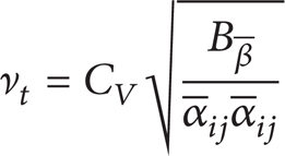
with
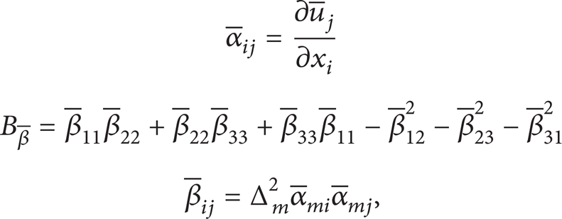
where C
V
is model constant and is related to Smagorinsky's constant C
S
by C
V
≈ 2.5C
S
2 for isotropic turbulence. Δ
m
is grid filter width (m = x,y,z). α is the (3 × 3) matrix of derivatives of the filtered velocity
Based on the idea of subgrid dissipation and viscous dissipation integral balance, the transport equation of τ ii under Vreman model can been given as

By volume average above equation, the entire equilibrium equations are obtained as

Using (6) and scale similarity relation

where
An implicit finite-volume method is used for solving the incompressible N-S equations. The viscous subgrid fluxes are approximated by differences of second-order accuracy and the convective term is discretized using the scheme of second-order upwind. The pressure-velocity coupling is realized with the SIMPLEC algorithm. The details on the numerical method can be found in [15].
The computational domain, some details of turbine mesh model, and the main parameters are shown in Figure 1 and Table 1. The computational domain is full passage of type HLA551-LJ-43 Francis turbine, including the spiral case, stay vanes, guide vanes, blades, and the draft tube. The diameter of runner is 430 mm. The rated speed and the attack angle of guide vane are 600 r/min and 9.5°, respectively. The mesh is approximately 27.4 millions. According to the spiral case inlet velocity and the hydraulic diameter the Reynolds number is 180 thousand.
Main parameters of turbine.

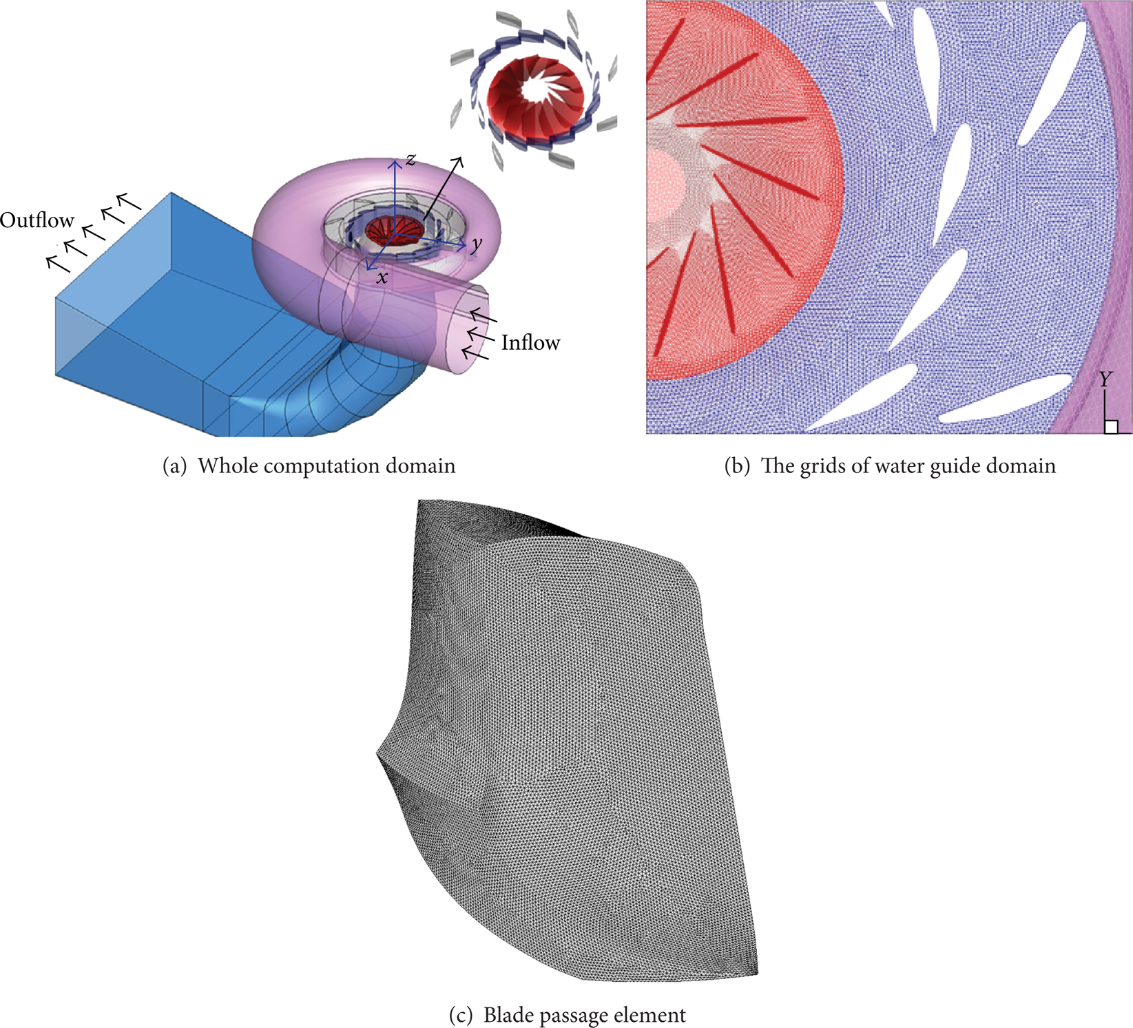
Whole computational domain for turbine and blade passage element.
3. Results and Discussions
3.1. Turbulence Characteristics in Gate Operating Mechanism
Figures 2 and 3 show the velocity and vorticity contours, respectively, in the turbine flow passage. As is shown in the Figures, the velocity and vorticity are uniform with the fact that the fluid flows before guide vanes. In Figure 2, the velocity gradient changes sharply near the inlet of runner blades passage and the total velocity of the fluid is bigger especially at slipping interface, when the fluid flows out from guide vane. It also can be seen from Figure 3 that the fluid flows tempestuously after flowing out guide vanes. There are different scales of vortex structure. With the water flowing downstream, the concentrated vortexes shed from guide vanes interfere with each other and separate. Consequently, they flow into runner blades and collide with blades, forming almost identical scale of vortexes at inlet of the runner blades, further increasing the vortex intensity, because of the influence of runner dynamic and static interference. The vortex structure is relatively symmetric in interblade passage with low vortex intensity.

The velocity distributions at t/T = 6.0 time (Unit: m·s−1).

Instantaneous spanwise vorticity distributions at t/T = 6.0 time (Unit: s−1).
According to the vorticity distribution from outlet of guide vanes to inlet of runner, (1) under small opening conditions, the flow path is lengthened, which strengthen the interaction effect of wake vortex of adjacent vanes resulting in complex fluid motion; (2) the fluid flows into runner with dominant tangential velocity component after flowing out from guide vanes. In the process, wake vortexes impact each other and exchange their energy and further separate and evolve into new and complex vortex structure; the distribution range of vortex scale becomes wide; (3) due to the interference among the vortexes, it is hard to find regular Karman-vortex from the Figure, while the prototype of irregular Karman vortex after evolution still can be seen from Figure 3(a).
Figure 4 shows the streamline distribution around guide vane for some time. It can be seen from the Figure that (1) the fluid flow is extremely uneven along the guide vane height direction. The fluid on the lower portion of guide vane climbs upwards with spiral-shape after impacting guide vanes and flows out from the middle of the guide vane. Therefore, backflow formed at the entrance of the bottom ring section to block the fluid to flow, as shown in Figures 4(a) and 4(b); (2) from the streamline distribution on the surface of guide vane, the following characteristics can be more clearly seen: at the front of guide blade, there is an obvious local flow separation point (see Figure 4(c)) and a stagnation point and high pressure region is formed here, while a large low pressure region is formed in the middle of guide vane because of confluence (see Figure 5(a)). The pressure on the surface of guide vane is lower than that of back of guide vane for the above reason; (3) the fluid on the back of guide vane is uniform. Just near the bottom ring, a local high pressure gradient is formed because it was affected by high pressure region between adjacent vanes, as shown in Figure 5(b).

The streamline of guide vane surface and its near-wall zones at t/T = 6.0 time.
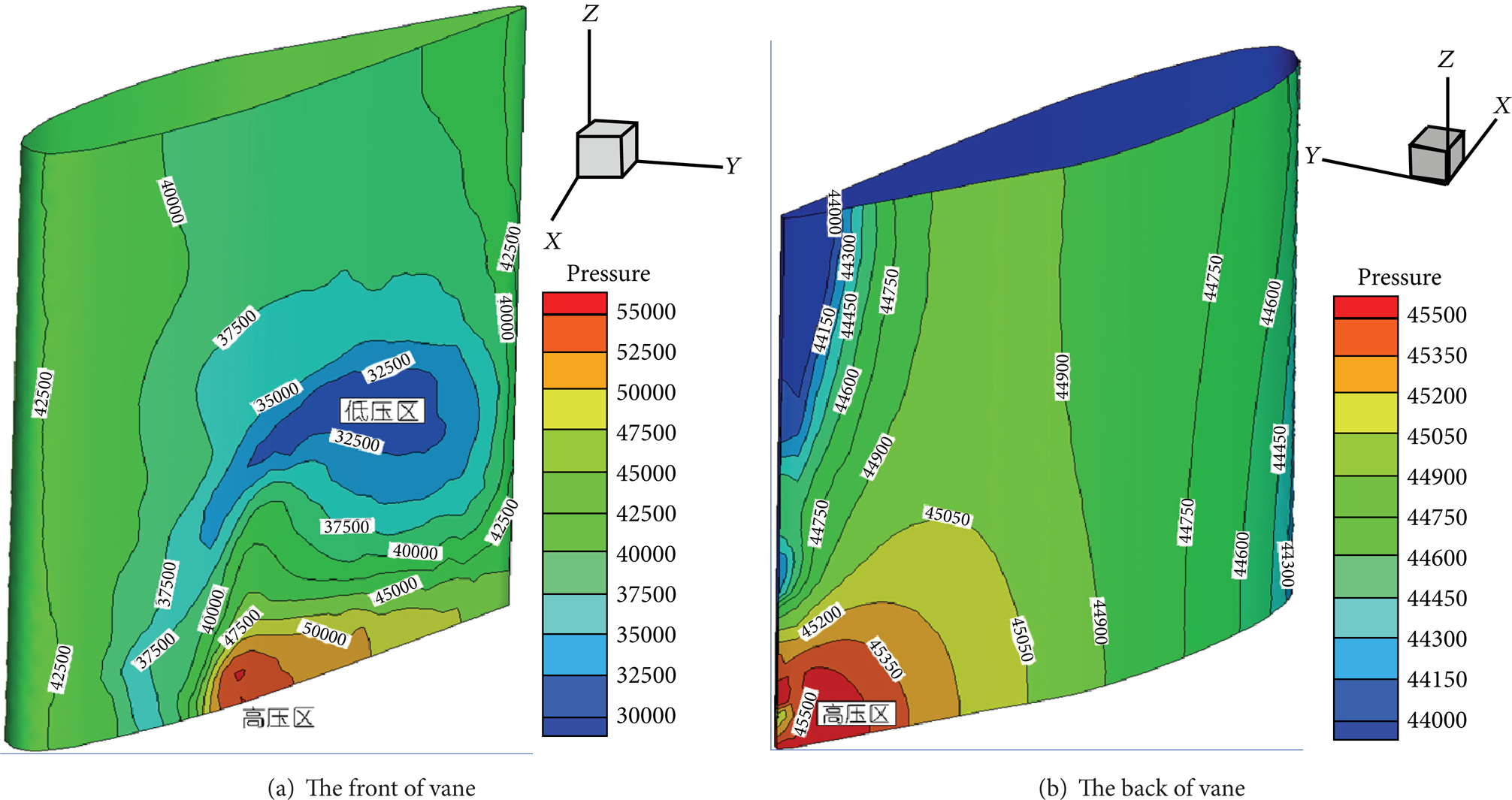
The pressure distributions of guide vane surface at t/T = 6.0 time (Unit: Pa).
3.2. Vortex Structure in Runner Blade Passage
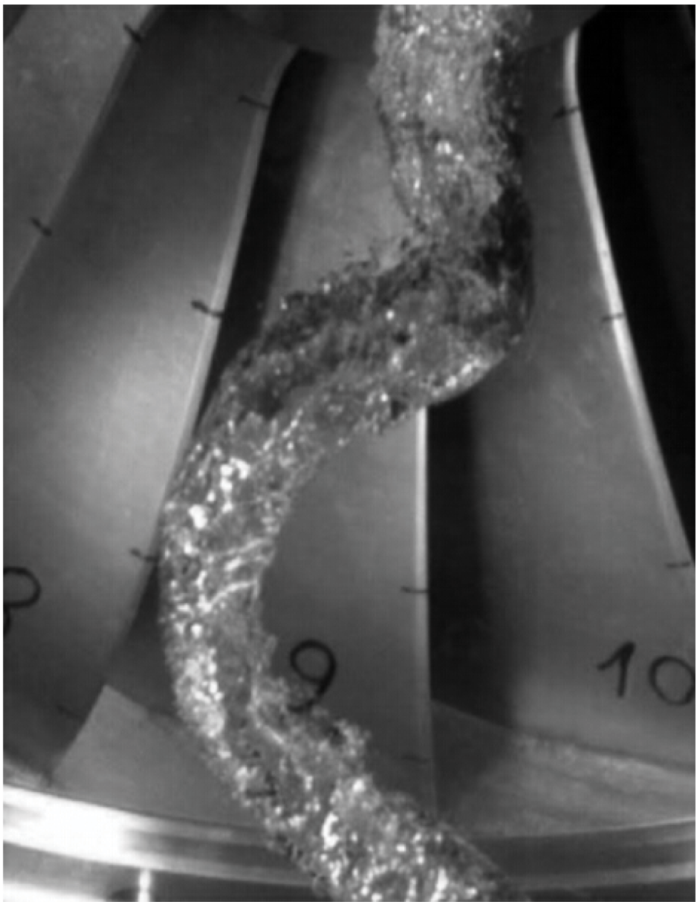
Figure 6 shows the pressure contours in turbine flow passage. The pressure along runner radial is gradually reduced. Near the outlet of the runner crown, there are low pressure regions whose sizes almost are equal. They are places which produce interblade vortex (a centralized spiral-shaped vortex). Since the nonimpact condition is no longer satisfied at runner inlet, there is an attack angle when turbine operates away from the optimal condition, such as small guide vane opening condition. It causes water to separate from blades or crown inlet; the separated vortexes enter into runner and form interblade vortex which emerging an obvious low pressure region on the surface of runner blades. There are high pressure regions which occurred on the connection between runner crown and the outlet of blades which are far away from interblade vortex, as shown in Figure 7. That is why the blades crack initiated almost at these high-risk regions in practical projects (see Figure 8).
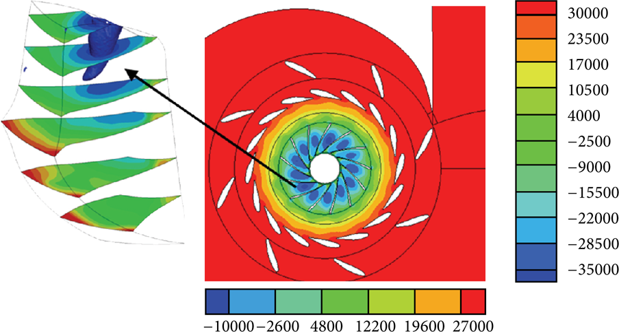
The means pressure in blade passage (Unit: Pa).

The wall press of blade (Unit: Pa).

Typical cracks on blade.
It can be clearly seen from Figure 9(a) (vorticity structure along the spanwise) the interblade vortex are nonuniform and unsteady to evolve in space and time. They are with large eddy scale and high energy flowing along negative pressure region to downstream and losing its structure stability gradually. These vortices bifurcate, continuously evolve many small scale vortices to fill with downstream of blades passages. The flow in upstream is stable, the flow near blade outlet is rapidly changed, and the flow state is upheaval and easy to induce blades to vibrate unsteadily. The vortex structure in the fluid regions that are not occupied by spiral vortices is kept stable and this part of fluid is relatively ideal (see Figure 9(b)).

Instantaneous isosurface of spanwise vorticity in blade passage at t/T = 6.0 time (Unit: s−1).
3.3. Fluid Structure in Draft Tube
When fluid flows forward freely in draft tube with movement condition of tangential velocity component being dominant, it will produce separation and backflow at the center of vortex because of the influence of pressure in the draft tube, which may form low pressure or vacuum cavity due to cavitation. Consequently, a tangible vortex band is formed (shown in Figure 10) and the fluid flows around the cavity zone with spiral-shaped vortex. This paper has captured turbulence characteristics near-wall area with high intensity and unique phenomenon of separation for the above reason. But low pressure zone is bigger and irregular and the fluid also presents reflux with upward trend in curved section, where the regular physical eddy to wiggle around draft tube axis cannot be found. Because it is different from conventional vortex band form, so in this paper, we call it “Cavity vortex band,” as shown in Figure 11. The authors think that the tangential velocity component of fluid is absolute advantage under the conditions of small opening. It can be seen from Figure 12 that the fluid velocity within the range of 0∼0.7 R is significantly lower than the range of 0.7∼1 R. Therefore, the circumferential turbulence intensity is enhanced in near-wall area showing obvious rotating turbulence form (shown in Figure 13), which leads to the fluid being thrown along wall after entering draft tube presenting a trend of rotational movement. As seen in Figure 14, fluid not only separates obviously in cone section and curved section of draft tube, but also directly led to huge cavity vortex band to form in the center of draft tube. This region belongs to low pressure zone with bigger off-center, which directly collides against wall of draft tube. It is easy to induce low frequency vibration.
Typical vortex rope in draft tube of hydraulic turbine.

The isosurface of RMS pressure (0.4 kPa).

Distributions of tangential velocity along the radius at draft tube inlet (Unit: m1/2·s−1) [7].

Instantaneous isosurface of spanwise vorticity at t/T = 6.0 time (Wz = 90 s−1).

The streamline of draft tube.
Special fluid structure exists in draft tube under small opening conditions comparing with conventional conditions (Figure 14).
The fluid flows unevenly in radial direction in conical section and bend section. The turbulent intensity near wall is showing obviously as rotating turbulent flow.
The obvious separation and backflows in conical section and bend section are produced since tangential velocity component is dominant. Fluid flow is approximately divided into three parts. (1) Most of the fluid flows downward along wall with spiral shape. After reaching diverging section, the fluid diffuses gradually and then flows downwards uniformly; (2) a big cavity (vortex band) is formed by the part of fluid in the middle of draft tube; it belongs to low pressure region and the pressure on the edge of cavity is 0.4 kPa; (3) When the main current which flows downward along wall reaches diverging section, it begins to bifurcate as affected by low pressure zone of vortex band; only small part of fluid flows back.
Backflow region produced in draft tube may be divided into two parts. One exists at inlet of diverging section and another is the flow state that the fluid presents upward backflow and then is rushed downward when part of fluid flowing spirally around low pressure zone reaches bend section.
3.4. Pressure Characteristic on Wall
Figures 15, 16, and 17 are the time-history and FFT (Fast Fourier Transform) graphs of pressure pulsation about spiral case, guide vanes, and runner blades, respectively. In each graph, the time-history figure is on the left and the FFT graph is on the right. Under small opening condition (n = 600 r/min; the guide vane opening is 20%), fluctuating pressure amplitude and its corresponding main frequencies about each monitoring point are listed in Table 2. The following can be seen from these charts.
The amplitude and frequency of monitoring point.


The evolution of pressure and its Fast Fourier Transform (FFT) in spiral case.

The evolution of pressure and its Fast Fourier Transform (FFT) in guide vane.

The evolution of pressure and its Fast Fourier Transform (FFT) in blade.
4. Conclusions
The method of large eddy simulation (LES) base on Vreman Subgrid-scale model is applied to analyze the generation and evolution process of turbulence flow and capture the details of the flow structures and the dissipation of the turbulent kinetic energy. The SIMPIEC algorithm is used to solve the coupled equation of velocity and pressure. The result shows that the small guide opening conditions are the most deviated one from the optimal working conditions and the tangential velocity component of fluid is dominant. The special flow structure has been induced consequently, such as rotating turbulent flow in gate operating mechanism, the nonuniform flow around guide, the spiral vortex in blade passage, and the flow separation and backflow in draft tube. It can be deduced that the abnormal vibration of unit is induced by those unstable flow characters combined with the transmitting of stress wave, and the transmitting of low frequency pressure wave in the whole flow passage is the main factor influencing turbine and fluid to resonant.
Conflict of Interests
The authors declare that there is no conflict of interests regarding the publication of this paper.
Footnotes
Acknowledgments
This work was financially supported by National Natural Science Foundation of China (NSFC) (Grant nos. 51309128 and 51279071), the Specialized Research Fund for the Doctoral Program of Higher Education (no. 20135314130002), and the Fok Ying Tung Education Foundation (no. 141120).