
Abstract
Circular diamond saws rotating in high speed are widely used to cut hard materials, and narrow slots on saw blades are sometimes used to reduce the blades' vibration and noise. Sizing optimization of the internal, annular slots on saw blades is investigated in this paper. First, an accurate finite element model representing an actual saw blade is obtained by model updating. Then, sizing optimization on two types of annular slots is performed to maximize the frequency separation between the finite element analysis results and the saw blade's operational speed and to reduce the possibility of structural resonance. Optimization results demonstrate great improvements in frequency separation from the rotating speed of 500 Hz for the optimized models, and stress analyses on the optimized blade models confirm the structural integrity of the designs.
1. Introduction
Working in high speed, circular diamond saws are widely used to cut, dice, or groove hard materials such as ceramics, optical glasses, rock, metal, and electronic materials. The advantage of using diamond saws is that they can cut high aspect ratio work-pieces very efficiently. In the electronics industry, the machining speed of diamond saws for cutting Si wafers of thickness 200 μm can be more than three times as fast as that of UV lasers [1]. In particular, to cut wafers with thickness in millimeters, abrasive diamond saws are the only logical choice. The main body of a circular diamond saw blade is usually made of carbon steel or manganese steel, for example, 65 Mn steel. The blade tip is slightly thicker than the blade body and diamond grits of sizes in micrometers are adhered to the blade tip by the cataphoresis process. Some diamond saw blades have radial or/and internal, annular slots symmetrically distributed about the center hole. These narrow slots are used to increase the thermal dispersion efficiency of the blade and to reduce vibration and noise when the blade rotates in high speed. Figure 1(a) shows a common circular diamond saw blade, and Figure 1(b) demonstrates a saw blade mounted on a sawing machine by clamping the blade with two flanges during a cutting operation.
(a) Circular diamond saw blade and (b) clamping of the blade in a sawing machine.
A saw blade in operation can produce a high level of noise and even cause severe noise pollution in the work place. When the rotation speed is at or near one of the natural frequencies of the blade, resonance occurs and vibration and noise levels increase dramatically. Although they may weaken the blade structure, slots on a blade can decrease the vibration and noise intensity. Singh [2], through experimentation, observed the effects of radial slots on idling blades and found that radial openings destroyed the continuity of vibrational mode shapes of the blades, and sound wave transmission was also obstructed due to geometrical discontinuity. As a result, both vibration and noise levels were significantly diminished. Hattori and Iida [3] experimented on blades made of high-damping alloy and successfully suppressed the level of whistling noise. Chen and Chang [4] proposed a two-stepped procedure for the optimum design of circular diamond saw blades, in an attempt to reduce the possibility of structural resonance. In step one, an accurate finite element (FE) model representing an actual saw blade is acquired by incorporating experimental and finite element analysis (FEA) frequencies to update the blade FE model. In step two, shape optimization of the radial slots on the blade, based on the updated geometrical parameters obtained in step one, is performed to maximize the frequency separation between the FEA results and the saw's operational speed. Other research works about circular saw blades include the following: Ishihara et al. [5] studied the dynamic behavior of thermally loaded circular disks based on plate bending theories and Schajer and Steinzig [6] employed electronic speckle pattern interferometry (ESPI) to measure the natural frequencies and mode shapes of saw blades.
To investigate the dynamic behavior of a diamond saw blade, both experimental techniques and the finite element method (FEM) may be employed. Applying FEM to analyze a structure requires the geometrical and material properties of the structure as input parameters. A small error in one input parameter can produce large deviations from the true structural responses. In order to obtain a more accurate and reliable finite element model of a structure, the FE model updating (or tuning) has been an active research area [7–10]. The FE model updating procedure utilizes measured and FEA natural frequencies that were paired together according to their mode shapes, and it incorporates an optimization sequence that formulates the frequency differences as an error vector for minimization. The updated FE model is considered to be a better model for future dynamic response predictions or design modifications. Arora et al. [11] proposed a two stage updating procedure, in which the mass and stiffness matrices are first updated and then the damping matrix whose effects are normally excluded in the updating process. When applying the model updating procedure, a better result may be obtained if the resolution (degrees of freedom) of the experimentally measured data can be enhanced. Wang et al. [12] utilized a high-speed digital camera and an image processing technique to acquire a massive amount of full-field mode shape data for model updating. The updating concept can also be applied to other areas. Fang and Perera [13] applied the tuning technique to structural damage detection problems. In a tutorial presentation, Mottershead et al. [14] discussed several simple examples and a large scale example of a helicopter airframe using a sensitivity-based updating procedure.
This research creates an accurate finite element model representing an actual saw blade by FE model updating and investigates the sizing optimization of several types of the annular slots with the frequency separation between the FEA results and the saw's operational speed as the objective function to be maximized. The sizing optimization of the annular slots is performed on finite element models that are derived from an experimentally updated model. The optimization results should provide improved designs for saw blades that produce minimal vibration and noise during operation. The finite element analysis and the sizing optimization are carried out by the use of the commercial software ANSYS and the ANSYS parametric design language (APDL) with the first order optimization scheme.
2. Research Methods
2.1. Experimental Modal Testing
A circular diamond saw blade with a center-hole diameter of 22 mm, an outer diameter of 230 mm, and 16 radial slots was tested to extract its natural frequencies and mode shapes in a modal testing experiment. In the test setup, the blade was suspended by two thin strings to simulate a free-free boundary condition, and a miniature instrumented impact hammer and a miniature accelerometer were used to provide input force and measure response signal. Figure 2 shows the blade structure in a modal testing experiment setup. Figure 3(a) shows the blade's test grid, and the accelerometer was fixed at grid point number 193. The impact hammer strokes each grid point three times and the frequency response functions were averaged. The test results including the test frequencies, damping coefficients, and the mode shapes are shown in Figure 4.

The saw blade structure under study in a modal test setup.
(a) Test grid and finite element grid of the saw blade (b) in a free-free boundary condition and (c) in a fixed boundary condition.

The test frequencies, damping coefficients, and the mode shapes of the saw blade.
2.2. Finite Element Analysis
The blade body and tip are measured to have thicknesses of roughly 2 mm and 2.6 mm, respectively. Also, the blade is measured at 531 grams. Finite element models for the blade in two different boundary conditions (BC) are created using the ANSYS software with SHELL93 elements: a free-free BC (Figure 3(b)) and a fixed BC (Figure 3(c)). The model with the free-free BC will be used later for model updating, and the one with the fixed BC simulating a saw blade clamped by two flanges on a sawing machine (Figure 1(b)) will be modified to investigate the effects of annular slots. Figure 5 displays the FEA frequencies and mode shapes of the first model, in which Mode (0, 2), for example, symbolizes a mode with 0 nodal circle line and 2 nodal diameter lines. Note that due to structural symmetry most modes will appear in pairs (orthogonal pairs) but only one mode from each pair of the symmetrical modes is shown. Comparing the test and the FEA results in Figures 4 and 5 reveals that although each two corresponding frequencies disagree quite significantly, their mode shapes match rather well. Further, when a saw blade revolves, rotation stiffening effects will take place. The faster the blade rotates, the higher the frequencies increase. Finite element analysis of a saw blade rotating in high speed must take account of the stiffening effects.

FEA frequencies and mode shapes of the initial model.
2.3. Model Updating
Usually combined with an optimization technique, an FE model updating procedure modifies the FE model and seeks to minimize the difference between the analysis and the experimental results. The model updating process begins with experimental measurements of the natural frequencies and mode shapes of the structure tested. The FE model of the structure is created and then analyzed. Since the values of the finite element input parameters are often not precise, it is very likely that the measured and the predicted results will show a significant discrepancy. By carefully comparing the experimental and FEA mode shapes, matching modes are correctly paired, which is important since the order of the FEA modal data can be different from that of the measured data. By defining the error vector as a vector containing the relative differences between the experimental and FEA natural frequencies, an optimization problem can be formulated as to minimize the length of the error vector:

where fi is the natural frequency for the matched mode i; the superscripts a and e represent FEA and experimental results, respectively; m T represents the total mass of the blade model, M the measured mass, and ε a small positive value; xj is the jth FE input parameter and XjL and XjU denote its lower and upper bounds, respectively; m is the number of modes included in the optimization process; and n is the number of FE input parameters to be updated. This optimization problem is solved to yield a set of updated parameters, and then the results are checked for convergence. If converged, the process can be stopped; otherwise, FEA is once again performed using the updated parameters to produce a new set of modal data leading to the next iteration, and the procedure is continued in an iterative way.
Since the blade tips are embedded with diamond grids, they have very rough surfaces. And the blade body is usually coated with a thick layer of paint, which makes the exact thickness of the blade body difficult to determine. Therefore, in this study, the tip thickness, denoted as x1, and the blade thickness, x2, are set as the updating parameters. In addition, to reduce the risk of introducing further modeling errors while applying boundary conditions, the modal testing experiment of the blade was conducted under a free-free boundary condition and so is the finite element model constructed.
2.4. Sizing Optimization
After the FE model is updated, the sizes of the internal, annular slots on a saw blade can be optimized by maximizing the frequency differences between the blade's natural frequencies and the saw's operational speed. The shape optimization problem is formulated as follows:

where ω is the saw's operational rotation speed; xj in this step represents the sizing parameters of the radial slots; and r and s represent the number of frequencies and design parameters included in the optimization process, respectively. To maximize the objective function defined in (2) is to enforce the blade's natural frequencies to separate from the saw's operational speed as far as possible. Therefore, the possibility of structural resonance can be minimized.
Two types of annular slots are examined in this paper. Figure 6(a) displays the 3 parameters (r, θ, and w) defining a Type A slot, while Figure 6(b) exhibits the 4 parameters (r1, r2, θ, and w) for a Type B slot. Figure 7(a) demonstrates saw blades with 3, 4, 5, and 6 Type A slots, and Figure 7(b) shows a saw blade with 4 Type B slots. Blades shown in Figure 7(a) can be used to study the effects of the number of openings on the dynamic characteristics of a blade. The saw blades mounted on a sawing machine are simulated by a fixed boundary condition as shown in Figure 3(c).
Design parameters for (a) Type A slots and (b) Type B slots.

(a) Saw blades with 3, 4, 5, and 6 Type A slots and (b) saw blade with 4 Type B slots.
3. Results and Discussion
3.1. The Updated Model
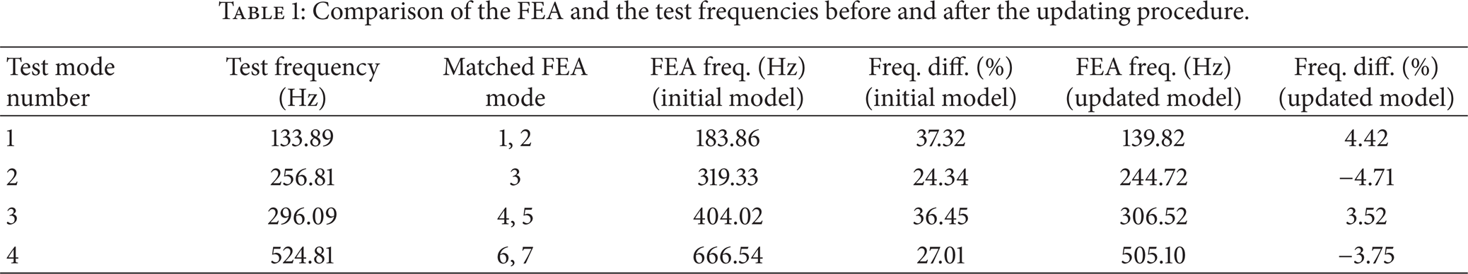
Applying the updating scheme with m = 4, M = 531 grams, ε = 2 grams, and n = 2 (x1: tip thickness and x2: blade thickness), the updating process converged in 30 iterations. The final updated tip and blade thicknesses are 1.57 mm and 0.97 mm, respectively. A comparison of the FEA and the test frequencies together with their differences before and after the updating procedure are given in Table 1. There are significant discrepancies between the test and the initial model's FEA frequencies. The updating technique reduces the disagreements dramatically, with the largest difference from more than 37% before updating to less than 5% after.
Comparison of the FEA and the test frequencies before and after the updating procedure.
3.2. Sizing Optimization for Type A Slots
Type A slots have 3 design variables (s = 3), there are 2 frequencies included (r = 2), and the operational speed is assumed to be 500 Hz (ω = 500 Hz). Based on the updated geometrical parameters obtained in the last section, blade models with 3, 4, 5, and 6 Type A slots are clamped by a pair of flanges of 40 mm in diameter and then optimized using the sizing optimization scheme described earlier. The results are given in Table 2, which clearly shows that all optimized models produce natural frequencies well above or below the operational speed, and the improvements on the objective functions are significant. Therefore, the possibilities of structural resonance on the blades are greatly reduced. Among the 4 cases, a blade with fewer slots yields a better initial model with a greater objective function value. However, improvements from the sizing optimization are comparable for all cases. Figure 8 illustrates the natural frequencies and mode shapes of the optimized model for the blade with 6 Type A slots, whilst Figure 9 exemplifies the iteration histories of the design parameters and the objective function for this case. Apparent convergence can be observed after 15 iterations from Figure 9. Notice that all modes, except mode numbers 1 and 12, in Figure 8, are in orthogonal pairs.
Initial and optimal values for models with Type A slots.


Natural frequencies and mode shapes of the optimized model for the blade with 6 Type A slots.

Iteration history of the design variables and objective function for the blade model with 6 Type A slots.
3.3. Sizing Optimization for Type B Slots
For Type B slots, there are 4 design variables (s = 4). A blade with 4 Type B slots is optimized, and the results are given in Table 3. Again, improvement in frequency separation (from 500 Hz) is obvious. Figure 10 depicts the natural frequencies and mode shapes of the optimized blade model with 4 Type B slots, and Figure 11 shows the iteration histories of the design parameters and objective function for this model. The optimization process seems to have converged after about 20 iterations.
Initial and optimal values for the model with 4 Type B slots.


Natural frequencies and mode shapes of the optimized blade model with 4 Type B slots.

Iteration history of the design variables and objective function for the blade model with 4 Type B slots.
3.4. Stress Analysis
Internal openings on a saw blade may weaken the blade structure. Therefore, stress analysis of the blade in cutting condition needs to be performed to determine if the blade with the optimized internal slots is indeed a safe design. The horizontal and vertical force components of the sawing force per unit width, F h ′ and F v ′, for a circular diamond saw blade cutting through a granite workpiece can be illustrated in Figure 12, in which vs is the peripheral cutting velocity and vw the workpiece feeding velocity. According to the sawing experiments performed on granite in Xu et al. [15], the maximum resultant occurs when F h ′ and F v ′ are about 155 N/mm and 360 N/mm, respectively, and at the sawing condition of vw = 17 mm/s with the specific material removal rate Q w ′ = 800 mm2/s. Applying these horizontal and vertical force components to the finite element models of the blades with the optimized annular slots under the fixed boundary condition as depicted in Figure 3(c) and performing static analyses yield stress distributions of the blade models. Among the simulated results, the optimized blade model with 6 Type A slots shows the largest maximum von Mises stress, σ max = 40.0 MPa, which is still much less than the yielding strength of the 65 Mn steel that the blades are made of, which is about 410 MPa. The stress distributions of the optimized blade model with 6 Type A slots and the model with 4 Type B slots, which has a maximum von Mises stress at 34.5 MPa, can be seen in Figures 13(a) and 13(b).

Force components exerted by the workpiece on the saw blade.

Stress distributions of the optimized blades with (a) 6 Type A slots and (b) 4 Type B slots.
4. Conclusions
In this paper, sizing optimization of the internal, annular slots on circular diamond saw blades has been described. First, an accurate FE model representing an actual saw blade is obtained by incorporating measured and FEA frequencies to update the blade FE model. Then, sizing optimization on two types of annular slots, based on the updated geometrical parameters, is performed to maximize the frequency separation between the FEA results and the saw blade's operational speed and to reduce the possibility of structural resonance. Numerical results have demonstrated that the FEA frequencies of the updated model are in excellent agreement with the experimental data and that FEA frequency separation from the rotating speed of 500 Hz has been greatly improved with two types of annular slots showing comparable outcomes. Stress analyses have also been performed and revealed that the von Mises stresses of these designs are all within the safe range.
Conflict of Interests
The authors declare that there is no conflict of interests regarding the publication of this paper.