
Abstract
Hot stamping tools with cooling systems are the key facilities for hot stamping process of Ultrahigh strength steels (UHSS) in automotive industry. Hot stamping tools have significant influence on the final microstructure and properties of the hot stamped parts. In serials production, the tools should be rapidly cooled by cooling water. Hence, design of hot stamping tools with cooling systems is important not only for workpieces of good quality but also for the tools with good cooling performance and long life. In this paper, a new multifield simulation method was proposed for the design of hot stamping tools with cooling system. The deformation of the tools was also analyzed by this method. Based on MpCCI (Mesh-based parallel Code Coupling Interface), thermal-fluid simulation and thermal-fluid-mechanical coupled simulation were performed. Subsequently, the geometrical parameters of the cooling system are investigated for the design. The results show that, both the distance between the ducts and the distance between the ducts and the tools loaded contour have significant influence on the quenching effect. And better quenching effect can be achieved with the shorter distance from the tool surface and with smaller distance between ducts. It is also shown that, thermal expansion is the main reason for deformation of the hot forming tools, which causes the distortion of the cooling ducts, and the stress concentration at corner of the ducts.
1. Introduction
In recent years, to meet the need of energy saving and the requirement of excellent crashing performance, hot stamping of high strength steels, such as the UHSS 22MnB5, is widely used in the production of automotive components [1]. Cars made of such components consume less fuel and have better safety. In hot stamping, austenitized blank is formed and quenched simultaneously in the hot stamping tools so that the final microstructure of the hot formed part is martensite. The key point of the process lies in cooling capability offered by the tools with cooling systems. In serials production, the temperature of tools should be below 200°C to produce workpieces with tensile strength of about 1500 MPa [2, 3]. So, it is important to take heat away from the hot formed part efficiently by the design of cooling systems, which affect not only the cooling rate and the strength of the workpieces but also the tool service life and the production efficiency.
Up to now, a few studies have been conducted on the design of cooling systems in hot stamping tools. However, the effect of fluid state on the overall cooling capacity of the tools was considered by few works, which is crucial for designing hot stamping tools with complex shape ducts. In [4, 5], all the three cooling concepts of cooling system were introduced in detail: drilled cooling channels-segment construction, shell structure, and cast-in cooling channels. The advantages and disadvantages of thermal-fluid simulation were compared for further study. In [3], the temperature distribution of the dies and the spring-back of the hot formed U-shaped part were analyzed by a coupled modeling method based on the Abaqus/Explicit model and the Fluent model. The design process of the cooling system was not illustrated and the thermal deformation of the tools and cooling ducts was not investigated. In [6–8], the geometric parameters of the drilled cooling ducts were designed with the help of a thermal simulation and the evolutionary algorithm (EA). The designed cooling system was given in general. In the model, the cooling water was just presented by an IHTC (interface heat transfer coefficient) on the wall of the ducts. The effect of turbulent flow on the cooling performance of the tools could not be considered. In [9, 10], a cooling system of shell structure was introduced. The influence of the velocity of cooling water and the shape of the struts on the heat flow between the die and the punch was analyzed by a thermal-fluid simulation, while the thermal interaction between the workpiece and the tools was not considered. In [11], the influences of the pressure-holding time and the fluid velocity on the cooling effect of the hot stamping dies were investigated by a thermal-fluid simulation and then verified by experiment. In this work, the design process of the cooling systems was not studied. In [12], the cooling effect of the B-pillar hot forming tool with the cast in cooling system was investigated by a simple solid simulation. The cooling rate of the workpiece is higher than 30°C/s so that the cooling of the tool is well designed.
In this paper, a new thermal-fluid-mechanical coupled simulation method based on MpCCI was introduced. The cooling system in hot stamping tools was firstly designed based on the method. Then the cooling effect of the tools was analyzed and verified with experimental results. Subsequently, the deformation of the tools and the cooling ducts was investigated during the hot stamping.
2. Coupling Method for the Hot Stamping by MpCCI
In the traditional way, thermal-mechanical modeling is an effective method for the simulation about the hot stamping. In the method, thermal interaction between the cooling water and the die is equal to an IHTC (interface heat transfer coefficient). It is hard to provide an actual duct temperature distribution when the cooling duct geometries are complex because the fluid state is not well-distributed. So the fluid-solid coupled simulation should be considered.
MpCCI (Mesh-based parallel Code Coupling Interface), developed at the Fraunhofer Institute SCAI, is a third-part software. It offers a platform for exchanging data between two different FEM codes in the coupled region, such as time increments, nodal coordinates, temperature, and interface heat transfer coefficient [13]. So MpCCI provides possibilities for a thermal-fluid-mechanical simulation of the hot stamping. The thermal-mechanical simulation and the thermal-fluid simulation are carried out in Abaqus and Fluent, simultaneously. By MpCCI, thermal data on the coupled wall of ducts, such as the wall temperature and the interface heat transfer coefficient, are exchanged between the two codes.
3. The Multifield Coupling Model for the Design of the Cooling System
3.1. Material Characteristic of 22MnB5 Steel, H13 Die Steel, and Cooling Water
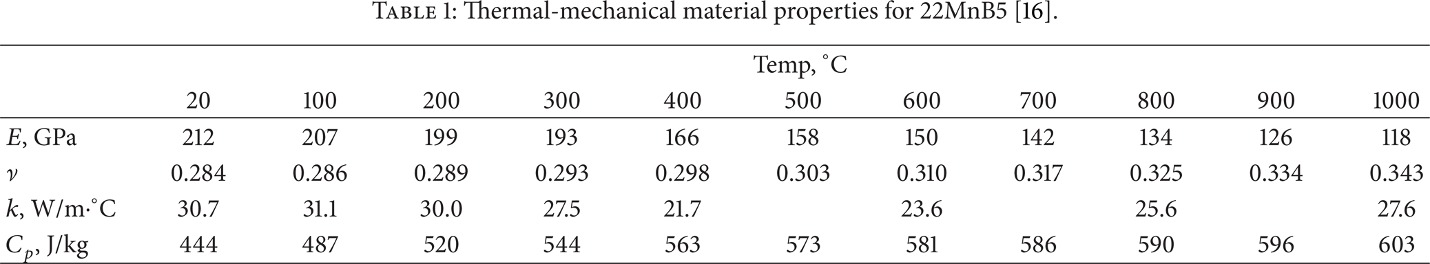
In the automotive industry, the quenchenable steel 22MnB5 is one of typical ultrahigh strength steel used in hot stamping. In this study, 22MnB5 sheet with thickness of 2 mm produced by BAOSteel was chosen. The mechanical properties were determined with Gleeble-3500 testing system at different elevated temperatures and strain rates. The test method followed [14, 15]. The stress-strain curves at different temperatures from 600°C to 800°C with the strain rates of 0.005 s−1 and 0.5 s−1 are presented in Figure 1. The density of 22MnB5 is 7830 kg/m3 and the thermal expansion is 1.3 × 10⁻⁵. Other thermomechanical properties of 22MnB5, such as Elastic modulus, Poisson ratio, heat conductivity, and specific heat are listed in Table 1 [16].
Thermal-mechanical material properties for 22MnB5 [16].
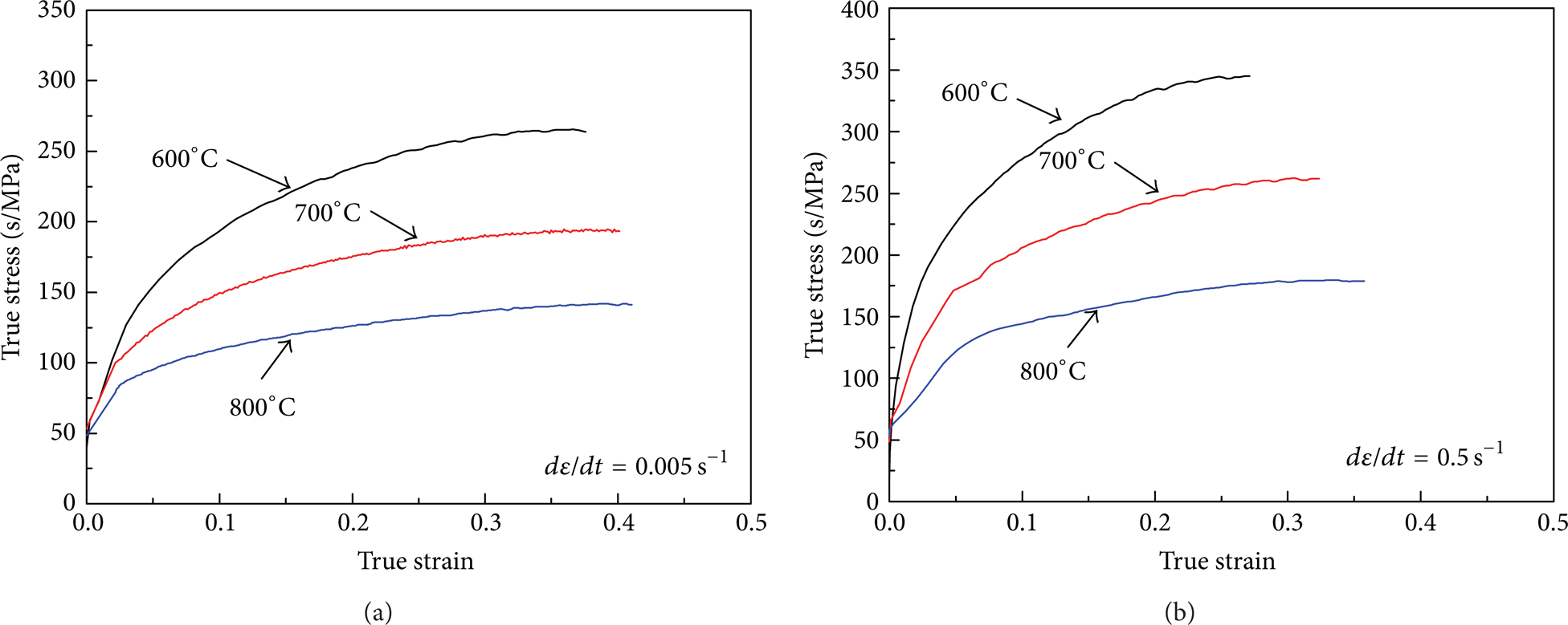
Flow curves of 22MnB5 at different temperatures with strain rates of (a) 0.005 s−1 and (b) 0.5 s−1.
The steel H13, which is widely used as hot forming tool steel, was chosen as the tool material in this paper. Its thermal-mechanical properties are as follows: the density is 7800 kg/m3, the Elastic modulus is 210 GPa, the Poisson ratio is 0.28, the thermal conductivity is 28.4 W/m·°C, and the specific heat is 560 J/kg. The thermal expansion is shown in Table 2 [17].
Thermal expansion of H13 steel [17].

Water is used as cooling medium. The cooling water properties are as follows: the density of water is 988.2 kg/m3, the viscosity is 0.001 Pa·s, the thermal conductivity is 0.6 W/m·°C, and the specific heat is 4182 J/kg.
3.2. Tools and Blank Model and Fluid Model
Considering the computing efficiency, firstly the hot stamping tools for U-shaped part were modeled and a transient thermal-fluid coupling analysis was carried out by MpCCI. In this way, the cooling system could be fast designed. The designed model includes the concept of the drilled cooling ducts [4].
The dimensions of the tools (punch, die, and holder) and the hot stamped workpiece are shown in Figure 2. A symmetrical model was built. The profile radius of the punch and the die are 8 mm and 10 mm, respectively. The draw depth is 20 mm. The cooling ducts are important factors influencing the cooling effect of the tools [8]. They should be arranged in a proper distance away from the hot formed workpiece regarding the cooling efficiency and the strength of the tools [4]. In this paper, the geometric parameters such as the distance between the tool surfaces and the cooling ducts (H) and the distance between the cooling ducts (S) and the diameter of ducts (D) (Figure 2) are considered as critical parameters for the cooling system design. The hot formed part is U-shaped. The latent heat from the workpiece was not taken into account. The run-in phase is six cycles, and that is 60's.
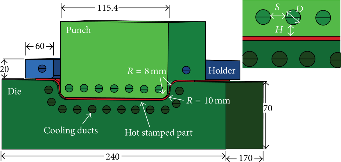
Schematic of the hot stamping tools, the hot formed workpiece, and the geometric parameters for the cooling system design.
The FEM models for the tools, the part, and the cooling water are shown in Figure 3. The tools and the part were meshed with hex 8-noded solid element in Abaqus. The minimum element size is 2 mm. The convection heat transfer to the environment is 30 W/m2·°C. The model of cooling water was meshed in Gambit with hex 8-noded solid element. The minimized element size is 1 mm. The velocity of water at the inlet of pipes is 1 m/s such that a turbulent state occurs in ducts. Both the environment temperature and tool temperature are 27°C. The initial temperature of the cooling water is also 27°C. The IHTC between the workpiece and the tools is the function of the workpiece temperature and the pressure. It can be gotten by an inverse method [18–21]. Limited by experimental condition, the IHTC curve obtained (Figure 4) is at a fixed pressure of 40 MPa. The IHTC result is close to the result from [3]. And the IHTC data from [3] are used in the thermal-fluid-mechanical simulation.

The FEM models of the tools, the part, and the cooling water based on MpCCI: (a) models and (b) flow chart of the simulation.

IHTC verses workpiece temperature under a contact pressure of 40 MPa.
Only the quenching process in closed tools was concerned while the forming process was not considered as it takes very short time (1∼2's). The temperature of the hot stamped workpiece is 850°C [8]. Six cycles of quenching phase were simulated to reflect the thermal cycles of the tools and the workpiece in the practical production. As is shown in Figures 3(a) and 3(b), the MpCCI (Mesh-based parallel Code Coupling Interface) is used to exchange the required data between the solid model in Abaqus and the fluid model in Fluent. Such data as the interface heat transfer coefficients between the water and the ducts and the coolant temperature are needed for the thermal simulation in Abaqus. These data are calculated by the model in Fluent and then transferred to the duct wall (element face) in Abaqus by MpCCI. In turn, the model in Abaqus offers the necessary results or data used in the thermal-fluid simulation in Fluent, such as the time step and the wall temperature of the ducts. And the coupling procedures are as follows. At the beginning, the transient thermal-fluid simulation is conducted in Fluent. And the results of the interface heat transfer coefficients on the duct wall are transferred to Abaqus by MpCCI. Next, the transient thermal simulation is carried out in Abaqus. Then, the data, such as the duct wall temperature, are sent to Fluent for the simulation of the next time step. Turn by turn, the two simulations are carried on until all the quenching phases are complete.
4. Results and Discussion
4.1. Design of Cooling System
The cooling rate of the workpiece and the temperature distribution of the tools are most cared because the property and the microstructure of the hot stamped workpiece and the service life of the tools are dependent on the temperature evolution. In the paper, the dimension and the location of the cooling ducts were analyzed for the cooling system design.
After six cycles, the temperature field in the workpiece becomes a steady state. It can be seen from Figure 5 that the cooling rate of the workpiece is greater than the critical cooling rate of 30°C/s [1] and varies along the section of the part. This is because of the high IHTC between the tools and the workpiece and between the tools and cooling water. The cooling rate at the bottom (positions 1, 2, and 3) is higher than that at the fillet of die (position 4), because the workpiece at bottom is cooled down by both the punch and the die [17]. Both the cooling rates in position 1 (just below the ducts) and in position 2 (below the gap of the ducts) are the same, which means that the cooling performance of the tools is uniform. So the hot stamped workpiece could have a uniform property, finally.

Temperature evolution of the workpiece during quenching phases (6th).
(1) The Influence of the Distance between the Cooling Ducts and the Tool Surface (H) on Temperature Evolution of the Workpiece and the Tools. Figure 6 shows the effect of the distance between the ducts and the tool surfaces (the distance “H”) on the temperature evolution of the workpiece and the tools. Figure 6(a) shows the result that the cooling rate of the workpiece becomes higher with the decrease in the distance. So the hot workpiece is cooled faster when the ducts are located more closely to the tool surfaces. Figure 6(b) shows thermal cycle of the punch and the die. The maximum temperature becomes lower with the decrease in the distance “H”. This is because the heat of the tools could quickly be dissipated when the cooling water is close to the workpiece. With the distance of 8 mm, the temperature of the tools could be around 200°C.

Temperature evolution with different distance between the tool surfaces and the workpiece (H).
(2) The Influence of the Distance between Ducts (S) on Temperature Evolution of the Workpiece and the Tools. Figure 7 shows the effect of the distance between ducts (the distance “S”) on the temperature evolution of the workpiece and the tools. In Figure 7(a), the cooling rate of the part becomes higher when the distance between ducts is decreased from 10 mm to 6 mm, because more ducts could be drilled in the tools. However, once the distance “S” is smaller than 8 mm, the cooling capability of the tools will not be increased as much as expected, and the cooling rate of the part grows little. The temperature curves of the tools show the similar trend (Figure 7(b)). The tools with few ducts are hotter. So the tools could be cooled effectively with a proper distance between cooling ducts, such as 8 mm, considering both the cooling efficiency and the strength of tools.

Temperature evolution with different distances between ducts (S).
(3) The Influence of the Duct Diameter (D) on Temperature Evolution of the Workpiece and the Tools. Figure 8 shows the effect of the diameter of the ducts on the temperature evolution of the part and the tools. The results show that temperature history curves of the workpiece with different diameters are similar. The thermal cycles of tools with different duct diameters are also very close to each other. In Figure 9, the reason for the little effect of the diameter of the duct is shown. Although the total discharge of the ducts with bigger diameter is larger, more cooling ducts with smaller diameter could be placed in the tools, which mean that there are more effective cooling zones at the bottom of the ducts [22]. Additionally, the turbulent state of cooling water in smaller ducts is more intensive so that a little higher IHTC is obtained on the wall. Consequently, the overall cooling performance of the ducts with small diameter (8 mm) is as effective as that with large diameter (10 mm).

Temperature evolution with different duct diameters (D).

The cooling zones of the ducts with diameters of 8 mm and 10 mm (H = 8 mm and S = 8 mm).
4.2. Thermal Deformation of the Tools with the Designed Cooling System
Based on the results above and taking into account the machining difficulty for drilled channels, the parameters (D = 8 mm, H = 8 mm, and S = 8 mm) were chosen as the designed geometrical parameters so as to obtain uniform temperature distribution and to keep the strength of the tools. The hot stamping tools for box-shape part are made (Figure 10). Two thermocouples placed in the tools are 4 mm away from the loaded contour.

The designed cooling system in the tools for hot stamping experiment.
Figure 11 shows the FEM model for thermal-fluid-mechanical coupled analysis. A symmetrical solid model was built with hex 8-noded solid element in Abaqus. The initial size of the blank is 240 mm × 170 mm × 2 mm (length × width × thickness). The corresponding model of the cooling water was built in Fluent, in which the element size is 1 mm. The thermomechanical simulation and the thermal-fluid simulation were carried out in Abaqus and in Fluent, respectively, and the MpCCI was used for exchanging thermal data between the two models. The initial temperature of the workpiece for hot stamping is 850°C. The cooling water velocity is 1 m/s. Other parameters refer to Section 3. The forming phase is considered in order to analyze the deformation of the hot stamping tools with the cooling ducts. And the IHTC with different pressure used referred to [3] for the thermal-fluid-mechanical simulation for tool deformation analysis.

The FEM models for box-shape workpiece based on MpCCI.
Figure 12 shows the experimental and FEM temperature results of the workpiece and the tools. In Figure 12(a), it can be seen that the calculated temperature result of the workpiece is consistent with the experimental result. An average cooling rate of 217°C/s was obtained, which is higher than the critical cooling rate of 22MnB5. As are shown in Figures 4(a) and 15(b), the reason for high cooling rate is that both the IHTC between the workpiece and the tool and the IHTC between the tool and the water are very high so that the heat of the workpiece is quickly absorbed by the tools and rapidly taken by the cooling water. It can be known that the martensitic transformation will be finished quickly and the strength of the automotive parts will be very high under such cooling condition. This proves that the design of the punch/die with cooling system is reliable.
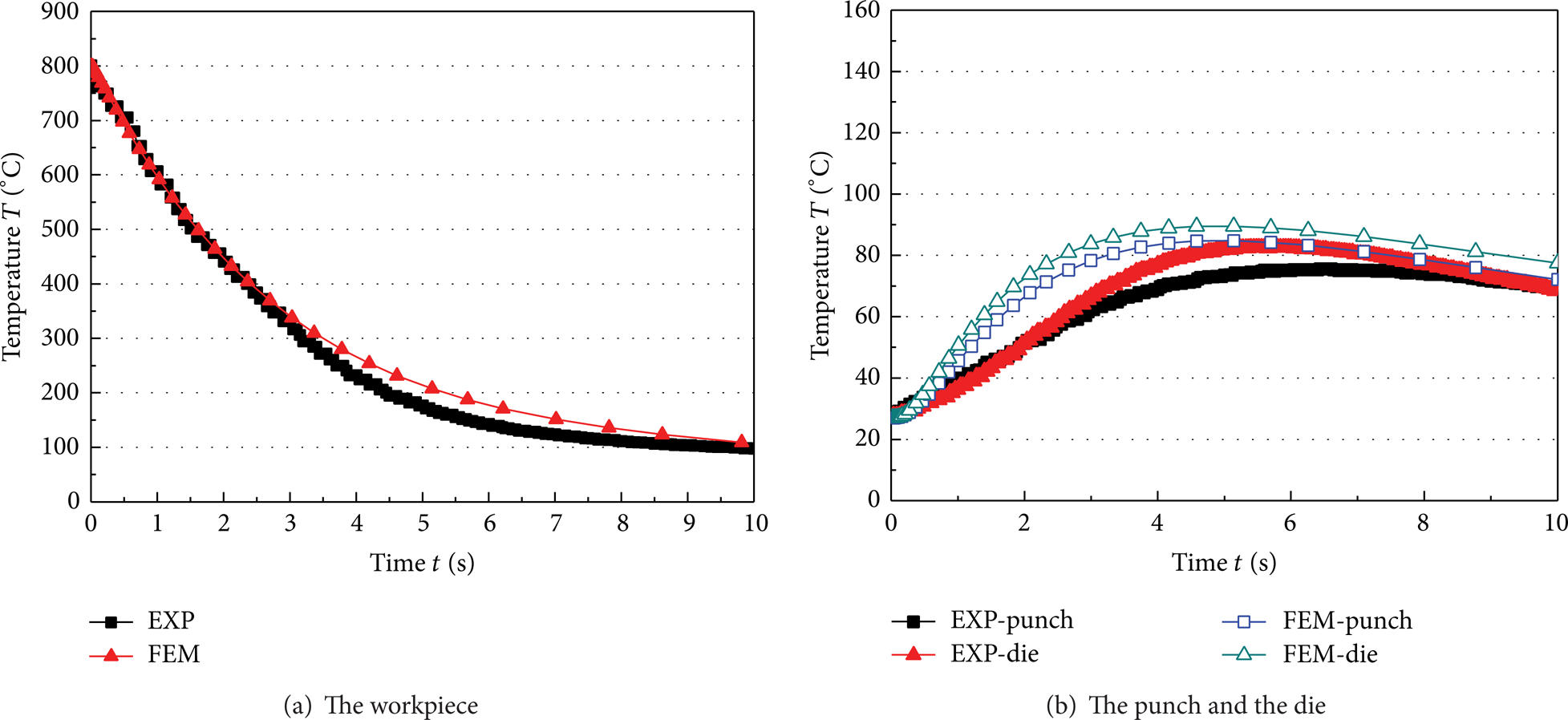
The experimental and FEM results for temperature evolution of the workpiece and the tools.
Figure 12(b) shows the tool temperature comparison between numerical results and experiments. It is shown that both the simulation curves and the measured curves have similar trend. The highest temperature appears in the few seconds (4's∼6's), which is lower than the required temperature of 200°C [2, 3] because of the high IHTC on the cooling duct wall. The hot tools are quickly cooled down so that the long sever life and the effective cooling performance of the tools could be ensured. The temperature deviation is about 15°C and the hottest point of experiment results emerges later than the FEM results. This is because the thermal couple rods are used in experiment. The rods are inserted in the holes of the tools. At the bottom of the holes, the rods are touched with the tools. So an average local temperature was measured around the bottom. Another probable reason is that the thermal properties of the tools for simulation are constant value.
In this paper, the punch was chosen to illustrate the deformation of the tools. The temperature distribution and thermal deformation of the punch are shown in Figure 13. Figure 13(a) shows that the punch is heated mainly in the area covered by the hot workpiece. Around the corner of the punch, the maximum temperature is about 300°C while the temperature of the other area of the punch remains low. Consequently, in the heated area, the punch expends in longitudinal direction and in width direction, and the other cold area of the punch has little deformation. The thermal deformation easily leads to the wear at the round corner of the tool.

Temperature distribution and thermal deformation of the punch (scaled 50 times).
Figure 14 shows the deformation and the stress distribution of the cooling ducts. The results in Figures 14(a) and 14(b) show that the ducts near the bottom of the punch are distorted in the longitudinal direction and in the width direction. This distortion is coincident with the punch deformation and caused by the expansion of the punch. In Figure 14(c), it can be seen that the highest stresses are around the right sharp corner of the ducts (position 2), near the convex of the punch. Also, there are high stresses in duct near the middle of the punch (position 4) and at the inlet (position 1). But the stresses are lower in the left corner of the ducts (position 3). The temperature along the duct is nonuniformly distributed. In the corner of the duct (positions 2 and 3), the temperature is higher because of the low IHTC at the corner (shown in Figure 15(b)).

The deformation and stress distribution of the cooling ducts.
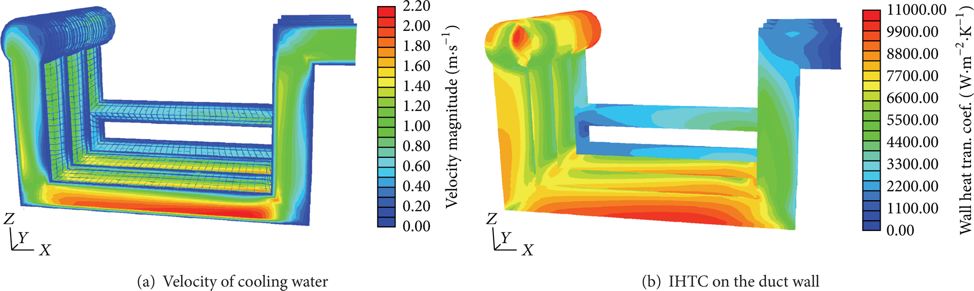
The velocity distribution and the IHTC distribution along the ducts.
By comparison of the stress and the temperature along the duct, it can be seen that the reason for the high stresses in duct lies not only in the thermal deformation due to temperature difference on the duct wall but also in the duct distortion caused by the punch expansion; for example, stresses are higher in positions 1 and 4 where there is lower temperature.
The stress concentration in the drilled cooling ducts is harmful. During the serial production, the life of the hot stamping tools will be shortened because of the thermal mechanical fatigue caused by this problem. One way to avoid the stress concentration is to manufacture the hot stamping tools by using the cast-in method or the shell structure method. In this way, the corner of the cooling ducts is made more smoothly, and the stress concentration can be removed.
As is shown in Figures 15(a) and 15(b), the flow state of the water has a direct effect on the cooling of the tools. The velocity of the water increases by 120% when the water flows through the cooling ducts. The maximum flowing speed is 2.20 m/s at the duct bottom while the velocity is very low at the right corner (position 2), and it is about 0.5 m/s. At the bottom, the flowing water holds a turbulent state which means a higher IHTC than that at the corner. High cooling velocity is good for the tool cooling and production efficiency. In contrast, the water temperature at the corner (position 2) will become higher because of the slow flowing water. This is called “hot spot” which reduces the cooling performance of the tools at the round corner and easily causes the crack of the ducts. This problem can also be removed by using the cast-in method or the shell structure method.
5. Conclusions
In this paper, a new multifield modeling method considering fluid field has been introduced to design the cooling system of the hot stamping tools and to analyze the cooling performance and the deformation characteristics of the tools. The following main contribution of this paper and conclusions can be drawn.
The parameters of the cooling system such as the diameter of the ducts, the distance between the ducts, and the distance between the ducts and the tool surfaces were designed. The cooling rate of the workpiece is higher and the temperature of the tools is lower when the cooling ducts are located more closely to the tool surfaces.
The cooling effect of the tools and the workpiece is also improved by more ducts placed in tools as the distance between ducts is smaller. The cooling behaviors of the workpiece and the tools are similar when the diameter of the duct is chosen from 6 mm to 10 mm.
The temperature evolution result of the FEM model was in good agreement with the experimental result. The cooling rate of the hot stamped workpiece was 217°C, higher than the critical cooling rate of martensite transformation of 22MnB5. The highest temperature of the tools was below 100°C. So the cooling performance of the hot stamping tools with cooling system met the practical production requirements.
Thermal expansion mainly occurred in the heated zone of the tools. This led to the distortion of the cooling ducts and stress concentration at some rectangular corner of the ducts. This problem can be avoided by using the cast-in method or the shell structure method to make hot stamping tools.
The water velocity increased by as much as 1.2 times when cooling water flowed through the bottom ducts. The cooling effect of the tools was enhanced in the area. By contrast, the cooling water flowed slowly at the corner of the cooling ducts, and the “hot spot” appeared which could affect the cooling performance and the life of the hot stamping tools.
Conflict of Interests
The authors declare that there is no conflict of interests regarding the publishing of this paper.
Footnotes
Acknowledgment
This work was funded by the National Natural Science Foundation of China (no. 51034009). These supports are gratefully acknowledged.