
Abstract
A new approach to optimizing a double-channel pump was presented, based on combined use of orthogonal test, computational fluid dynamics (CFD), and experimental analysis. First, a preliminary pump was designed according to design specifications, implementing the traditional design method. Later, a standard L9 (34) orthogonal table including 9 representative design schemes was implemented to find the best parameter combination for the impeller of the pump. Reynolds averaged Navier-Stokes equations accompanied by Smith modified k-ε turbulence model were solved to obtain the inner flow fields of the pump as well as its hydraulic performance for each design scheme. The optimized design scheme was obtained after range analysis. Finally, CFD analyses and experiments were carried out to evaluate the optimized design. The results show that the characteristics of the optimized pump were obviously improved, and the simulated pump head and efficiency increased by 3.622% and 9.379%, respectively. This research not only provides an effective way to improve the hydraulic design of double-channel pumps, but also has certain reference value in multiobjectiveoptimization design of other pumps.
1. Introduction
The double-channel pump is a special form of centrifugal pump, and its impeller consists of two symmetrical flow passages. Due to its good passing ability, it is widely used in the city sewage and industrial waste water transportation and processing area. Therefore, with the enhancement of common environment awareness, researches on design and development of the double-channel pump attract more and more attention.
The design of double-channel pumps requires the accomplishment of several targets and constraints. A high level of efficiency and nonclogging performance must simultaneously be achieved, while keeping manufacturing costs low and guaranteeing a high level of reliability. However, due to the lack of mature design theory, the design method of double-channel pumps still remains conventional and relies greatly on the designer's empiricism. This leads to a low level of efficiency, usually 3%∼8% lower than ordinary blade centrifugal pumps [1].
As proved in other studies [2–7], computational fluid dynamics (CFD) can give a lot of potentially very useful information for improving the fluid dynamic design of pumps. However, in many cases, it does not directly state what kind of modification should be made to improve such hydrodynamic performance. Thus, the design of a double-channel pump or the modification of an existing one still remains very conventional at the present stage, depending heavily on the designer's intuition, empiricism, and background data with a time-consuming trial and error method.
A more convenient and effective approach is proposed in this paper for the design and optimization of a double-channel pump by combined use of orthogonal test, CFD, and experimental analyses. First, a preliminary pump is designed according to the design specifications, implementing the traditional double-channel pump design method. Next, the impact of main geometrical parameters on the pump hydraulic performance is analyzed by combined use of orthogonal test and CFD simulations. Finally, the preliminary design is optimized on the basis of the orthogonal test and CFD results, aiming at maximizing the hydraulic efficiency, while guaranteeing the pump head. An experimental analysis is also carried out on the last design and the results are compared with the numerical predictions.
2. Preliminary Design
The double-channel pump under investigation is composed of a double-channel impeller and a spiral volute. Its design specification is given as follows: flow rate of 50 m3/h and head of 10 m at a rotating speed of 2900 rpm.
2.1. Impeller Design
As shown in Figure 1, the impeller is composed of two symmetrical flow channels, and each channel is composed of channel-in and channel-out.

Meridional view (a) and plane view (b) of the impeller.
The main geometrical parameters on the meridional view of the impeller are designed by the following equations [8, 9]:

where K Dj , KD2, and Kb2 are constants and decided according to the designer's empiricism. R1 and R2 are designed according to Figure 2. T1 and T2 are directly set to be 87° and 90°, respectively.
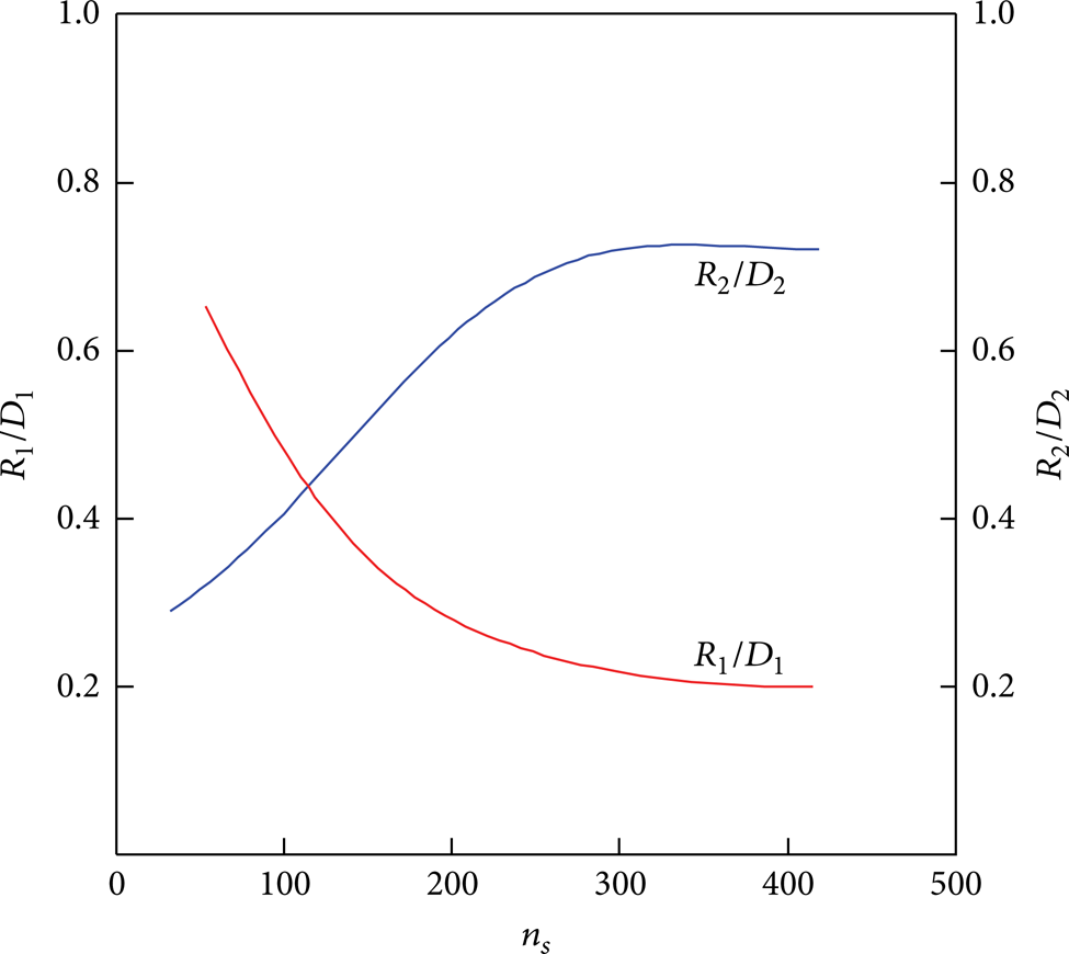
R1/D1 and R2/D2's relation with ns.
The channel midline on plane view of the impeller is governed by the following equation:
where r represents polar radius, θ represents polar angle, a is a constant, a = D2/(2ψ m ), m is a coefficient which depended on ns, and ψ is the wrap angle of midline which also depended on ns, shown in Figure 3.

m and ψ's relation with ns.
Channel-in is formed by sweeping eight oval cross sections, and their areas change with the following straight line F0F7, shown in Figure 4, where F0 represents the inlet area, equal to πD j 2/4, and F7 represents the outlet area, equal to F0/2. Finally, a blade thickness variation rule on plane view of the impeller is given, which governs the shape of channel-out.
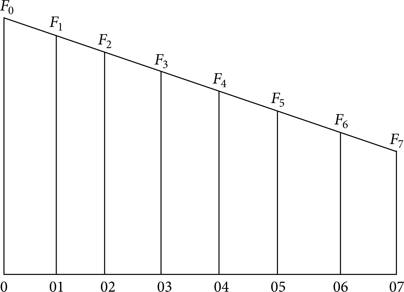
Change rule of channel-in section areas.
2.2. Volute Design
A spiral volute (see Figure 5) is designed for the double-channel pump because of its wide high efficiency area. In order to improve the passing ability at the volute throat, relatively larger volute inlet diameter D3 and width b3 are designed according to the following two equations, respectively:
where t1 and t2 represent the thickness of shroud and hub at the impeller exit, respectively.

Spiral volute.
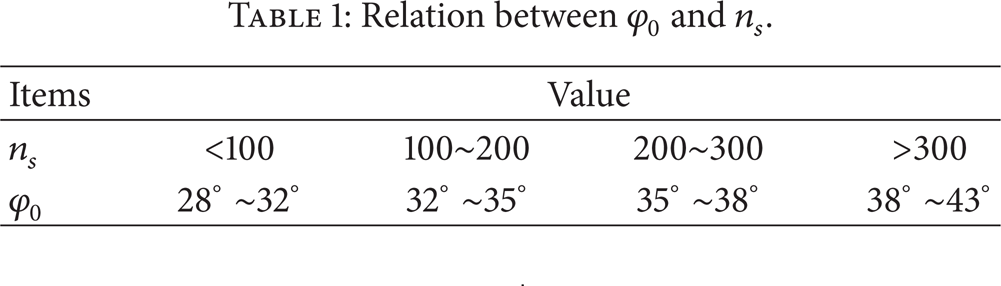
Parameter φ0 indicates the throat location and is designed according to Table 1.
Relation between φ0 and ns.
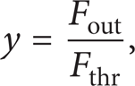
From previous research, the throat area of volute has great influence on the double-channel pump's hydraulic performance. According to Anderson's definition,

where Fout represents the impeller exit area, Fthr represents the throat area of volute, and y is the area ratio coefficient and can be calculated by
2.3. Design Results
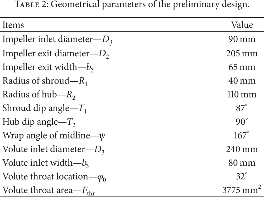
The main geometrical parameters of the double-channel pump are listed in Table 2.
Geometrical parameters of the preliminary design.
3. Numerical Analysis
3.1. CFD Method
In order to validate the preliminary design, CFD method is used to simulate the 3D flow field in the pump and it predicts the hydraulic performance for a variety of flow rates [10, 11].
The CFD code used in the present paper is a self-developed SIMPLEC code for steady or unsteady, compressible or incompressible turbulent flow, which solves Reynolds averaged Navier-Stokes equations using k-ε turbulence model modified by Smith for curvature and rotation. A mixing plane model is incorporated into the code to simulate the turbulent flow within the double-channel pump having a rotating impeller and a stationary volute. The velocity, turbulent kinetic energy, and turbulent dissipation rate terms are discrete by the second order upwind differencing scheme, while pressure term is discrete using the second order central differencing scheme. Convergence is based on reducing the maximum of the normalized residuals of the momentum and continuity equations to less than 10−5.
The computational domain is extended upstream and downstream (see Figure 6) to avoid the influence of boundary flow. A uniform inlet flow distribution is assumed by setting the inlet flow velocity and a turbulence density of 5%. For the outlet, it is assumed as a free flow outlet without pressure gradient along its flow direction, and static pressure is set to be 0 here as the reference pressure for calculations. For wall boundary, nonslip wall boundary condition is imposed.

Calculation domain and grid.
In order to validate the design for a variety of the flow rates, the computational grid size for CFD needs to be minimized to reduce CPU time. A relatively coarse grid is used in the present paper. The number of the grid points is 1,065,525 for the original design. Additional calculations are carried out using 900,000 more grid points for grid independency tests, and it is confirmed that the difference in overall performance and the flow field is very small. The predicted pump head and efficiency difference between these two grid cases is only 0.1486% and 0.0978%, respectively. The first cell point is located in the fully turbulent region corresponding to local y+ value larger than 11.5, and the logarithmic law is employed to estimate the wall shear stress.
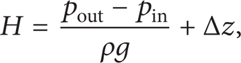
From pump operation principle, the practical and theoretical pump head can be calculated by the following two equations, respectively:

where pin and pout are area averaged total pressure at the inlet and outlet, respectively, Δz is the vertical distance between the inlet and outlet, M is the total moment at the rotational axis z, ϖ is the impeller rotational velocity, H is the pump head, and H t is the theoretic pump head.
Thus the efficiency of the pump can be obtained from the following equation:
It should be noted that the effects of leakage flows through wearing rings and seal rings as well as the disk friction action on the impeller hub and shroud back surfaces are neglected in the simulations, since all these effects are identical for all design cases and do not affect the relative comparison of pump performance.
3.2. Discussion of Preliminary Design
Figure 7 presents the velocity vectors in the double-channel pump predicted by CFD. Although the flow rate is that for the design point, unfavorable large separation vortexes are observed (Region A B in Figure 7(a)), as well as secondary flow (Region C D E F in Figure 7(b)).

Velocity distribution in the double-channel pump.
Figure 8 shows the static pressure contours in the double-channel pump. Low static pressure fluids, generated in the fore part of the blade suction surface, are brought into the hub due to the secondary flows. Downstream from this region, the adverse pressure gradient becomes high in Region A B in Figure 7(a). The thick viscous layer, generated by the accumulation of low total pressure fluids, is less resistant against the adverse pressure gradient, and the flow is separated at this region.
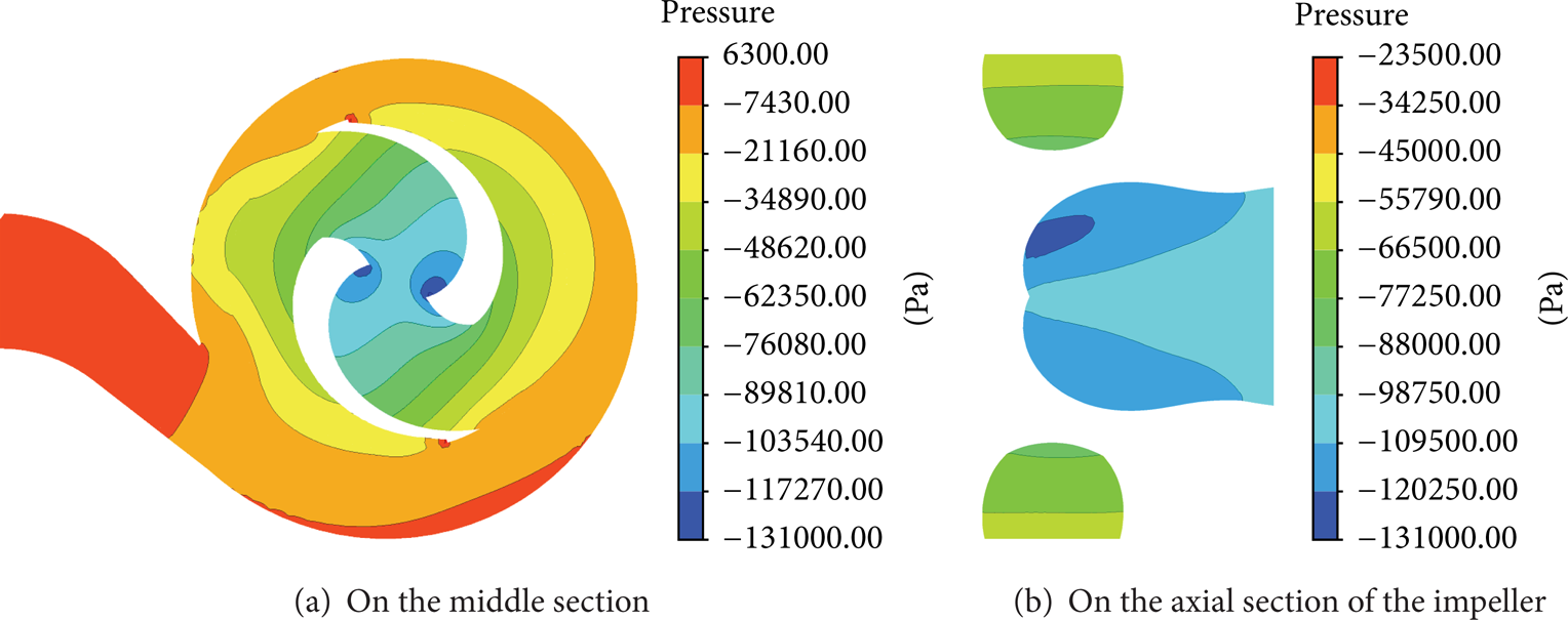
Static pressure contours in the double-channel pump.
Figure 9 shows simulated hydraulic performance of the preliminary pump, which indicates a rapid head decline in the large flow rate area, and a narrow high efficiency region. And the maximum efficiency of the pump is not obtained at the design point as expected.

Hydraulic performance curves of the preliminary pump.
4. Optimization by Orthogonal Test
4.1. Orthogonal Test Approach
Orthogonal test approach is a kind of optimization design method of multiple factors and multiple levels. In this approach, numerical or experimental tests are done on representative test points, which are selected based on the orthogonality of the comprehensive test points. In this way, the optimal design case can be found after fewer times of tests. Thus, it is an efficient, fast, and economical optimization approach and has been successfully used in optimization design of other pumps [12, 13].
In the case of double-channel pump, it is a special centrifugal pump with a lot of geometrical parameters related to its hydraulic performance. If all design cases through the combination of geometrical parameters are manufactured and experimented, it will cost much money and time. Thus, orthogonal test is used in this paper to find the best parameter combination for the double-channel pump based on CFD results.
4.2. Test Factors and Scheme
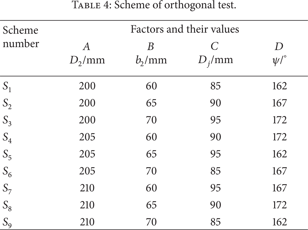
From Table 2, the main geometrical parameters related to the hydraulic performance of the double-channel pump include the following: impeller inlet diameter D j , impeller exit diameter D2, impeller exit width b2, volute inlet diameter D3, and volute inlet width b3. Since the double-channel pump is different from ordinary centrifugal pump mainly for its impeller, 4 main geometrical parameters of the impeller are chosen as design parameters (i.e., factors of orthogonal test), and each design parameter has 3 levels; see Table 3. A standard L9 (34) orthogonal test table is used as the test scheme; see Table 4.
Factors of orthogonal test.

Scheme of orthogonal test.
4.3. Optimization Objective
According to the design principle of the double-channel pump, the pump head and hydraulic efficiency must be accomplished simultaneously, which results in a multiobjective optimization problem. A new integrated hydraulic performance indicator F is introduced in this paper, which takes both pump head and efficiency into account in a dimensionless form as


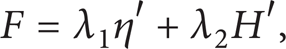
η′ = η/ηpre is dimensionless efficiency, H′ = H/Hpre is dimensionless head, ηpre is efficiency of the preliminary pump, Hpre is head of the preliminary pump, λ1 is weighting factor of efficiency, and λ2 is weighting factor of head.
4.4. Orthogonal Test Results and Discussion
4.4.1. Hydraulic Performance of Nine Schemes
CFD method is used to obtain the hydraulic performance of the pump for 9 schemes listed in Table 4 for a variety of flow rates, and the results are shown in Table 5 and Figure 10.
Summary of data at the design point.


Hydraulic performance of 9 schemes.
4.4.2. Direct Analysis
From Table 5, it is observed that, at the design point, all schemes can satisfy the efficiency standard according to GB/T 13007-91, as well as the pump head requirement.
From Figure 10, it is found that (1) head of scheme 7 is the largest in the small flow rate region, while head of scheme 8 is the largest in the large flow rate region; (2) efficiency of each scheme changes little in the small flow rate region, while it differs a lot in the large flow rate region; (3) efficiency of scheme 1 is the largest in this region. From the above, it is difficult to decide which one is the best scheme, and further range analysis is necessary.
4.4.3. Range Analysis
Range analysis, which can reflect the influence degree of factors and levels on orthogonal test index, is used here to analyze the hydraulic performance obtained at the design point of 9 schemes listed in Table 5, and the results are shown in Table 6, where indicator ki represents the averaged hydraulic value for each factor at level i(i = 1, 2, and 3) and R represents the difference between the maximum and minimum k for each factor.
Range analysis of data at the design point.
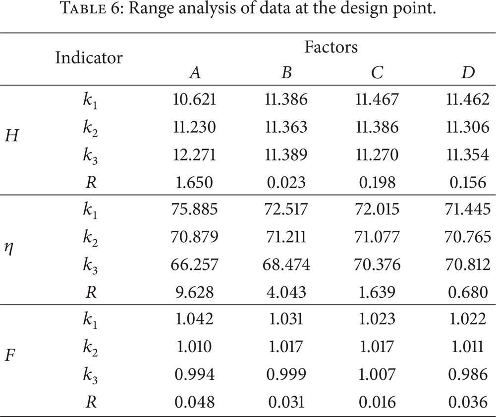
From this table, several conclusions can be made: (1) the importance order of design parameters for the head is A>C>B>D, and A3B3C1D1 is the best scheme for the head; (2) the importance order of design parameters for the efficiency is A>B>C>D, and A1B1C1D1 is the best scheme for the efficiency; (3) the importance order of design parameters for the indicator F is A>D>B>C, and A1B1C1D1 is the best scheme for the indicator F.
Since the ultimate optimization objective is to design a double-channel pump with maximum efficiency on the premise of satisfying the head, A1B1C1D1 is the best scheme for this optimization purpose; that is, the best combination of design parameters is the following: D2 = 200 mm, b2 = 60 mm, D1 = 85 mm, and ψ = 162°.
5. Validation of Final Design
5.1. CFD Analyses
To validate the final design, the CFD method introduced above is used to simulate the complex 3D flow field in the final design for 3 typical flow rates (Q = 0.8Q d , 1.0Q d , and 1.2Q d ). And the simulation results are compared with the preliminary design, shown from Figures 11, 12, 13, and 14. Some conclusions can be made: (1) there is no obvious flow separation vortex in the pump of the final design at the design point; (2) secondary flow in the impeller is greatly alleviated for all flow rates, especially at the design flow rate; (3) static pressure, which gradually increases from the impeller inlet to the outlet in the preliminary design, has a less gratitude from the pressure side to the suction side of the flow channel in the final design.

Comparison of static pressure contour on the middle section of the optimal and original pump.

Comparison of flow lines on the middle section of the optimal and original pump.

Comparison of static pressure contour on the axial section of the impeller of the optimal and original pump.

Comparison of velocity vectors on the axial section of the impeller of the optimal and original pump.
5.2. Experimental Validation
Finally, a real pump is manufactured according to the final design and tested in the pump testing centre of Jiangsu University (China). The tested characteristic curves of the pump are shown in Figure 15, compared with the simulated results.

Simulated and tested hydraulic performance of the optimized pump.
It is found that (1) since the leakage flows through wearing rings and seal rings and the disk friction are neglected in the simulations, differences between the tested and simulated results exist; (2) in the small flow rate, the simulated data correspond well with the tested data, with a maximum deviation of 9% and 5% for the efficiency and pump head, respectively; (3) with the flow rate increases, although the difference between the tested and simulated results increases, their variation tendency is almost the same; (4) compared with the hydraulic performance of the preliminary design (Figure 9), simulated pump head and efficiency obviously increase for all flow rates, with an increase of 3.622% and 9.379% at the design point for the pump head and efficiency, respectively; (5) the pump head declines more gently in the large flow rate region than the preliminary design, and a broader high efficiency region is also observed; (6) the tested maximum efficiency of the pump equal to 69.942% is obtained at the design point.
6. Conclusions
The predicted flow fields by CFD give a lot of potentially useful information for improving the fluid dynamic design of double-channel pumps. However, it is not very clear what kind of modification will most effectively improve the flow fields as well as the hydraulic performance of the double-channel pump. Traditional trial and error optimization method is time-consuming and greatly relies on the designer's empiricism. This paper presents a new design and optimization methodology based on the combined application of CFD analyses and orthogonal test optimization. The effectiveness of this approach is proven with the redesign of a double-channel pump with design specifications of Q d = 50 m3/h, H = 10 m, and n = 2900 rpm. Main conclusions include the following: (1) in preliminary pump, unfavorable large separation vortexes are observed even at the design point, which leads to a rapid pump head decline and a narrow high hydraulic efficiency region on the characteristic curves; (2) such separation is suppressed by applying the new design and optimization methodology. Thus, the pump head and efficiency of the final design pump obviously increase for all flow rates, the pump head declines more gently in the large flow rate region, and a broader high efficiency region is also realized with the maximum hydraulic efficiency point coinciding with the design point.
Conflict of Interests
The authors declare that there is no conflict of interests regarding the publication of this paper.
Footnotes
Acknowledgments
This work is funded by the National Natural Science Foundation of China (Grant no. 51109094) and the Priority Academic Program Development of Jiangsu Higher Education Institutions (PAPD).