
Abstract
Since time division multiple access (TDMA) is employed to reduce power consumption, time synchronization is critically important for wireless sensor networks. Packet-based clock correction is one of main methods to maintain synchronization among nodes. However, in many real cases, such as industrial equipment monitoring and diagnosis, there is no need to exchange messages during relatively long time, while highly accurate time synchronization has to be maintained, which results in that additional packets have to be exchanged specifically for synchronization purpose. For addressing this problem, an adaptive compensation method is proposed in this paper to achieve a high synchronization precision without exchanging message frequently. We proved that the adaptive compensation method can achieve a high synchronization precision with much fewer packet exchanges. In addition, the performance of the proposed scheme has been evaluated in three different experimental settings. In the indoor experiment, compared with the synchronization method without using compensation, 98% of the synchronizing packets can be eliminated while maintaining synchronization precision at 100 μs. In the outdoor experiment with higher temperature fluctuation, 80% of the packets can be eliminated with 100 μs synchronization precision. In the case of sudden temperature changes of more than
1. Introduction
As most wireless sensor networks (WSNs) [1] work with battery power, power consumption becomes a critical constraint for networks’ nodes. Since radio transmitting is major consumer of a node's energy [2], it is important to minimize the radio-up time when designing WSNs. A good design for a low power WSN should keep the radio off whenever possible and only turn on radio when actively transmitting or receiving packets.
To achieve this goal, synchronization is required. Time synchronization makes two nodes share the same sense of time; thus they can coordinate their radio activity to achieve low power. This is particularly important for battery equipped devices used for industrial application, which usually require more than 5 years of operation life. As one of such synchronization techniques, time slotted channel hopping (TSCH) is adopted by major industrial low power wireless standards such as WirelessHART [3], ISA100 [4], and IEEE802.15.4e [5].
TSCH protocols use an agreed upon transmission schedule between two nodes. Figure 1 shows the case of TSCH in IEEE802.15.4e. Time is split into equal length time slots; the slot frame is defined as a constant number of slots repeated over time. Each slot has an

In slot-based communication, time is sliced up into repeating frames. Each node is scheduled to communicate at a specific slot. The packet is scheduled to be sent at
Packet-based clock correction is one of main methods to maintain synchronization among nodes. Since packets are transmitted
Since clock drift will widen the synchronization error, nodes need to resynchronize frequently to maintain synchronization accuracy, which will cause bandwidth and energy consumption problems. Compensation is usually used to deal with such case. Nodes can stay synchronized through periodically adjusting the local clock at an opposite rate of drift. Many clock drift models are designed for compensation. Complicated models are heavy for a WSN node with limited resource and simple models make compensation inaccurate. In this paper, we propose a method to improve the accuracy of calculated drift through adjusting the interval of resynchronization, which is simple enough to be used in practice. This method, called
In next section, we show some synchronization methods in WSNs and the difference between those methods and
2. Related Work
Time synchronization in wireless sensor network is a well-studied field. Many algorithms for WSNs already exist. Reference broadcast synchronization (RBS) [7] is a protocol in which synchronization happened between receivers. The sender broadcasts a packet to a set of receivers. The receivers record the timestamp when the packet was received and exchange the timestamps with other receivers in the synchronization set. RBS minimizes the undetermined delay from the sender side which improves the accuracy of synchronization. Time-sync protocol for sensor network (TPSN) [8] is a different protocol with RBS, which records the timestamp in the MAC layer at the sender side. Two communicating nodes exchange packets using a two-way method. This pairwise synchronization can remove the propagation delay. Flooding time synchronization protocol (FTSP) [9] records timestamp in the MAC layer at both the sender and receiver sides. It removes all kinds of undetermined delays except for propagation delay. The timestamp is added as a final step after encoding/decoding the SYNC byte so the node can achieve a high accuracy of time synchronization. TSCH protocol in IEEE802.15.4e just uses FTSP as its synchronization method.
Those synchronization protocols focus on high accuracy of synchronization when exchanging packets. To maintain such high accuracy they have to resynchronize frequently to deal with clock drift, which consumes a lot of energy and bandwidth. Some adaptive synchronization algorithms, through estimating drift, adjust the local clock to counteract the clock offset without exchanging packets for resynchronization. By modeling the clock drift of daytime, [10] presents an adaptive synchronization to deal with drift. However, the model is built based on offline measurement. It cannot handle the dynamical variation of drift. Self-correction clock, which is shown in [11], is another method that made a hardware clock which can do self-correction to deal with drift. This obviously increases the cost of node.
The
3. Problem Definition
In general, compensation can be explained as periodically adjusting the local clock at a given rate, usually an estimated value of node's drift. For example, a node in a slotted network, which has a 32768 Hz crystal with a drift of 10 ppm faster than its time parent's crystal, can keep synchronization by shortening its current time slot duration by one tick (30 μs) every 3 seconds (Figure 2).

Compensation in time-slotted networks. The node's slot duration is 100 ticks. It compensates drift to its time parent by periodically shortening (or lengthening, if slower than its time parent) by one tick.
Since the temperature is the main factor influencing clock drift [12], drift can be considered constant in short-term or indoor environments where temperature fluctuations are small. In such environments, drift can be calculated by averaging a period of synchronization error as (1) shown.

The accuracy of
The


As our goal is to improve the accuracy of drift, what we need to do is diminish the value of
4. Adaptive Compensation
In this section, first we will show
4.1. Model of Synchronization Error with Compensation
The model of synchronization error with compensation is depicted below (4).


The key to answer the question is to know what time synchronization error will fall out of
As we have got the time, what we should do is schedule next synchronizing packet before T. However, we did not know the specific time point to guide node to schedule next synchronizing packet since
Actually
Figure 3 depicts the meaning of (7) in practice. When a node is synchronizing at
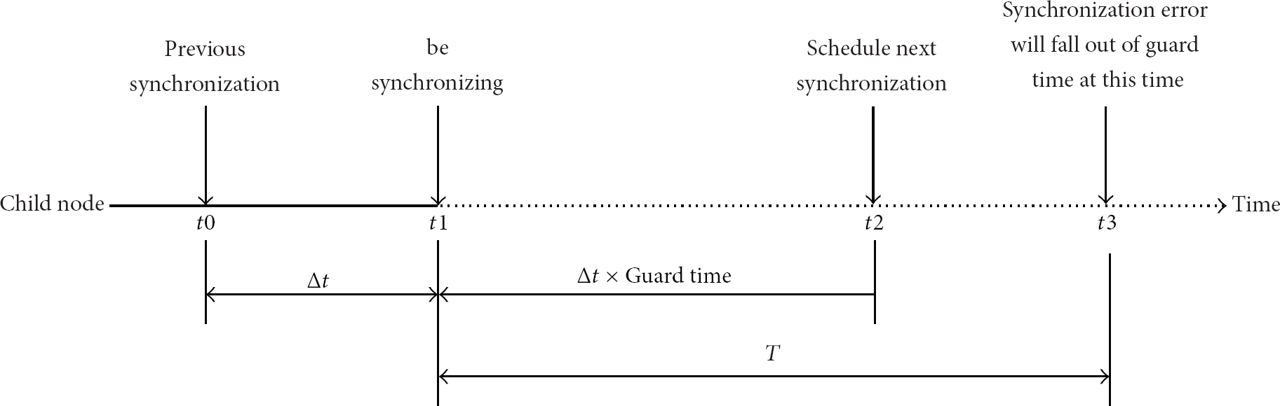
Current time is
The procedure to calculate drift is an iteration procedure. The expanded synchronizing interval improves the accuracy of calculated drift. On the other hand, more accuracy of drift delays the time point at which synchronization error falls out of
In the following section, we will discuss how nodes schedule their resynchronization packet according to (7) in practice and present a reboot mechanism based on temperature sensor to the temperature influence on clock drift.
4.2. Synchronization with Adaptive Compensation
To use this

When
When synchronization interval expands to some degree, the fluctuation of temperature will become more apparent. Crystal's drift will also fluctuate. In such case, (1) for calculating drift is not suitable yet. To deal with the influence of temperature, a reboot mechanism based on measurement of temperature is performed.
Using the equipped sensor, nodes can measure the temperature surrounding it periodically and compare it with the temperature which is recorded at last time when node exchanges packet for synchronization. Once nodes detect the fluctuation of temperature exceeding a threshold, it will send a packet to synchronize immediately and reset the synchronizing interval to initial value. Then
5. Implementation
We implemented
The hardware of this implementation is called GINA [13] platform which is made by Swarm Lab in UC Berkeley (Figure 4). GINA is a low-cost wireless node containing an MSP430F2618 [14] 16-bit microcontroller and a AT86RF231 [15] radio chip. An external crystal of 32768 Hz, with a drift of ±20 ppm, is used to provide a slot length of 10 ms.
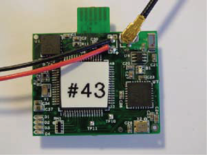
The guidance and inertial navigation assistant (GINA) platform is a low power wireless mote augmented with inertial measurement capabilities [13].
When implementing
Second is compensation. Since the drift is calculated by time slots, node can count the number of slots at the beginning of each slot. When the counter hits the value of calculated drift, the synchronized node will lengthen or shorten its current slot length by one tick for compensation. Another part is scheduling synchronizing packets. We can schedule the synchronizing packet with the timer in MSP430F2618. Once the timer fired, an interrupt is triggered to notify nodes to send a packet for resynchronization. The counter of timer will be reset to one time larger value which indicates next synchronizing interval.
The last part is reboot mechanism. There are kinds of sensor equipped on GINA, such as 3-axis gyroscope, 3-axis magnetometer, and temperature sensor. With the temperature sensor, we can detect the fluctuation of temperature and implement reboot mechanism on GINA. TMP20 [16], which is selected to be the temperature sensor of GINA, operates from −55°C to +130°C on a supply voltage of 2.7 V to 5.5 V with a supply current of 4 μA. The deviation would be
6. Evaluation
To evaluate the performance of
6.1. Experimental Settings
During experiments, slot boundary and synchronizing points are recorded by logic analyzer. Figure 5 shows a snapshot for a simple network of two synchronized nodes, which are running adaptive compensation implementation. Node A represents the time parent. The activities of two nodes are indicated by three digital signals:
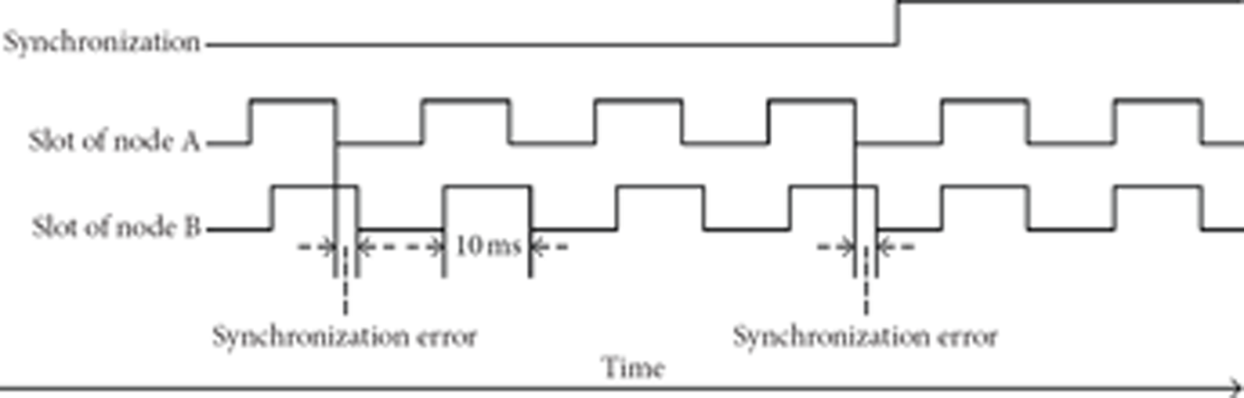
Logic analyzer records the implemented synchronization with gradually improved compensation procedure. Node A is the time parent.
Through comparing the slot boundary between nodes A and B, we can record the synchronization error of each slot. Matlab is used for statistics and analysis of the performance of
The experimental synchronized node has a drift of 12 ppm. Synchronization accuracy of 100 μs is needed to be maintained for the node. Synchronizing interval is initialed to 8 seconds and it would expand by 2 times when using

Temperature fluctuation in 24 hours indoor and outdoor and sudden change in temperature.
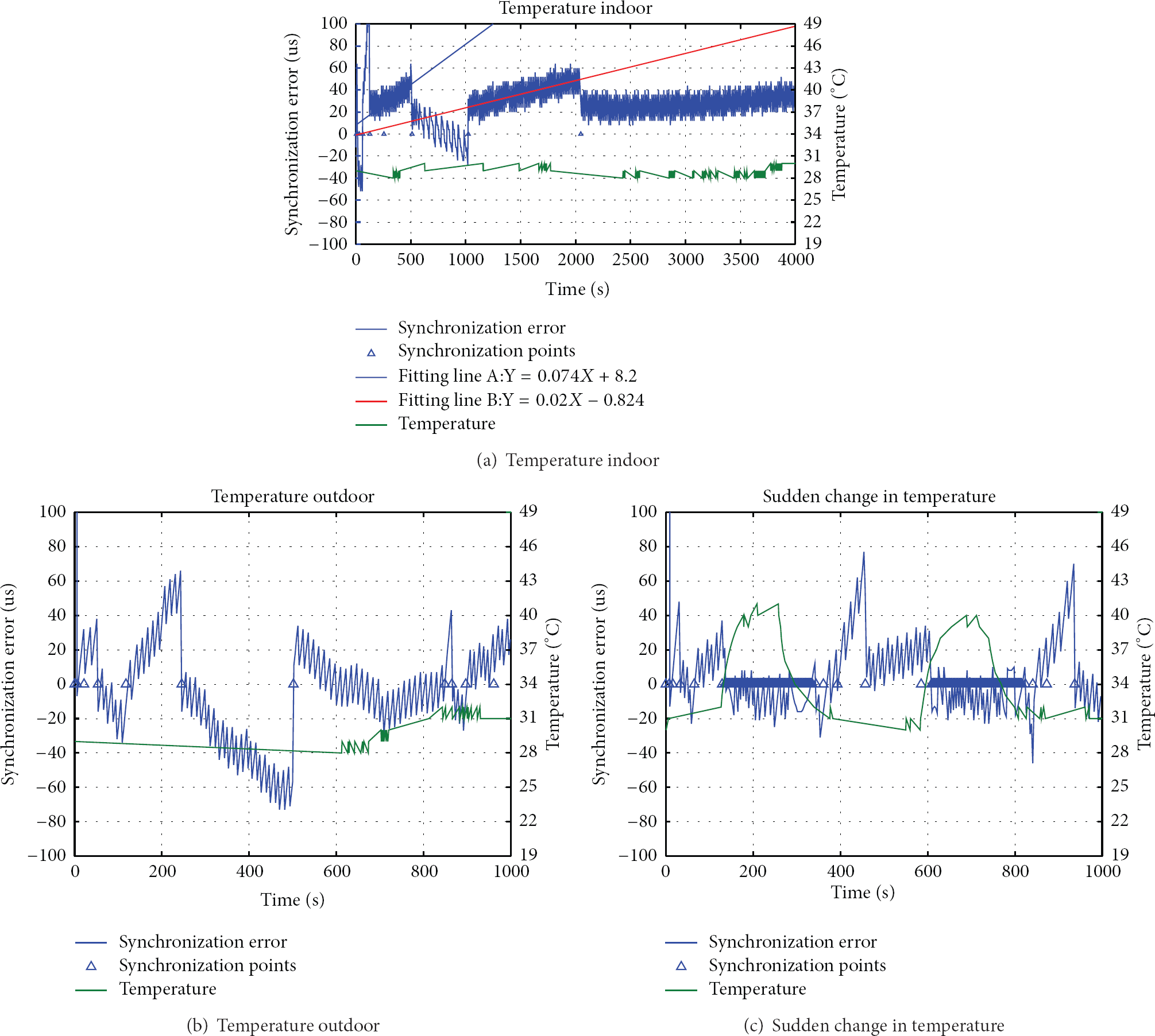
Synchronization error for three environments: indoor, outdoor, and sudden change in temperature.
6.2. Experimental Scenarios
6.2.1. Constant Temperature
To indoor environment, the temperature is usually considered as constant. As shown in Figure 6(a), temperature in 24 hours ranges from 25°C to 28°C and varies smoothly. In such environment, the temperature would not influence the drift of crystal. The indoor performance of
6.2.2. Temperature with Daily Fluctuation
Unlike indoor case, temperature will become more fluctuant by the influence of complicated outdoor environments. The daily temperature outdoor ranges from 22°C to 29°C as shown in Figure 6(b). Since many factors influence local temperature, like sunlight, shade, and winds, 2°C to 5°C fluctuation of temperature would happen occasionally. According to the result of experiments, those factors only allow resynchronizing interval to go up to few minutes when using improved compensation. The outdoor performance of
6.2.3. Sudden Change in Temperature
In some cases like industrial application, temperature may increase more than 10°C in less than one minute. To evaluate the performance of proposed method in such scenario, a hot-air gun was used to heat up synchronized node every 8 minutes (Figure 6(c)). Because of the great influence on clock drift, frequently packet-based resynchronizations are required to maintain synchronization. In such case, the performance of
6.3. Experimental Result
6.3.1. Constant Temperature
As shown in Figure 7(a), synchronization error increased more slowly after each resynchronization, which can be derived from the slope of fitting lines A and B. Synchronizing points are indicated by blue triangles. The synchronization error from the synchronizing points 255 s to 511 s and 1024 s to 2047 s is fitted by line A and line B. The slop of line B is smaller than line A, which means that the calculated drift at 1024 s is more accurate than the drift calculated at 255 s.
The slope of fitting line corresponds to
To indoor case, the synchronizing interval could increase to about one hour long. As the initial of synchronizing interval is set to 8 seconds, only 9 synchronizing packets are used during the period of one hour. If we only use packet-based synchronization, synchronizing packet needs to be sent about every 8 seconds to maintain synchronizing accuracy of 100 μs. Thus 450 packets are required in one hour. 98% packets could be eliminated by
6.3.2. Temperature with Daily Fluctuation
Since the fluctuation of temperature outdoor is heavier than indoor case, synchronizing interval can only expand to several minutes’ level and the reboot mechanism would be triggered then. Figure 7(b) showed the result of outdoor experiment. The tendency of synchronization error indicated the relationship between
Temperature fluctuated heavily after 600 s. The tendency of synchronization error was down after 250 s as calculated drift was greater than real drift. The fluctuation of temperature during 700 s to 800 s made real drift bigger than calculated drift and the tendency turned to up. At about 850 s, TMP20 detected the fluctuation of temperature exceeded the threshold of 2°C. Then the synchronized node reset synchronizing interval to 8 seconds and restarted the compensation procedure.
Because of the fluctuation of outdoor temperature, the synchronizing interval using improved compensation can increase to 4 minutes on average and 6 packets are required to maintain the accuracy of 100 μs. If we use packet-based synchronization only, 30 synchronizing packets are required in 4 minutes, and 80% of packets could be eliminated.
6.3.3. Sudden Change in Temperature
The performance of proposed compensation method when temperature changed suddenly is shown in Figure 7(c). When the great change of temperature happened on synchronized node, the node would send packet every second, the same rate with temperature sampling, to keep synchronizing, as the periods from 120 s to 340 s and 590 s to 820 s showed. The blue line with wide width from 120 s to 340 s or from 590 s to 820 s consists of hundreds of triangles which are overlapped with each other. Since there are too many triangles (every second there will be one triangle corresponded), they just look like a line in Figure 7(c).
There is no compensation during those periods. After temperature became stabilized, compensation would be started again. Since synchronized node keeps sending packets and no compensation procedure occurred, the performance of
6.3.4. Number of Packets for Synchronization
Table 1 makes a conclusion of the performance of packet-based synchronization without compensation,
Number of packets for synchronization in average within 10 minutes.

The numbers of packets in 10 minutes indoor and outdoor using
To deal with sudden temperature change, a temperature detective mechanism is necessary, or the synchronization error will fall out
According to Table 1, the synchronizing packets using
7. Conclusion
This paper proposed a method called
Footnotes
Conflict of Interests
The authors declare that there is no conflict of interests regarding the publication of this paper.
Acknowledgments
The authors would like to thank Y. Wan for his assistance in experiments and J. He for reviewing this paper.