
Abstract
The purchase of a complex system for computer aided process planning (CAPP) can be expensive for little and some middle sized plants, sometimes an inaccessible investment, with a long recoupment period. According to this fact and the author's experience with Eastern European plants, they decided to design a new database application which is suitable for production, stock, and economic data holding as well as processing and exploitation within the manufacturing process. The application can also be used to process a plan according to the selected criteria, for technological documentation and NC program creation. It was based on the theory of a multivariant approach to computer aided plan generation. Its fundamental features, the internal mathematical structure and new code system of processed objects, were prepared by the authors. The verification of the designed information system in real practice has shown that it enables about 30% cost and production time reduction and decreases input material assortment variability.
1. Introduction
Every production unit that wants to be competitive in the present day should be characterized by a suitable combination of needed productivity, flexibility, and quality. Large product innovations combined with complex manufacturing automation have changed the market conditions that pressurise companies to develop new strategies. These strategies have to coincide with today's expectations. The experiences have proven that one of the most toilsome and time consuming phases of the manufacturing process is the process planning. It contains many partial tasks and it has had a great impact on new product production time and on decreasing cost, which is expressed in the products price. It influences economic and time aspects of manufacturing as well as the precision and quality part.
The analysis of technical-engineering activities in process planning (from the view of intellectual activities) has shown that most of these activities are routine characteristics and only a small quantity of them has intuitive character [1]. The routine activities can be used for
searching,
counting, for example, cutting parameters, designation of standardized time consumption, and calculation of costs for operation execution (the calculations are done in machine process plan creation), and
information grouping and searching.
It is necessary to localize and to separate a lot of data for the activities that are generated not only during preparation, but also during manufacturing. The information has often redundant and inaccurate character. The process of obtaining information has to be realized on the basis of exact, predetermined rules and regulations, which are achieved by exact methods and by the multiple year work done during the engineering technology development. For example, the technologist processes the drawing data and data from the concrete manufacturing conditions at the processing plan's suggestion.
The data and results obtained during the process are arranged into a process plan by technologist who ensures the most profitable manufacturing manner of the part according to choice of criteria in specific conditions and at the same time they have to be suitable for technical requirements from the view of correct part function [1].
During the process of technological documentation creation, several variants are usually generated from plans of part production, so it is necessary to do other routine activities for the selection of the most suitable variant. It is possible to meet with similar problems at NC program creation and solutions of other technological process planned tasks. These activities require a lot of highly competent engineering work, which can be costly and time consuming so that its realization often exceeds time and costs for production. More detailed process plans are not done in the conditions of piece and batch production, which has negative economic impact on the realisation of the production process.
The acquirement of the integrated CAPP system can be expensive for little and some middle sized plants, sometimes an inaccessible investment with a long recoupment period. On the other hand, it is fundamental for these plants to be manufacturing information saved, digested, and used in various forms (e.g., for the generation of technological information or NC programs) with the possibility of successive complement, editing, and modification of necessary data [2].
The other important precondition for a successful company application in the business environment is its ability to archive relevant data in the long term on the basis of management quality systems in the sense of ISO standard, exactly according to the requirements specified in concrete conditions. For the originating product-business subjects there is a selection of the system, which aids the use and process of information obtained inside technological preparation production, conditioned by financial possibilities and by the suitability of organization's structure. For already existing plants, it is coessential the suitability of insertion of such software product into an already existing information structure without the needs of an expansive interface—for example, between CAD/CAM system and CAPP system and between CAPP system and the software for economical, wage, and storage records. One of the other demands for choosing a suitable CAPP system or another software application is its flexibility and possibility to adapt to the user's requirements.
The solution of the problem in regards to data storage, data processing, and data exploitation within computer aided process planning in little and medium size plants is the creation of new software applications at the Faculty of Manufacturing Technologies of Technical University of Košice with a seat in Prešov. This application aids also the multiple access creation of process plans with the optimization according to the selected criteria, the creation of technological documentation and NC programs based on a hybrid approach, and the production data holding and its processing with time and cost manufacturing savings. The system was generated on the strength of data flow analysis and synthesis in small and medium sized plants. Its input menu is shown in Figure 1.

The basic application menu.
2. State of the Art
Many of Eastern European (EE) postcommunist countries were forced to transform their production schedule, quantity, types, and kinds of products after the political transformation. But a lot of the plants in these countries are working with an unchanged philosophy up to this day. This is one of the reasons why many plants are still out of competition with western firms despite cheaper labour costs. Basic problems in EE plants are [3] as follows.
They have low level of information technology (live data, information availability, and uniformity of information structures).
The computer aid has unsystematic character; subprograms are only used, most are difficult and often incompatible with computing systems in Slovak plants.
They lack tools which make it possible to analyse dynamic system properties important for the planning of high automation system in a short time.
They lack the tools, time, and space for other alternative solutions, including the possibility of testing and optimization.
Isolation between project, realization, and running of a system exists, in the phase of design and control with dominant routine labour.
Basic research on the composition of the European market [3] in Figures 2, 3, and 4 displays very interesting summaries—a typical European enterprise unit is a microenterprise. These kinds of companies constitute to a substantial part of the European market as they make up 92% (17.82 million business units) of the overall number of companies and employ 39% of the employees. Small and medium sized companies together make up 7.5% of the overall number and employ 30.3% of the employees. The rest (0.2 per cent production unites and 30.2% employees) is made up of large companies. Other results of this same study show that microcompanies have the free potential of 20% of the productivity and 15% profitability at their disposal. These are very important characteristics which describe a distinct ability for dynamic growth production and the possibility of effective evaluation of microcompany instruments basically “over a night.”
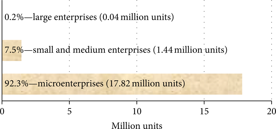
Structure of enterprise units in the European Union [3].

Structure of employees in the European Union [3].

Potential of European microenterprises [3].
These are very important characteristics that describe a distinct ability for dynamic growth production and the possibility of effective evaluation of microcompany instruments basically “over a night.” It can be said that microcompanies now make up a significant part of the enterprise subjects.
The specifications of enterprise unit structure implies diametrically different demands on information systems from the view of micro- and small sized companies in comparison with medium and large sized companies on the other hand [4]. They are
simple implementation,
possibility of modular concept for covering all necessary areas,
reliable and secure data formats and structures,
possibility of flexible data sharing with IS of the purchaser and supplier,
possibility of a trouble-free extension to the needed modules,
securing the possibility of a relatively fast transfer to IS higher levels when necessary, and
reasonable price (last but not least).
Various demands of companies have necessitated the next requirements for system [5]:
It has to enable the user to plan the production process from several viewing angles.
It cannot restrict new products put on the manufacturing process.
The enterprise subject should be limited when launching new products to the production process as little as possible.
It should be applicable for a wide range of businesses.
It should be modular.
Computer aided process planning (CAPP) is a very old idea. Niebel [6] presented the first idea of using the speed and consistency of computer to assist in the determination of process plans. In 1976 two CAPP systems (CAPP and MlPLAN) were developed [7]. Subsequently Wysk (1977) presented a generative system for detailed process selection titled APP AS [8]. Since then CAPP has begun to be widely addressed. Process planning is first defined by Chang and Wysk [9] as the function within the manufacturing facility that establishes which processes and parameters are to be used to convert a workpiece to a finished part from its initial form to the fina1 one predetermined in an engineering drawing. Process planning is that part of manufacturing engineering which covers the translation of engineering design into the most efficient method of manufacturing [10].
Because of the wide range of relevant scientific research in areas that include computer aided design process planning in the past two decades, it is very difficult to encompass all of it. Alting and Zhang [11], Vuković et al. [12] and Kiritsis [13] provide detailed reviews of the scientific research of CAPP. Although [11, 12] give an overview of research older than two decades, they cover the area of setting up grounds for the CAPP system and an overview of these works can give a good idea of the basic preconditions for setting up such systems. Marri et al. [14] give an overview of research of the CAPP system based knowledge and also classify approaches for CAD-CAPP-CAM feature recognition. Eversheim and Schneewind [15] and ElMaraghy et al. [16], based on the review of scientific research of CAPP, provide guidelines for future research. Park [17] considered that a knowledge base should be not merely a set of rules, but a framework of process planning that can be controlled and customized using rules, and proposed a knowledge capturing methodology, in which four knowledge elements, facts, constraints, the way of thinking and rules for process planning, were derived from the model of process planning that was represented by a traditional three-phase modelling framework consisting of object model, functional model and dynamic model (decision logic and decision variables). Ramana and Rao [18] summarized the previous work and key issues related to data and knowledge modelling for product design and process planning.
In the history of computer aided process planning two different ways of obtaining the process plan can be observed [19, 20]:
variant process planning,
generative process planning.
Further development of the generative approach goes in the direction of dynamic generation of process plans, while the variant approach adopts some properties of the generative approach. The variant approach uses the principles of the group technology concept and plans are generated using elaborated, generic plans for a family of products. The generic process plan is taken from the database and with minimal changes is adapted to a specific case [21, 22]. Generally, process planning systems are oriented to one of this way. But each technique it features with some advantages. Exploitation benefices of one of both can be obtaining by help combination of them [23]. Though numerous studies have been reported, they are limited to academic discussion and prototype demonstration in principle, and it is not easy to find a commercial CAPP system applicable to complicated objects [24].
Today a great number of Eastern European companies have different process planners who make different process plans for the same parts, resulting in inconsistencies and extra paper work and they are applied in heterogeneous data environment. Computer aided process planning (CAPP) systems can help in overcoming these inconsistencies. CAPP aids the creation of process plans and increases the flexibility of manufacturing. Process planning is a task which requires a significant amount of both time and experience. Computer support or computerised process planning systems can help reduce process planning time and increase plan consistency and efficiency. The requirement to find such an information system, which could be adapted to Eastern Europe market conditions, brings the idea to create a new system at FMT TU Košice with a seat in Prešov.
Based on the facts listed above, the system was built to be able to combine the following technological approaches:
individual technology,
type technology, and
group technology.
3. Theory of Multiple Access Process Planning
The base theory of multiple access process planning (MAPP) software application considers the production process (not only during its project phase, but also during production) as a homogenous unit, including technological and labour processes organised via various possible parallel phases. The final product can then be processed in an optimized way according to the set conditions whilst also fulfilling the demands required by the consumer. On the basis of this theory it is possible to create a combination of possibilities of various techniques used in individual process plans. This strategy is aimed at achieving the specific goal of the production unit. The main objectives of this theory are
creation of the unified definition environment for all the factors immediately influencing the result of production process and
a flexible interface which enables bidirectional exchange of the required information with all surrounding systems.
Via a unified definition environment the philosophical and conceptual unity is secured within the whole issue falling into the area of multiple access process planning, a distinct classification product constituent and the production laws of the sequence of operation projection allow the use of several possibilities designed by the information system.
The flexible interface of the system has to enable effective work in the production environment in a way that all the individual and relevant systems (CAD/CAM applications, wage records, accounting, material management, …) are interconnected and secured via suitable interfaces. This is done in order to prevent errors caused by data redundancy, human error, but also to reduce response time to a minimum [1, 2]. Greatly tested Multiple Access Process Planning (MAPP) system works with a wide variety of CAD/CAM systems or their modules (models, CL data & NC programs, etc.) and uses various methods of technological approaches such as multiple access process plan design corresponding to the requests of European plants.
3.1. Mathematical Structure of MAPP System
The objects in machine engineering (as are e.g., the parts, machines, equipment, and other) are possible to model during various stages with various goals. These objects can be regarded as various types of models (physical, simulation, computer, mathematical and other). Every one of these objects can be considered as system, which consists of next features or, on the other hand, as the feature that is part of a system [25].
If the object property is possible to express by means of a basic unit or it is multiple, it can be spoken as a numeric property. The basis of numeric formulation of numerical properties is an agreement by means of which we determine the basic unit.
Some properties are not possible to express in the way listed above, so nonnumerical properties are applied. On the other hand, according to a special agreement, nonnumerical properties can be formulated by numbers, too, namely by a numeric code. Apart from the numeric code alphabetical or alphabetic-numeric codes can be used. In machine engineering both—numerical expressions (e.g., at the part dimensioning, where conventional unit is in millimetres) and nonnumerical expression (e.g., at the coding of part in group technology) can be found [26, 27].
The smallest unit of system model is considered a feature that is indicated by a small cursive letter (with or without index), for example, a1, a2, aj, …, an. Features with the same characteristics can be grouped into a set.
A set is defined, when all its features are decided whether they have a specific property that belongs to a set. The sets are indicated by capital letters A1, A2, …, A i , …, A n . There are relations between sets. Some of them are shown in Table 1.
In regard to a large number of parameters that are variable in consequence of the varied manufacturing process conditions, it is more suitable to use a type of code which is reserved for the characteristic properties of object at their starting positions. Other positions are attached to an attributed code according to the need to define the classification of the object. On the basis of this structure it is possible for the manufacturing system to be considered a set, which is a unification of subsets marked as subsystems.
Newly designed system can be expressed by the relation (Figure 5):

where MS is the manufacturing system, E is the equipment, S is the segment, and O is the operation.

Mathematical model of manufacturing system.
3.1.1. The Subsystem Equipment
The term “equipment” in this case is used to cover a wide spectrum of product equipments, such as
production space (the halls, workshops, …),
equipment for energy production and energy distribution,
machining equipment,
tools,
jigs and fixtures,
machines,
machining equipment,
equipment for workshops of manual operations,
equipment of assembly plants,
measuring and testing equipment,
conveying devices,
equipment for storage, and
other devices (e.g., computer techniques, …).
Machining equipment can be divided into the following:
(a) Machines. These machines are possible to divide into various aspects; the most advantageous is the classification on the basis of technology in use. In this case we can speak, for example, about the machines for
machining
turning,
milling,
drilling and boring,
machining centres,
other,
moulding,
casting,
welding,
assembling,
and other.
(b) Tools. Tools are a very important part of the production process. For exact coding it is necessary to regard
the technological operation that the tools are able to execute,
the technological and geometrical limitation,
the maximal and minimal values of the working parameters, and
the type of the work holding.
(c) Jigs and Fixtures. It is needed to determinate the coding of jigs and fixtures
devices, which they can be used on,
maximal and minimal values of the working parameters, and
the environment in which jigs and fixtures can be used.
(d) Accessory Equipment. The accessory equipment is often essential and necessary for the flow of some operations. It was possible to choose the hybrid type of code in regard to the ambiguity of its using definition (e.g., the same medium can be used as the cooling mixture and at other times as oil).
The set Equipment can be mathematically expressed as follows:

E is the equipment, MS is the manufacturing space (halls, workshops, …), EP is the equipment for power production and distribution, ME is the manufacturing equipment, MTE is the measuring and testing equipment, TE is the transport equipment, SE is the storage equipment, and OE is the other equipments (e.g., computer techniques, …).
All of these sets are a union of subsets. For example, the set ME can be written down as

M is the machines, T is the tools, F is the fixtures, AME is the auxiliary manufacturing equipment, EMO is the equipment for manual operation, and AE is the assembly equipment.
The set machines can be divided into the next structuring according to the type technology as follows:

M is the all plant machines, MM is the machining machines, CM is the casting machines, WM is the welding machines, AM is the assembly machines, MoM is the moulding machines.
In the relation to the machining machines

MM is the machining machines, MO1 is the turning machines, MO2 is the milling machines, MO3 is the drilling and boring machines, MO4 is the machining centre, and MO5 is the grinding machines.
Production plant disposes a certain number of turning machines that are featured in the set MO1:

or

mi is the is ith machining machine and n is the whole number of machining machines in the plant.
Individual turning machines are characterized by properties, which define the machine's selection for the turning of a concrete part. For example: for the machining of too long shafts are suitable centre lathes and so forth. The relationship between turning machines and its properties can be written down by functional dependency as follows:

MO1 is the the set of all plant turning machines, pi is the ith property of turning machine, p1 is the lathe type, p2 is the control system, p3 is the tool equipment, p4 is the dimensions, p5 is the energy and precision, p6 is the turret head type, p7 is the speeds, p8 is the feeds, and p9 is the postprocessors.
If the examined object has more than one substantial property from the view of solved task goals, then the featured set that contains lathes suitable for turning operation according to selected property can be obtained by partial derivation. Consider

simultaneously with

where M1O1 is set of lathes, which satisfy the request for machine selection according to a specific property.
For example:

where M1O1 is set of turning turning plant machines that are suitable for machining very long parts.
Similarly other sets M j O1 that originate by differentiation MO1 with respect to jth property can be obtained. Consider

and simultaneously every M j O1 holds

Every one of these subsets M j O1 include various features, such that individual requests vj of different turning machines are satisfied.
Lathes that conform to all requests can be found as intersection of sets

MoptO1 is a set of turning machines that conform to the requests of all selected properties.
The following 3 cases can occur.
MoptO1 is one-featured set, which means: if all conditions are fulfilled, a concrete part is possible to turn on one suitable machine only.
Set MoptO1 has several features, which means that it is necessary to choose other criteria for machine selection (e.g., it is necessary to find out, which of the machines is free for the machining at this time).
Set MoptO1 is empty. In this case one of the machine choices is needed to be left out according to some of the properties (the majority of the time it is the property that influences the selection process the least) or the situation has to be solved in another manner (e.g., by producing a selected part in an alternative plant or by buying a new machine with needed parameters which on the other hand increases production costs).
The principle of this simplified model is applicable not only to lathes or other machines but also to the next subsets of Equipment subsystem also even for subsystems Segment and Operation.
3.1.2. The Subsystem Segment
The basis of subsystem “segment” is the classification code for the segment description, which represents the starting point of whole system. The suggested coding system keeps space for the process plans, creating not only a cutting technology but also other technologies [28].
The codes cover the following characteristics [28]:
the geometrical shape,
the class of the part,
the manufacturing characteristics, and
the class of dimensions.
During the creation of the software application, several manners of the segment classification were suggested, according, for example, to the types of surfaces that did not comply with the view of the classification complexity.
The coding of the segment in a new software application came from the assumption that the data registered in this module used in the creation of technological or drawing documentation and the parameters that had already been defined would be possible to record in another database module. Code (Figure 6) can appear very difficult at the first sight, but its creation is very simply to workout in user interface and it is aided by already partially charged data bank. New code is formed by 8 parts. The final version of the designed code and its structure are shown in Figure 6. The basic characteristics of individual code segments shown in Figure 6 are explained in Table 2.
Structure of individual code parts in subsystem Segment.


The structure of individual code parts in subsystem Segment.
In this code, for example, the 4th part of code describes the raw product. The code for the raw product size is created by 4 characters. The first position is defined by an alphabet letter, which determines the kind of raw product (e.g., the sheets, steel strips, … fall into group “A”). The second, third and fourth characters give the standard sequence for a specific type of raw product in the database module. For the industrial plant it is possible to register up to 1000 standards for one type of raw product.
An example of the selected surface coding system with the possibility to manufacture surfaces by individual technological operations is shown in Table 3. Characters 0 or 1 describe the possibility of manufacturability.
An example of surface coding with the possibility of manufacturability by individual technological operations.

3.1.3. Subsystem Structure of Operation
It is possible to specify the concrete machining operation by means of three stages [29]:
the class of the machining,
the type of the machining, and
the process of the machining.
An example of the Structure of operation coding is shown in Figure 7, which displays the code meaning.

An example of the structure of operation coding.
Inside the created software application other technologies also exist and so this subsystem was expanded to the stages:
technology,
technological class,
technological type, and
technological process.
3.2. Database Design
Computer aided process planning (CAPP) represents activities leading up to the creation of production documentation and the details of material equipment for the production process.
The cost structure analysis of small and medium series production indicates a significant amount of CAPP in the production costs composition. From the point of view of these analyses it is very important to pay considerable attention to the CAPP area which can, as a result, influence the output costs of a product and its quality in great measure [30, 31].
When designing a new product the aim is to secure or increase its technical value not only by systematization of the production process but also by increasing the level of the supporting tools. These tools are used for the rational processing of production documentation and data needed for planning [32].
The production system design can be logically divided into parts as follows:
product design
design procedures
design methods
value analysis
manufacturing design
technological structure planning
process planning
NC programming
studies of labour and production costs
work analyses
work measurement
wage schemes.
According to the analysis of requirements of real plants concerned in the project, necessary data structures by means of relation database were prepared at University. A small fraction of database tables used and their relations are shown in Figure 8.

Database tables and relations, fraction of used structure.
The following steps were created by the means of following the database system tools:
user rules for problem definition,
queries for selecting required data,
forms for data editing by operators,
reports for exploring relevant data, and
procedures for operating with data.
For sufficient database working the filling of all relevant information into the interface for storing properties and characteristics of production segment is required. Under the term “segment” the purpose of this information system is meant for all manufacturing objects from part, through to subassembly and assembly groups on to final product. This interface is asked for basic information about the production segment and next indications (numbering followed in Figure 9). They are
identification of segments by basic information,
raw product identification,
information about prescribed tolerances,
heat treatment information,
surface treatment information,
surface roughness information,
documents (definitions and full electronic form) related to the segment of production,
surface generating volume of the production segment,
indications for individual technology,
indications for type technology,
indications for group technology, and
indications for case cancelling of the production segment.

Interface for definition of properties and characteristics of the production segment (part, subassembly, …, final product). 1: Identifications of segment, 2: raw product identification, 3: tolerances, 4: heat treatment information, 5: surface treatment information, 6: surface roughness information, 7: document definitions, 8: segment surfaces generating volume, 9: individual technology, 10: type technology, 11: group technology, 12: cancelling of production segment.
All the procedures have to be worked out by operators with the knowledge of advantages and disadvantage of every strategy, which can be used in the process of a production segment. To frame this phase it is possible to prepare the classification of this segment for future handling as well as possible manufacturer conditions.
Classification is realized according to the rules of group technology, where first a group representative is selected, or created, and next step consists of the classification of a processed component and it is categorisation into a group according to the selected criteria [29].
After inputting all the needed information—production segment data and classification—the information system is ready for definition according to manufacturing characteristics (Figure 10). It is suitable to create more process plans (no. 6) appropriate for the actual production segment (no. 5). For example, for every hypothetic event, which is able to occur in the future, the operator creates one process plan with the equivalent strategy. In the case of a new unpredictable state a new strategy can be generated. Basic versions of prepared process plans can be created for these cases:
maximum efficiency,
minimal cost and
change of goods flow (in the occurrence of use of all machine tools).

Interface for definition of manufacturing characteristics.
There is possibility to define more phases inside every process plan (no. 7). Every phase has a relatively independent set of operations. For example, the first phase may be casting, the second-machining and the final-surface treatment. The operator can prepare the manufacturing sequence in the following way:
the handle writing of technological operation cycles (no. 1),
NC program (no. 2)—direct writing by operator or established for group in frame of GT or downloaded from NC program creator,
sequence of operation pictograms (no. 3), and
simulation sequence (video, animation, …) (no. 4).
3.3. NC Program Creation inside MAPP Conditions
The introduction of the PC into the process plans creation predicts the existence of
information on the type of part that determines the method of working (e.g., tooling, milling, grinding, …) and
information flow that represents the processing of all the information needed for the manufacturing of operation control.
Both these facts are found through the application of NC machines in flexible conditions and of the automation of NC programs and corrections. This application needs to flexible from the view of operators request and the environment of the MAPP created so that operator is able to work in the following ways:
hand programming by direct writing of the NC program
is suitable for very simple operations
typical example is turning (the tool moving only on two axes)
partially automated programming by direct selecting of the commands from the MAPP environment
the use of group technology for the simple parts mainly at turning with possibility of the application to other types of machining, for example, milling.
Automatic generation of NC program in CAD/CAM system conditions
NC program is saved in a native format of control system in a selected manufacturing machine through MAPP software application,
NC program, in the relation to the part (all commands for NC processing are in one file) or it is in relation to the group of operations that results in a specifically shaped feature (e.g., no cylindrical hole).
This type of NC program generation is suitable for complex shaped parts, where an NC program can consist of several thousands of rows. The generation is done on the basis of geometric data of the part (assembly, subassembly), tool, jigs, and so forth. It depends on the choices of technology and execution strategy.
An example of the possibility of creating a partially automated NC program, with the utilization of group technology inside MAPP application, can be shown by a group representative for shaft parts. (Figure 11) It is represented by a 3D model with plenty of shaped and geometrical features (cylindered surfaces, conical surfaces, threaded surfaces, concave surfaces, convex surfaces, chamfers, rounds, holes, round, chamfer, pin lock groove, slot, …).
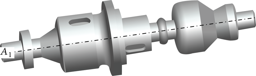
Complex-group representative.
On the basis of this component, Pro/Engineer as one of big CAD/CAM systems allows to create other similar parts within group technology. It is realized in the Family table module by the feature skip variation through commands Yes/No or by dimensional change. The environment for new part definition on the basis of already existing information is shown in Figure 12.

Preparation of new components within group technology.
Some parts generated by means of the Family table following one group representative are shown in Figure 13. The parts from no. (1) till (9) in this figure originate by varying some of the features (surfaces with certain shape, lock grooves, slots, chamfers, rounds, etc.) which these parts have or not.

The parts generated on the basis of group representative.
3.4. MAPP Verification
The verification of MAPP in relationship to object manufacturing was based on two approaches to technological documentation preparation:
the group representative and contextual parts and
the parts undefined to a set inside the group technology.
These process plans and NC programs were done in the module Process plan creation for every type.
Consequently these outputs were generated through Print sets:
process plan,
NC program for a derived part, and
production time summary.
The data verification was realized on the part displayed in Figure 14. It was prepared on the basis of group representative shown in Figure 11 by means of the Family table in CAD/CAM system Pro/Engineer.

3D model of parts for NC program verification.
The model shown above was assigned inside the database to a group representative and its characteristics were loaded into MAPP within the interface shown in the Figure 15.

The object assignment to a group representative.
The CL data in CAM system was generated by means of a postprocessor transformed to a NC program for the selected control system.
On the basis of the aforementioned theory's characteristics, an information system was created and applied in real production conditions with computer aided process planning.
From the very beginning of the project, the established IS was suitable for analysis of real individual database objects (components, substructures, structures, finished product), that is, new analytical tools were created when required. Established solution served the purpose of easier and faster assignment of process parameters, the shortening of computer aided process planning and documentation time in real production conditions, as well as also supporting effective utilization of plant production based on a mathematical model at which object variation of computer aided process planning fulfills the required characteristics within the given production conditions. The output system data can be used to process the details of warehouse, economic and wage records for their control and optimization.
The final product “Launcher RM70”, for which the production database was verified, consisted of approximately 6 000 components as a result of the co-operation between a German company (providing investments and co-operation of the activities) and Slovak companies providing the technical process planning and the production of a final product. Real and virtual variations of vehicle “Launcher RM70” are shown in Figure 16.
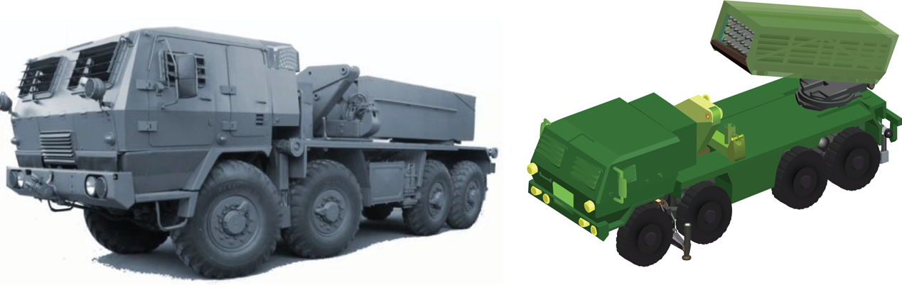
Real and virtual variations of the product “Launcher RM70.”
4. Conclusion
The main contribution of assigning the information system was elaborated on the basis of the multiple access process planning in real manufacturing conditions and can be summarized as follows:
reduction of the variability of warehouse stock (at first application by nearly 30%),
immediate information on product elaboration,
fast acquisition of the details via interfaces for the wage records and accounting,
flexible analytical tools enabling the adoption of better decisions, and
the acquisition of statistical values of the parameters applicable to plan production in the future.
The software application was created in a way to be easily implemented into an already existing information company structure via flexibly adjustable interfaces. It is also user-friendly, developed with the characteristics of GUI, typical for OS MS Windows, so that the basic grasp of its functioning does not require expensive training. Of course, if the maintenance of this system is to be productive, it has to be familiar to the given philosophy and possibilities of tactic and strategy planning, through which the production can be optimized.
The presented manufacturing information system is unique in possible cooperation with CAD/CAM system (practically with any known) and connectivity to other systems (accounting, stock, wages, etc.). This concept brings advantages mainly for microcompanies:
modular conception,
flexible interconnections to partners,
possibility of cooperation with wide variety of external software, and
convenient price.
All the particular know-how of using the described system shows new future tasks for research in these areas:
investigate a system for comparing 3D data for finding object similarity,
finding better interfaces for CL data creation, NC program sharing, alerts about 3D model changing, and so forth,
seeking certain data formats for communications between cooperating plants,
research for the general format of process plan data, and
investigation of production environments in other European countries.
Footnotes
Nomenclature
Conflict of Interests
The authors declare that there is no conflict of interests regarding the publication of this paper.
Acknowledgment
This paper originates with the direct support of Ministry of Education of Slovak republic by Grants KEGA 013TUKE-4/2014 and VEGA 1/0614/15.