
Abstract
A finite element approach is proposed for the acoustic analysis of automotive silencers including a perforated duct with uniform axial mean flow and an outer chamber with heterogeneous absorbent material. This material can be characterized by means of its equivalent acoustic properties, considered coordinate-dependent via the introduction of a heterogeneous bulk density, and the corresponding material airflow resistivity variations. An approach has been implemented to solve the pressure wave equation for a nonmoving heterogeneous medium, associated with the problem of sound propagation in the outer chamber. On the other hand, the governing equation in the central duct has been solved in terms of the acoustic velocity potential considering the presence of a moving medium. The coupling between both regions and the corresponding acoustic fields has been carried out by means of a perforated duct and its acoustic impedance, adapted here to include absorbent material heterogeneities and mean flow effects simultaneously. It has been found that bulk density heterogeneities have a considerable influence on the silencer transmission loss.
1. Introduction
The acoustic behaviour of dissipative silencers strongly depends on the properties of the absorbent material. In many modelling applications, it is necessary to predict accurately the acoustic performance in a wide frequency range. From a practical and computational point of view, it is easier for the silencer designer to consider homogeneous materials. Nevertheless, this assumption is often far away from reality, where material properties can present relevant spatial variations. Therefore, it can be important to take material heterogeneities into account when modelling bulk reacting fibrous materials as these variations are expected to significantly affect the acoustic performance of the silencer [1–4]. Material heterogeneities can be caused by an uneven filling of the chamber, for example, when the fibre is rolled around the central duct or it is pushed in the chamber. Selamet et al. [1] studied a dissipative silencer containing two concentric annular layers of absorbent material with different airflow resistivities in the absence of mean flow. In this work, a 2D analytical approach was used to compute the wavenumbers and transversal pressure modes in the central airway and the chamber. Finally, the transmission loss was obtained through the application of the mode matching technique considering the continuity conditions of the acoustic pressure and axial velocity at the geometrical discontinuities. A good agreement was found between the results derived from this method and FE calculations. In a later work of the same authors [2], the acoustic effect of voids inside the silencer, modelled by means of axially staggering filled/empty segments in the outer chamber, was studied considering a similar approach as the previous reference. In this case, the method provided good correlation with both experimental measurements and FE calculations. Antebas et al. [3, 4] presented a pressure-based FE approach to compute the transmission loss of perforated dissipative silencers including a continuously varying bulk density distribution. In these investigations, a linear function was proposed to model the axial variation of the bulk density, leading to heterogeneous material properties such as the flow resistivity, equivalent complex density, and speed of sound. Some numerical issues were found at very low frequencies in the presence of a moving propagation medium [3].
On the other side, anisotropy is likely to appear for silencers manufactured in such a way that the fibres are aligned in a specific direction or when a strongly directional mean flow exists within the absorbent material. Peat and Rathi [5] presented a FE approach to model the acoustic behaviour of dissipative silencers with anisotropic and heterogeneous properties caused by an induced flow, even if the material is initially isotropic and homogeneous. Despite being usual to place a perforated surface to protect the fibre and reduce the static pressure losses, a perforated duct was not considered in this study.
Heterogeneities can be also caused by the soot particles contained in the exhaust gases from the engine [6]. From a modelling point of view, this can lead to a variable material resistivity and therefore to a coordinate-dependent equivalent density and speed of sound [3, 4, 7]. The presence of a perforated screen [8, 9] has an impact on the silencer performance, and the fibrous backing material has a large effect on the acoustic impedance of the perforations [10, 11]. Therefore, material heterogeneities are expected to produce perforated duct impedance nonhomogeneities. Sullivan and Crocker studied the acoustic behaviour of a perforated surface in the absence of absorbent material [9]. Kirby and Cummings [10] presented empirical formulae for the acoustic impedance of a perforated surface with absorbent material located closely to one side of the plate in the presence of mean flow [10]. More relevant information describing the influence of the fibrous material on the acoustic performance of a perforated surface can be found in the work of Lee et al. [11].
The aim of the current work is to assess the influence of a continuously varying bulk density distribution on the acoustic performance of a dissipative silencer in the presence of mean flow. An approach based on the finite element method is presented, combining a velocity potential-based formulation in the central pipe with a pressure-based wave equation in the outer dissipative chamber [12]. This hybrid approach overcomes some numerical issues [3] of the pressure formulation at very low frequencies. Due to the low Mach numbers usually found in exhaust systems [13], flow noise [14] is not taken into account, while mean flow convective effects on the sound propagation and perforated duct impedance are retained.
2. Governing Equations
2.1. Derivation of the Finite Element Equations
Figure 1 shows an outline of the perforated dissipative silencer under study, consisting of a central duct (Ω
a
) carrying mean flow with axial velocity Umf and an outer chamber (Ω
m
) containing nonhomogeneous absorbent material. The boundary surfaces of Ω
a
and Ω
m
are Γ
a
and Γ
m
, respectively, while Γ
i
and Γ
o
denote the inlet and outlet sections and Γ
p
represents the perforated duct surface. From an acoustic point of view, the central airway can be characterized by means of the air density ρ
a
and the speed of sound ca, and the perforated screen can be modelled considering its acoustic impedance

Dissipative silencer with uniform mean flow and heterogeneous material properties.
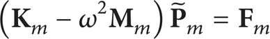
In the central airway Ω a carrying mean flow, a wave equation in terms of acoustic velocity potential is used [15],
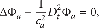
where Δ is the Laplacian operator and Φ
a
is the acoustic velocity potential, its gradient being the acoustic velocity
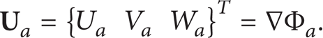
In addition, D t is the total time derivative, given by [15]

with

Assuming harmonic behaviour with angular frequency ω [13] and combining (1) and (3) yield

j being the imaginary unit.
In the outer chamber Ω m , the equivalent acoustic properties are coordinate-dependent, and therefore a suitable version of the wave equation is required to account for the heterogeneous properties of the absorbent material. The governing wave equation can be written in terms of acoustic pressure P m [3, 4, 12, 15] as follows:
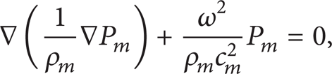
where both the equivalent complex density ρ m and speed of sound cm [7, 16] appear in the governing equation.
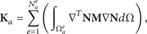
The finite element approach is now applied to (5) and (6). First, the air subdomain Ω a is considered, which yields [17]

where

If a similar procedure is applied to (6) associated with the absorbent material subdomain Ω m , the following expression is obtained:

where
Equations (7) and (9) are now combined to obtain the final system of equations. First, to achieve a more compact formulation, (7) can be written as

where the corresponding matrices and load vector are


The integral over Γ a that appears in (14) is taken only over the inlet/outlet sections Γi/o = Γ i ∪Γ o and the perforated duct Γ p , as the rigid wall condition is assumed for the remaining surfaces. For the transmission loss (TL) computations presented in Section 3, an acoustic velocity potential boundary condition is considered at the inlet, while an anechoic termination is supposed at the outlet section. These conditions are suitable for attenuation calculations, since TL is defined as the difference between the power incident on the muffler and that transmitted downstream into a tail pipe terminating anechoically [13].
Equation (9) is expressed as
and the FE matrices and load vector corresponding to the absorbent material subdomain are
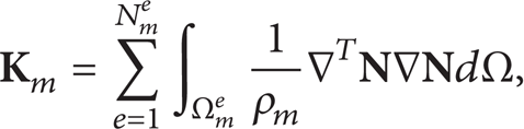

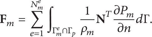
In this case, the integral over Γ m in (18) is taken on the perforated surface Γ p , as the chamber walls are considered rigid.
To combine (10) and (15), the acoustic coupling between the subdomains defining the silencer (Ω a and Ω m ) is done through the perforated duct. The integrals carried out over the perforated boundary Γ p in (14) and (18) are computed taking into account the definition of the acoustic impedance [13],

where U n is the normal acoustic velocity. Note that in the central duct the acoustic velocity potential Φ a is the field variable explicitly used for the FE computations, related to the acoustic pressure in the air P a through (4). According to the literature [10, 11, 18], the acoustic impedance depends on several parameters such as frequency, thickness, hole diameter, and porosity. In addition, a dependence exists on the absorbent material backing the perforations and the mean flow. Further details will be provided in Section 2.3.
Assuming continuity of the acoustic velocity through the perforations [19], the aforementioned load vector

The previous equation in compact form is

where the matrices have been defined as follows:

Finally, the load vector

the compact notation being

where the matrices are

By combining (10), (15), (21), and (24) the final system of equations is obtained:

where
2.2. Acoustic Model of the Material Heterogeneity due to Density Variations
An absorbent material can be characterized by equivalent acoustic properties, such as the wavenumber k m = ω/c m and the characteristic impedance Z m = ρ m cm; both of them are complex and frequency-dependent values [7, 16]. These properties are usually uniform in the literature due to the assumed homogeneity of the steady airflow resistivity R [20–22]. This fact means that also the bulk density of the absorbent material has to be constant, since its relationship with the material resistivity is given by the following expression [23]:
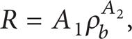
where the coefficients A1 and A2 can be obtained from a curve fitting process following experimental data. E glass fibre is considered in the calculations, whose coefficients are A1 = 5.774 and A2 = 1.792, thus providing a resistivity R = 30716 rayl/m for ρ b = 120 kg/m3 [23].
The bulk density is usually considered constant in the bibliography [11, 16, 18–25]. Heterogeneities can appear, however, due to the silencer manufacturing process, leading to spatial variations of the bulk density and material resistivity [1–4]. These are included in the current investigation by assuming that the extension of (27) produces good predictions; that is,

The numerical test cases considered in the calculations hereafter are axisymmetric for computation purposes (see Figure 2). The influence of the material heterogeneity on the acoustic performance is assessed as follows. The density is approximated by a bilinear function in the context of the current work, the dependence on the axial and the radial coordinates being ρ b (x,r) = c0 + c1x + c2r + c3xr. According to (28), the resistivity also depends on the coordinates and therefore the usual expressions of the characteristic impedance and the wavenumber [7, 16] have been modified here to include the presence of heterogeneities, giving

where Z a = ρ a c a is the characteristic impedance of the air and f is the frequency.

Axisymmetric perforated dissipative silencer under study.
2.3. Perforated Screen: Extension of the Acoustic Impedance Model
Kirby and Cummings [10] studied the acoustic impedance of a perforated pipe in the presence of an absorbent material and a relevant dependence was found. This was taken into account by including the material properties in the acoustic model associated with the perforations. The fibre considered in the current work is heterogeneous, so its acoustic properties vary from one point to another. Therefore, these spatial variations will modify the behaviour of the perforated screen and have to be included in its acoustic model to guarantee accurate predictions. In addition, the impedance of the perforations also depends on the mean flow, as shown in the works [13, 18, 26]. Here, an extension of aforementioned results is implemented, the perforated duct acoustic impedance being modified to include the heterogeneities produced by the bulk density variations [3, 4] together with the mean flow effects. The following expression is considered [3, 12]:

where it is worth noting (according to Figure 1) that the central perforated passage is parallel to the x-axis and it has uniform cross-section, x being the only relevant coordinate when computing the acoustic impedance of the surface. In addition, k a = ω/c a is the wavenumber, dh the hole diameter, σ the porosity, and F(σ) a factor that considers the acoustic interaction between the orifices of the perforated duct [27]. This factor is obtained here as the average value of the Ingard and Fok corrections:

Finally, ζ p (x) is the nondimensionalized perforated duct impedance considering the influence of the mean flow without absorbent material, which can be expressed as follows [26]:

The real and the imaginary parts of the previous expression are defined as

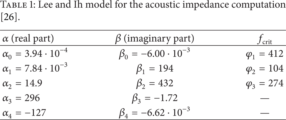
In (33), M = Umf/ca is the mean flow Mach number, tp is the perforated duct thickness, and fcrit is given by

The coefficients of expressions (33)–(34) for the computation of α, β, and fcrit were obtained by Lee and Ih [26] by the use of experimental data and a curve fitting procedure. The associated values are shown in Table 1.
Lee and Ih model for the acoustic impedance computation [26].
3. Results
The outline of the axisymmetric perforated dissipative silencer under study is shown in Figure 2. The dimensions defining the geometry are R1 = 0.0268 m, R2 = 0.05 m, L m = 0.3 m, and L i = L o = 0.1 m (both long enough to guarantee plane wave propagation in the inlet/outlet sections). The mesh considered to compute the silencer transmission loss consists of eight-noded quadrilateral elements whose approximate size is 0.01 m to obtain an accurate solution. The relevant characteristics of the perforated surface are σ = 0.2, (20%), t p = 0.001 m, and d h = 0.0035 m. E glass is considered in all the calculations.
As shown in the figure, the bulk density of the absorbent material is variable, being expressed by a bilinear function ρ b (x,r) that depends on the axial and the radial coordinates. For a particular numerical test case, the density distribution is defined from the “corner” density values ρb_ri, i = 1, 2, 3, 4, shown in Figure 2. In all the computations hereafter the bulk density law has been defined in SI units (kg/m3).
3.1. Validation
To validate the current approach, several computations have been carried out for different bulk density distributions in the absence of mean flow. Silencer transmission loss has been calculated for three uniform density configurations, whose values are ρ b = 100 kg/m3, 200 kg/m3, and 300 kg/m3, respectively, and for an axially varying distribution ρ b (x) = 366.67–666.67x (defined by ρb_r1 = ρb_r2 = 300 kg/m3 and ρb_r3 = ρb_r4 = 100 kg/m3) with an average value of 200 kg/m3. Each analysis has been computed twice for comparison purposes, by using the hybrid formulation (velocity potential/pressure) presented here and also a pressure approach, similar to that described in [4] in the absence of flow.
Figure 3 shows that the two sets of predictions (hybrid formulation and pressure approach) agree very well in the whole frequency region for the four density distributions. Increasing values of the bulk density produce higher material resistivities and deliver lower sound attenuation. The resistivity of E glass is relatively high and a blocking effect appears, reducing the penetration and dissipation of acoustic energy in the absorbent material. As expected, the transmission loss obtained with the variable density distribution lies between those obtained with uniform density computations corresponding to ρ b = 300 kg/m3 and ρ b = 100 kg/m3, since the latter are the upper and lower bounds of the variable density function, respectively. In addition, the comparison between the configurations with ρ b = 200 kg/m3 and ρ b (x) = 366.67–666.67x (both having the same average value) shows that transmission loss discrepancies can be significant if material heterogeneity is not considered. This is especially true in the mid-frequency range, where an examination of the TL curves provides differences over 4 dB (more than 10%). Hence, to avoid accuracy to be sacrificed, it is reasonable to employ the actual density distribution if possible rather than an average value.

TL (dB) of dissipative silencer with different bulk density distributions: blue solid line, uniform, ρ b = 100 kg/m3, hybrid; blue circles, same, pressure; red solid line, uniform, ρ b = 200 kg/m3, hybrid; red circles, same, pressure; black solid line, uniform, ρ b = 300 kg/m3, hybrid; black circles, same, pressure; magenta solid line, ρ b (x) = 366.67–666.67x kg/m3, hybrid; magenta circles, same, pressure.
3.2. Effect of Axially Varying Density on the Transmission Loss
Several computations have been carried out in this section to study the influence of axial density variations on the silencer performance. All the bulk density distributions used in the calculations are linear. The particular functions are given by ρb1(x) = 366.67–66.67x, ρb2(x) = 283.33–333.33x, and ρb3(x) = 366.67–666.67x (all expressed in SI units, kg/m3). Note that the same average density is considered in the three configurations, given by ρ b = 200 kg/m3, which is taken here as a reference. A value M = 0.2 has been assigned for the mean flow Mach number in all the finite element computations.
In Figure 4, a comparison between transmission loss predictions for the three bulk density distributions is made. An additional computation with uniform density ρ b = 200 kg/m3 is included. As can be observed in the figure, it is clear that increasing axial variations of the density distribution leads to higher attenuation mainly in the mid-frequency range, while only a slight acoustic impact is found at low frequencies, where density variations do not seem to have a relevant influence. A transition is found in the TL curves, since these tend to intersect at high frequencies (approximately 3200 Hz in Figure 4), where the previous trend seems to change; that is, lower attenuation is achieved as the density distribution has larger axial variation.
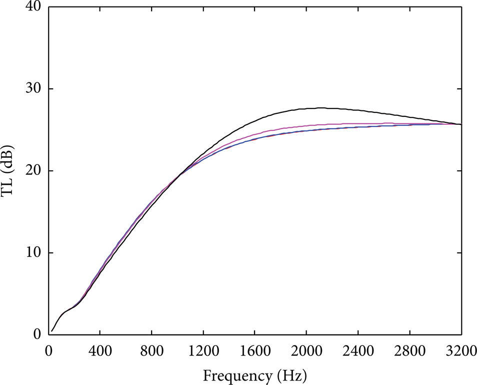
TL (dB) of dissipative silencer with different axially varying bulk density distributions (with the same average density of 200 kg/m3): red solid line, uniform, ρ b = 200 kg/m3; blue solid line, variable, ρb1(x); magenta solid line, variable, ρb2(x); black solid line, variable, ρb3(x).
3.3. Effect of a Radially Varying Density on the Acoustic Performance
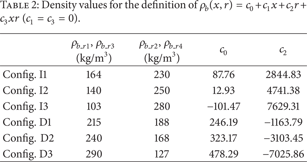
To assess the acoustic influence of radial bulk density variations on the silencer attenuation, two types of functions have been considered: (a) increasing density in the direction of increasing r and (b) decreasing bulk density as the radial coordinate increases. For both types, three different configurations have been evaluated. The corresponding values ρb_ri, i = 1,…, 4, for the computation of the density distribution are listed in Table 2. Common with the previous section, all the configurations yield an average bulk density ρ b = 200 kg/m3.
Density values for the definition of ρ b (x,r) = c0 + c1x + c2r + c3xr (c1 = c3 = 0).
The results associated with the configurations listed in Table 2 are depicted in Figure 5. A computation with uniform density ρ b = 200 kg/m3 is also included for comparison purposes. Again, a value M = 0.2 has been assigned for the mean flow Mach number in all the transmission loss calculations.
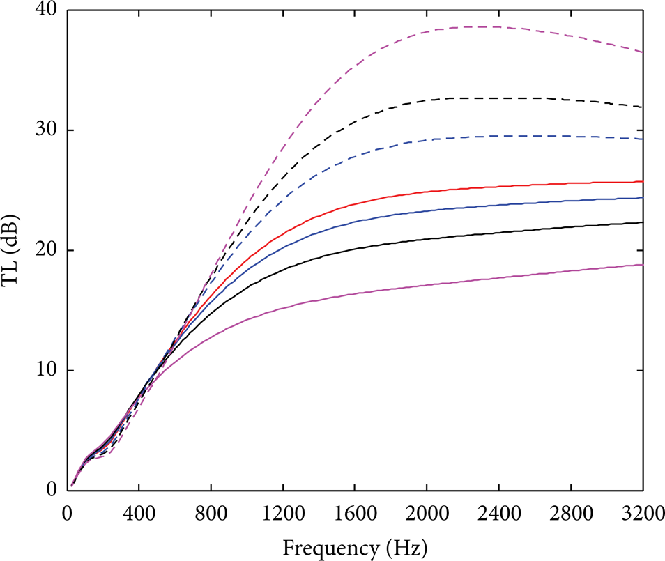
TL (dB) of dissipative silencer with different radially varying bulk density distributions (with the same average density of 200 kg/m3): red solid line, uniform, ρ b = 200 kg/m3; blue dashed line, config. I1; black dashed line, config. I2; magenta dashed line, config. I3; blue solid line, config. D1; black solid line, config. D2; magenta solid line, config. D3.
It is evident from Figure 5 that the acoustic impact of radial variations is stronger than this associated with cases with axially varying density (see Figure 4). The uniform density distribution sets a borderline between configurations I and D, showing that it is necessary to consider the radial density variations in the finite element computations to predict accurately the acoustic behaviour. While modelling the absorbent material as a uniform propagation medium allows computations to be made with some computational advantage, it yields a lack of accuracy in the transmission loss predictions. As can be observed, the discrepancies with radial variations are higher than those presented in the previous section for axially varying bulk density distributions.
Two different trends can be distinguished, depending on the type of bulk density distribution. Configuration I provides higher attenuations than D. In addition, the former exhibits higher transmission loss for larger density variations (except at very low frequencies), while the latter delivers higher attenuation curves as the radial variation decreases. A reasonable physical explanation of this behaviour is related to the fact that in configuration I the density increases with the radius, and hence the material resistivity is lower near the perforated surface. This allows a gradual absorption of the sound energy as the acoustic wave penetrates in the outer chamber, thus providing more attenuation than in configuration D, where the high material resistivity near the perforated surface makes the penetration of the acoustic wave within the chamber more difficult. This effect is relatively strong in Figure 5 due to the high resistivity presented by E glass. For example, a bulk density ρ b = 100 kg/m3 yields a resistivity R = 22155 rayl/m, while for a bulk density ρ b = 300 kg/m3 the resistivity is R = 158664 rayl/m. This means that increasing three times the material density yields a resistivity increase of approximately seven times. In principle, for less resistive materials, lower discrepancies are expected. Finally, regarding the low frequency range, transmission loss differences are not significant in Figure 5 below 500 Hz.
3.4. Influence of a Density Distribution with Axial and Radial Variations
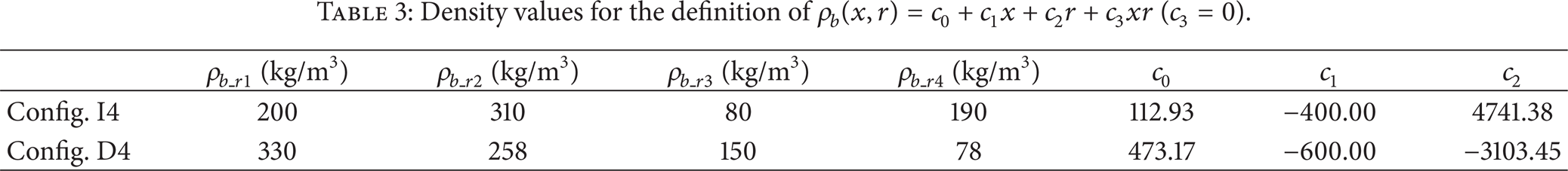
In this section, general density variations including axial and radial coordinate dependence are studied. The details are provided in Table 3, where two different configurations are described: (1) The density increases from R1 to R2 while an axial reduction takes place from the inlet to the outlet section (configuration I4); (2) The density decreases in both the axial and radial directions (configuration D4).
Density values for the definition of ρ b (x,r) = c0 + c1x + c2r + c3xr (c3 = 0).
For comparison purposes, configurations I2 and D2 (considering only radial variation), as well as the reference geometry with uniform bulk density, are also included in the analysis. In all the cases the value of the average density is 200 kg/m3 and the mean flow Mach number is given by M = 0.2. The corresponding transmission loss curves are shown in Figure 6, where it can be observed that the results are consistent with the previous FE computations. Configuration I4 provides higher attenuation than the uniform density case, similar to the radial examples of Figure 5, and it also delivers larger TL than configuration I2 since the latter does not include axial density variation (see Figure 4, where axially varying distributions are shown to increase the attenuation). In addition, configuration D4 provides lower sound attenuation compared to the uniform density case, which is consistent with the previous results of radially decreasing density distributions (see Figure 5), but it yields larger TL than configuration D2 since the latter does not include an axially varying distribution. To conclude, it is worth emphasizing that radial density variations have more influence on the attenuation than the axial ones. Therefore, when both are considered simultaneously with a similar magnitude in the FE model, the prediction of the silencer behaviour is mainly dictated by the radial density distribution.

TL (dB) of dissipative silencer with different radially and axially varying bulk density distributions (with the same average density of 200 kg/m3): red solid line, uniform, ρ b = 200 kg/m3; blue dashed line, config. I4; black dashed line, config. I2; blue solid line, config. D4; black solid line, config. D2.
Finally, the influence of the mean flow Mach number is considered next for the general density distributions I4 and D4. Figure 7 shows the transmission loss results obtained from the computations for M = 0, M = 0.1, and M = 0.2. In general, the attenuation is reduced as the mean flow increases, as expected. This is consistent with earlier studies with homogeneous material [19]. A change in trend is observed, however, for configuration I4 at high frequencies, with increasing Mach numbers yielding larger sound attenuation. When the mean flow increases, the cross point between the curves is shifted beyond the upper bound of the frequency range under analysis. For configuration D4 the previous comments are also valid, but the cross point seems to be beyond the frequency limits of the figure for all the curves. In this case, the influence of the mean flow on the acoustic performance is lower than in configuration I4.
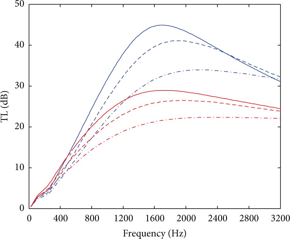
TL (dB) of dissipative silencer with radially and axially varying bulk density distributions (with the same average density of 200 kg/m3) and different mean flow Mach numbers: blue solid line, config. I4, M = 0; blue dashed line, config. I4, M = 0.1; blue dashed-dotted line, config. I4, M = 0.2; red solid line, config. D4, M = 0; red dashed line, config. D4, M = 0.1; red dashed-dotted line, config. D4, M = 0.2.
4. Concluding Remarks
A hybrid finite element approach combining an acoustic velocity potential formulation in the central airway with a pressure-based wave equation in the outer chamber has been presented to study the acoustic performance of perforated dissipative silencers with heterogeneous properties in the presence of mean flow. This represents an improvement over previously published models concerning automotive silencers. The material heterogeneities have been introduced by means of a nonuniform bulk density, thus providing a spatial-varying material airflow resistivity. This finally leads to coordinate-dependent equivalent acoustic properties such as the density and speed of sound, which are properly incorporated in the FE formulation developed in the current work. The coupling between the central perforated duct and the outer chamber has been carried out through a nonuniform acoustic impedance accounting for the material heterogeneity and the presence of mean flow.
In order to validate the approach presented here, several computations have been carried out in the absence of flow to compare the corresponding predictions with results calculated with a pressure-based wave equation, showing a good agreement. The influence of a number of bulk density distributions on the silencer performance has been then analysed in the presence of mean flow. It has been shown that the actual density distribution plays an important role in the FE acoustic predictions. Thus, it seems reasonable to employ it if possible, rather than an average value, to avoid accuracy to be sacrificed. The acoustic impact of radial density variations has been shown to be more relevant than the axial ones. In addition, as radial density increases higher transmission loss is obtained, while lower attenuation is achieved for decreasing bulk density in the radial direction. Finally, the mean flow has been found to reduce the silencer attenuation for the configurations under analysis.
Conflict of Interests
The authors declare that there is no conflict of interests regarding the publication of this paper.
Footnotes
Acknowledgments
This work was supported by Ministerio de Economía y Competitividad (Projects DPI2010-15412 and TRA2013-45596-C2-1-R), Conselleria d'Educació, Cultura i Esport (Project Prometeo/2012/023), and Programa de Apoyo a la Investigación y Desarrollo (PAID-05-12 and Project SP20120452) of Universitat Politècnica de València.